La page est en cours de chargement...

DS80IT26-001C LBT81043
FR
EN
I
T
IT500CLOUD
Interfaccia per App
My Elkron Family
Interface for
My Elkron Family App
Interface pour l’application
My Elkron Family
Manuale Utente
User Manual
Manuel de l'Utilisateur

2 IT500CLOUD
ITALIANO
DESCRIZIONE GENERALE
ATTENZIONE! In questo documento sono riportate le indicazioni essenziali sul prodotto in modo
da poter effettuare l’installazione, la configurazione ed eventuali aggiornamenti SW. Per ulteriori e
dettagliate informazioni fare riferimento al manuale installazione dell’App My Elkron Family
scaricabile dal sito www.elkron.com.
ATTENZIONE! L’interfaccia IT500CLOUD è compatibile solo con la centrale MP500/8 con
versione 1.10 o successive.
L’interfaccia IT500CLOUD è un dispositivo opzionale che permette di gestire da remoto tramite
dispositivi mobile e/o Tablet, la centrale MP500/8 attraverso un modem router dell’utente.
Il dispositivo può essere collegato alla rete LAN in due modalità:
WiFi
Ethernet (via cavo)
Accettarsi che, dalla rete domestica, sia possibile collegarsi ad Internet.
Dai dispositivi mobile e/o Tablet sarà possibile:
Attivare totalmente o parzialmente il sistema
Disattivare totalmente o parzialmente il sistema
Ricevere le notifiche degli eventuali allarmi
Verificare in tempo reale lo stato degli allarmi e relativi dettagli
Verificare in tempo reale lo stato di funzionamento del sistema
Leggere il contenuto dello storico della centrale
Escludere/Includere eventuali ingressi intrusione
Attivare/disattivare eventuali uscite programmate come comandabili
ATTENZIONE! Prima di procedere al montaggio, alla configurazione
ed alle prove funzionali, bisogna avere a disposizione un dispositivo
mobile (Smartphone o Tablet) dove installare l’App dedicata – My
Elkron Family, disponibile e scaricabile da Play Store o App store.
Per poter installare e utilizzare l’applicazione occorre disporre:
per dispositivi Android, versione 5.0 o superiore / per dispositivi IOS,
versione 10.0 o superiore.
Il modulo può essere installato in tre modi differenti:
All’interno della centrale MP500/8 in apposito alloggiamento (vedi Fig. 3)
Ad appoggio parete con viti e tasselli (vedi Fig. 2) utilizzando il contenitore ABS modello
CP/EP500
All’interno di una scatola ad incasso
Posizionare il dispositivo in un luogo:
Ad un’altezza non superiore a 2 mt dal piano di calpestio
Non soggetto a sbalzi eccessivi di temperatura
Protetto dall’impianto di intrusione
Lontano da forti campi elettromagnetici
Se si è scelto di collegare il dispositivo alla rete domestica tramite WiFi, verificare che ci sia
campo sufficiente.
Se si è scelto di collegare il dispositivo alla rete domestica via cavo (Ethernet):
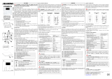
Nel caso di utilizzo del contenitore CP/EP500 con l’ausilio di apposito attrezzo, (vedi Fig. 2
punto 3) realizzare l’apertura sul coperchio per il passaggio del cavo ethernet (connettore)
Avere a disposizione quanto necessario per la connessione del cavo Ethernet ad apposito
connettore del dispositivo (vedi Legenda Fig. 1 - F)
Qualora non venga alloggiato nel contenitore CP/EP500, il tamper dovrà essere escluso
posizionando il DIP4 in posizione ON (vedi Legenda Fig. 1 - C).
My Elkron Family

IT500CLOUD 3
COLLEGAMENTO BUS
ATTENZIONE! Il collegamento e scollegamento dei dispositivi al bus deve essere sempre
effettuato a centrale non alimentata (rete e batteria sconnesse).
Fare riferimento al libretto d’installazione della centrale MP500/8 per quanto riguarda la sezione
dei cavi, le distanze e le estensioni.
I cavi impiegati devono rispondere alla norma IEC 60332-1-2 se di sezione 0,5 mm² o
superiore, oppure alla norma IEC 60332-2-2 se di sezione inferiore a 0,5 mm².
Collegare il dispositivo al BUS utilizzando i morsetti +, +D, D e ─ (Legenda Fig. 1 - E e Fig.3)
Il dispositivo può essere collegato al BUS in cascata, a stella o in modo misto.
La lunghezza complessiva di tutte le tratte del bus non deve superare i 400 metri.
CONFIGURAZIONE
Dopo aver posizionato e cablato il dispositivo al bus della centrale (operazione da fare a centrale
non alimentata) procedere con:
Acquisizione dispositivo sul bus
Per effettuare la procedura di acquisizione fare quanto segue:
1. Entrare in modalità di acquisizione da tastiera centrale MP500/8 digitando >Codice
tecnico>Manutenzione>OK.
2. Quando sul display compare la scritta “Acquisizione in corso”, premere il pulsante di
programmazione PROG (vedi Legenda Fig.1 - A),
3. Il buzzer della tastiera emette un suono e la scritta “Acquisizione in corso” scompare.
4. Il Led sulla scheda lampeggia velocemente tre volte, per indicare che l’indirizzo è stato acquisito.
5. Successivamente il Led inizia a lampeggiare in modalità da Access Point a funzionamento
normale.
Durante il funzionamento normale, premendo il pulsante di programmazione PROG (vedi
Legenda Fig.1 - A), la scheda esegue una breve sequenza-Led che specifica l'indirizzo acquisito.
La scheda interfaccia IT500CLOUD, in fase di acquisizione, viene riconosciuta dalla centrale
MP500/8 come Tastiera e gli viene assegnato il primo indirizzo disponibile. Prestare attenzione al
numero di tastiere già presenti nel sistema, in quanto il numero max consentito è di 8 (per
esempio se si acquisisce la scheda, dovranno essere presenti nel sistema al max 7 tastiere).
Configurazione parametri di rete del dispositivo
Il dispositivo è in grado di lavorare sia con rete Ethernet, sia con rete WiFi utilizzando la rete domestica
o una disponibile in modalità DHCP. Di fabbrica, il dispositivo si presenta in modalità “Access Point”,
sarà necessario definire la modalità di funzionamento attraverso l’APP “My Elkron Family”.
NOTA: Nel caso di utilizzo della connessione Ethernet, si può abilitare direttamente questa
modalità, seguendo le seguenti indicazioni:
Quando l'interfaccia è in funzionamento (2 lampeggi ogni 8 secondi) premere 5 volte il pulsante
“PROG”.
Dopo il comando attendere qualche secondo (circa 20 secondi), l’interfaccia si riavvia e si pone
nella modalità scelta (Ethernet).
Disalimentare l'interfaccia, attendere 10 secondi, e rialimentare l'interfaccia.
Per eseguire la configurazione procedere nel modo seguente:
Alimentare la centrale, se si è scelta la connessione alla rete domestica via cavo (Ethernet),
collegarlo al connettore presente sul dispositivo (vedi Legenda Fig. 1 - F).
Avviare l’applicazione My Elkron Family precedentemente installata e procedere come segue:
Premere il pulsante “Altro”
Selezionare menu “Aggiungi dispositivo”
Seguire le indicazioni che verranno date dal menu guidato
Se tutti i parametri sono stati programmati correttamente, il dispositivo è pronto per essere gestito
tramite l’App My Elkron Family.

4 IT500CLOUD
RESET DEL DISPOSITIVO
Nel caso in cui si volesse effettuare il reset del dispositivo occorre:
Da una qualsiasi tastiera presente nell’impianto, entrare con il codice Tecnico nel menu
“Manutenzione” e cancellare il dispositivo dal menu “Cancellazione/Tastiere” (il dispositivo in
precedenza è stato acquisito come tastiera, cancellare quella con l’indirizzo corretto. Per
ulteriori informazioni fare riferimento al Manuale Installazione della centrale MP500/xx.
Togliere l’alimentazione al dispositivo e rialimentarlo.
Tenere premuto per circa 10 secondi il pulsante di programmazione (PROG) fino a quando il
Led verde diventa fisso. A questo punto rilasciare il pulsante.
Il Led verde rimarrà fisso per qualche istante per poi lampeggiare un volta al secondo.
Il dispositivo ha effettuato il reset dei parametri.
A questo punto il dispositivo è pronto per essere nuovamente acquisito.
FUNZIONAMENTO LED
Stato
Segnalazione led
Reset hardware lampeggio per 10 secondi
Scheda resettata in modo Access Point, non
acquisita su centrale 1 lampeggio ogni circa 2 secondi
Scheda resettata in modo Access Point, acquisita 2 lampeggi lenti con intervallo di 8 secondi
tra una sequenza e l’altra.
Scheda collegata alla rete WiFi/LAN
a. acquisizione rete/indirizzo IP
b. rete acquisita, in ricerca Cloud Elkron/certificato
c. rete acquisita, Cloud/certificato acquisito
2 lampeggi lenti con intervallo di 1 sec tra
una sequenza e l’altra.
3 lampeggi lenti con intervallo di 1 sec tra
una sequenza e l’altra.
3 lampeggi lenti con intervallo di 8 sec tra
una sequenza e l’altra.
CARATTERISTICHE TECNICHE
Tensione nominale di alimentazione .............................................................................. 9 ÷ 15 V⎓
Assorbimento nominale ........................................................................... 70mA ±30% @ 13,8 V⎓
Banda di frequenza .......................................................................................... 2400 ÷ 2483,5 MHz
Potenza di uscita (Max) ..................................................................................................... 20 dBm
Baudrate connessione LAN ............................................................................................... 10Mbps
Baudrate connessione WiFi ............................................................................................... 54Mbps
Temperatura di funzionamento ................................................................................ -10°C ÷ +40°C
Umidità relativa media di funzionamento .......................................................................... 25 ÷ 75%
Dimensioni (l x h x p) ........................................................................................... 108 x 91 x 31mm
LEGENDA SIMBOLI
Simbolo
Spiegazione
Tensione di alimentazione continua
~ Tensione di alimentazione alternata
Fare riferimento al manuale di installazione del dispositivo

IT500CLOUD 5
ENGLISH
GENERAL DESCRIPTION
WARNING: This document contains important information on the product for installing, configuring
and updating the software. For more detailed information, see the My Elkron Family App
installation manual, which can be downloaded from the www.elkron.com website.
WARNING! The IT500CLOUD interface is only compatible with the MP500/8 control panel with
versione1.10 or later.
The IT500CLOUD interface is an optional device, which can be used to remotely manage the
MP500/8 control panel using a mobile device and/or tablet via a modem router.
The device can be connected to the LAN network in two ways:
WiFi
Ethernet (cable)
Make sure you can connect to the Internet through the home network.
From a mobile device and/or tablet you can:
Totally or partially arm the system.
Totally or partially disarm the system.
Receive notifications of any alarms.
Check the status of the alarms and their details in real time.
Check the status of operation of the system in real time.
Read the contents of the control panel history.
Exclude/Include any intrusion inputs.
Activate/Deactivate any outputs programmed as commandable.
WARNING! Before proceeding with installation, configuration and
functional tests, a mobile device (Smartphone or Tablet) must be available
to install the dedicated App - My Elkron Family, available and
downloadable from the Play Store or App store.
In order to install and use the application you must have:
for Android devices, version 5.0 or higher / for IOS devices, version 10.0 or
higher.
The module can be installed in three different ways:
Inside the MP500/8 control panel in a special location (see Fig. 3)
Wall-mounted with screws and plugs (see Fig. 2) using the ABS box model CP/EP500.
In a flush-mounting box
Place the device in a place:
At a height not exceeding 2 metres from the floor.
Not subject to excessive fluctuations in temperature.
Protected by the burglar alarm system.
Away from strong electromagnetic fields.
If you have chosen to connect the device to the home network via WiFi, check that there is
sufficient range.
If you have chosen to connect the device to the home network through a cable (Ethernet):
In the case of using the box CP/EP500 with the aid of a special tool, (see Fig. 2 point 3)
make an opening on the cover for the passage of the Ethernet cable (connector).
Prepare everything you need to connect the Ethernet cable to an appropriate connector of
the device (see Legend Fig. 1 - F)
If it is not located in the box CP/EP500, the tamper must be excluded by positioning the DIP4 in
the ON position (see Legend Fig. 1 - C).
My Elkron Family

6 IT500CLOUD
BUS CONNECTION
WARNING! Always connect and disconnect the devices to the bus with the control panel not
powered (mains and battery disconnected).
Refer to the installation manual of MP500/8 control panel with regard to the cable section,
distances and extensions.
Wires with cross-section area of 0.5 mm² or larger must comply with IEC 60332-1-2; wires
with cross-section area smaller than 0.5 mm² must comply with IEC 60332-2-2.
Connect the device to the BUS using terminals +, +D, D and ─ (Legend Fig. 1 - E and Fig.3)
The device can be connected to the BUS in cascade, star or mixed mode.
The total length of all bus stretches must not exceed 400 m.
CONFIGURATION
After having positioned and wired the device to the bus of the control unit (operation to be
performed with the control unit not powered) proceed with:
Device acquisition on the bus
Proceed as follows to perform the acquisition procedure:
1. Enter in the acquisition mode from keypad MP500/8 control panel, by typing > Code > Technical
>OK.
2. Press the programming button “PROG” when the message "Acquisition in progress" appears
on the display (see Legend Fig.1 - A),
3. The keypad buzzer sounds and the "Acquisition in progress" message disappears.
4. The LED on the board blink quickly three times to indicate that the address has been acquired.
5. Then, the LED starts blinking in Access Point mode with normal operation.
During normal operation, by pressing the programming button “PROG” (see Legend Fig.1 - A), the
board runs a short LED sequence, which specifies the address acquired.
The IT500CLOUD interface board being acquired, is recognised by the MP500/8 control
panel as a keypad and the first available address is assigned to it. Pay attention to the number of
keypads already present in the system. The maximum number allowed is 8 (e.g. if a board is
acquired there may be up to 7 keypads in the system).
Device network parameter configuration
The device can work both either with Ethernet network or with WiFi using your home network or
one available in DHCP mode. By default, the device is in "Access Point" mode, it will be
necessary to define the operating mode through the “My Elkron Family” App.
NOTE: If the Ethernet connection is used, this mode can be enabled directly, following the
instructions below:
When the interface is operating (two blink every 8 seconds) press the “PROG” button 5 times”.
After the command wait a few moments (about 20 seconds), the interface restarts and goes into
the chosen mode (Ethernet).
Power off the interface, wait 10 seconds, and power up the interface again.
Proceed as follows to configure:
Power the control unit, if you have chosen to connect it to your home network via cable (Ethernet),
connect it to the connector on the device (see legend Fig. 1 - F).
Start the My Elkron Family application previously installed and proceed as follows:
Press the “Other” button.
Select the "Add Device" menu.
Follow the instructions which will appear on the guided menu.
If all the parameters were programmed correctly, the device is ready to be managed via the My
Elkron Family App.

IT500CLOUD 7
RESET OF THE DEVICE
Proceed as follows to reset the device:
From any keypad in the system, enter the Installer code in the "Maintenance" menu and
delete the device from the "Delete/Keypads" menu (the device was previously acquired as a
keypad, delete the one with the correct address. For more information, refer to the
MP500/xx control panel installation manual.
Disconnect the power supply of the device and reconnect it.
Hold down the programming button (PROG) for at least 10 seconds until the green LED
lights up fixed. Now release the button.
The green LED will remain fixed for a few moments and then flash once a second.
The device has performed the reset parameters.
At this point the device is ready to be acquired again.
LED OPERATION
Stat
us
Led signaling
Hardware Reset blink for 10 seconds
Board reset in Access Point mode, not acquired
by control panel 1 blink approximately every 2 seconds
Board reset in Access Point mode, acquired 2 slow blinks with an interval of 8 seconds
between sequences
Board connected to WiFi/LAN
a. Network/IP address acquisition.
b. Acquired network, searching for Elkron
Cloud/certificate.
c. Network acquired, Cloud/certificate acquired
2 slow blinks with an interval of 1 seconds
between sequences.
3 slow blinks with an interval of 1 seconds
between sequences.
3 slow blinks with an interval of 8 seconds
between sequences.
TECHNICAL SPECIFICATIONS
Nominal power voltage .................................................................................................. 9 ÷ 15 V⎓
Rated Current ........................................................................................... 70mA ±30% @ 13,8 V⎓
Frequency band .............................................................................................. 2400 ÷ 2483,5 MHz
Output power (Max) ............................................................................................................ 20 dBm
LAN baud rate ................................................................................................................... 10Mbps
WiFi baud rate ................................................................................................................... 54Mbps
Operating temperature............................................................................................. -10°C ÷ +40°C
Average relative humidity during operation ...................................................................... 25 ÷ 75%
Dimensions (w x h x d) ........................................................................................ 108 x 91 x 31mm
KEY LEGEND
Symbol
Explanation
Direct current power voltage
~ Alternating input voltage
Refer to the device installation manual

8 IT500CLOUD
FRANÇAIS
DESCRIPTION GÉNÉRALE
ATTENTION ! Ce document contient les informations essentielles sur le produit afin qu’on puisse
effectuer l’installation, la configuration et les mises à jour logicielles éventuelles. Pour plus
d’informations, se reporter au manuel d’installation de l’application My Elkron Family,
téléchargeable à l’adresse www.elkron.com.
ATTENTION ! L'interface IT500CLOUD est uniquement compatible avec la centrale MP500/8
avec la version 1.10 ou ultérieure.
L’interface IT500CLOUD est un dispositif optionnel qui permet de gérer à distance via des
dispositifs mobiles et/ou des tablettes, la centrale MP500/8 par un modem routeur.
Le dispositif peut être connecté au réseau LAN de deux manières différentes :
WiFi
Ethernet (via câble)
S’assurer de pouvoir se connecter à Internet à partir du réseau domestique.
À partir des dispositifs mobiles et/ou des tablettes, il sera possible de:
Activer entièrement ou partiellement le système.
Désactiver entièrement ou partiellement le système.
Recevoir les notifications des alarmes éventuelles.
Vérifiez l'état des alarmes et leurs détails en temps réel.
Vérifier l’état de fonctionnement du système en temps réel.
Lisez le contenu de l'historique de la centrale.
Exclure/Inclure toutes les entrées d'intrusion.
Activer /Désactiver toutes les sorties programmées comme commandable.
ATTENTION ! Avant de procéder à l'installation, de configuration et de
fonctionnement, un dispositif mobile (Smartphone ou Tablette) doit être
disponible pour installer l'App dédiée - My Elkron Family, disponible et
téléchargeable depuis le Play Store ou l'App Store.
Pour installer et utiliser l'application, vous devez avoir:
pour les dispositifs Android, version 5.0 ou supérieure / pour les dispositifs
IOS, version 10.0 ou supérieure.
Le module peut être installé de trois manières différentes :
À l'intérieur de la centrale dans un logement spécial (voir Fig. 3)
Montage mural par des vis et des chevilles (voir Fig. 2) en utilisant le boîtier en ABS modèle
CP/EP500
A l’intérieur d’une boîte encastrée.
Placer le dispositif dans un endroit :
A une hauteur ne dépassant pas 2 mètres du sol.
Non exposé à des écarts de température excessifs.
Protégé par le système anti-intrusion.
Loin de champs électromagnétiques puissants.
Si on a choisi de connecter le dispositif au réseau domestique via WiFi, vérifier que le champ est
suffisant.
Si on a choisi de connecter le dispositif au réseau domestique via câble (Ethernet) :
A l’aide d’un outil spécial, dans le cas d'utilisation de la boite CP/EP500 (voir Fig. 2, point 3),
pratiquer une ouverture sur le couvercle pour le passage du câble Ethernet (connecteur).
Disposer du nécessaire pour connecter le câble Ethernet au connecteur du dispositif (voir
Légende Fig. 1 - F)
Si ce n'est pas logé dans la boîte CP/EP500, le tamper doit être exclu en portant le DIP4 en
position ON (voir Légende Fig. 1 - C).
My Elkron Family

IT500CLOUD 9
CONNEXION DE BUS
ATTENTION ! La connexion et la déconnexion des dispositifs au bus doivent être effectuées
lorsque la centrale est hors tension (réseau et batterie débranchées).
Pour la section des câbles, les distances et les rallonges, se reporter à la notice d’installation de la
MP500/8.
Les câbles utilisés doivent satisfaire la norme IEC 60332-1-2 si la section mesure au moins
0,5 mm², ou la norme IEC 60332-2-2 si la section mesure moins de 0,5 mm².
Connecter le dispositif au BUS à l’aide des bornes +, +D, D et ─ (Légende Fig. 1 - E et Fig.3)
Le dispositif peut être connecté au BUS en cascade, en étoile ou en mode mixte.
La longueur totale de tous les tronçons du bus ne doit pas dépasser 400 mètres.
CONFIGURATION
Acquisition du dispositif sur le bus
Pour effectuer la procédure d’acquisition, procéder comme suit:
1. Accéder au mode d’acquisition à partir du clavier, central 1067 et saisir > Code > Technicien >
Maintenance > OK.
2. Lorsque le message « Acquisition en cours » apparaît à l’écran, appuyer sur le bouton de
programmation PROG (voir Légende Fig.1 - A),
3. Le buzzer du clavier émet un son et le message « Acquisition en cours » disparaît.
4. La LED sur la carte clignote trois fois rapidement pour indiquer que l’adresse a été acquise.
5. Ensuite, la LED commence à clignoter en mode de «Access Point» à fonctionnement normal.
En fonctionnement normal, en appuyant sur le bouton de programmation PROG (voir Légende
Fig.1 - A), la carte exécute une courte séquence-LED qui spécifie l’adresse acquise.
La carte d’interface IT500CLOUD, en cours d’acquisition, est reconnue par la centrale
MP500/8 en tant que clavier et on lui attribue la première adresse disponible. Faire attention au
nombre de claviers déjà présents dans le système, car le nombre maximum autorisé est 8 (par
exemple, si j’acquiers la carte, le système doit avoir un maximum de 7 claviers).
Configuration des paramètres de réseau du dispositif
Le dispositif peut fonctionner aussi bien avec un réseau Ethernet qu’avec un réseau WiFi en
utilisant le réseau domestique ou un réseau disponible en mode DHCP. Par défaut, le dispositif est
en mode «Access Point», il faudra définir le mode de fonctionnement via l'application “My Elkron
Family”.
NOTA: Si la connexion Ethernet est utilisée, ce mode peut être activé directement, en suivant
les indications suivantes:
Lorsque l'interface fonctionne (2 clignotements toutes les 8 secondes), appuyez 5 fois sur le
bouton «PROG».
Après quelques instants d'attente de la commande (environ 20 secondes), l'interface redémarre
et passe dans le mode choisi (Ethernet).
Éteignez l'interface, attendez 10 secondes, puis rallumez l'interface.
Pour effectuer la configuration, procéder comme suit :
Mettre la centrale sous tension ; si on a choisi de se connecter au réseau domestique via câble
(Ethernet), le connecter au connecteur situé sur le dispositif (voir Légende Fig. 1 - F).
Démarrer l’application My Elkron Family précédemment installée et procéder comme suit :
Appuyer sur le bouton « Autre ».
Sélectionner le menu « Ajouter dispositif ».
Suivre les indications du menu guidé
Si tous les paramètres ont été programmés correctement, le dispositif est prêt à être géré via
l’application My Elkron Family.

10 IT500CLOUD
RAZ DU DISPOSITIF
Si on souhaite réinitialiser le dispositif, il faut :
À partir de n'importe quel clavier du système, entrez le code Technicien dans le menu
"Maintenance" et supprimez le dispositif du menu "Suppression/Claviers" (le dispositif était
précédemment acquis en tant que clavier, supprimez celui portant l'adresse correcte. Pour
plus d'informations, voir le manuel d'installation de la centrale MP500/xx).
Déconnez l'alimentation du dispositif et reconnectez-le.
Maintenir le bouton de programmation (PROG) enfonce pendant au moins 10 secondes,
jusqu’à ce que la Led verte reste allumée fixe. Relâcher donc le bouton.
La LED vert reste allumée pendant quelques instants puis elle clignote une fois par
seconde.
Le dispositif a réinitialisé les paramètres.
À ce stade, le dispositif est prêt à être acquisité.
FONCTIONNEMENT DES LED
Etat
Signalisation LED
Réinitialisation du matériel clignotement pour 10 secondes
Carte réinitialisée en mode Access Point, non
acquise sur la centrale
1 seul clignotement toutes les 2
secondes environ
Carte réinitialisée en mode Access Point, acquise 2 clignotements lents, avec un intervalle
de 8 secondes entre les séquences.
Carte connectée au réseau WiFi/LAN
a. Acquisition du réseau/adresse IP
b. Réseau acquis, recherche en cours de
Cloud Elkron/certificat
c. Réseau acquis, Cloud/certificat acquis
2 clignotements lents, avec un intervalle
de 1 secondes entre les séquences.
3 clignotements lents, avec un intervalle
de 1 secondes entre les séquences.
3 clignotements lents, avec un intervalle
de 8 secondes entre les séquences.
CARACTERISTIQUES TECHNIQUES
Tension nominale d’alimentation .................................................................................... 9 ÷ 15 V⎓
Absorption nominale ................................................................................ 70mA ±30% @ 13,8 V⎓
Bande de fréquence ........................................................................................ 2400 ÷ 2483,5 MHz
Puissance de sortie (Max).................................................................................................. 20 dBm
Débit en bauds connexion LAN .......................................................................................... 10Mbps
Débit en bauds connexion WiFi.......................................................................................... 54Mbps
Température de fonctionnement ............................................................................. -10°C ÷ +40°C
Humidité relative moyenne de fonctionnement ................................................................. 25 ÷ 75%
Dimensions (l x h x p) .......................................................................................... 108 x 91 x 31mm
LÉGENDE DES SYMBOLES
Symbole
Explication
Tension d’alimentation continue.
~ Tension d’alimentation alternée
Se reporter au manuel d’installation du dispositif

IT500CLOUD 11
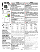
DESCRIZIONE DELLE PARTI
PARTS DESCRIPTION
DESCRIPTION DES PIÈCES
A. Pulsante
PROG
/ Reset
B. Etichetta QR Code
C. Dip-switch a 4 vie
D. Tamper
E. Morsettiera bus
F. Connettore Ethernet RJ45
G. Led stato impianto/Reset Parametri
Dip
-
switch
Utilizzo
DIP 1 Non usato
DIP 2 Non usato
DIP 3 Non usato
DIP 4 Tamper
Legenda Figura 1:
A
B
C
D
E
G
F
A. Reset and Programming (
PROG
) button
B. QR Code label
C. 4-way dip-switch
D. Tamper
E. Terminal board for bus
F. Ethernet RJ45 connector
G. Led system status/Reset Parameter
Dip
-
switch
Use
DIP 1 Not used
DIP 2 Not used
DIP 3 Not used
DIP 4 Tamper
Legend Figure 1:
Figura 1 - Figure 1 - Figure 1
A. Bouton de RAZ et programmation (
PROG
)
B. Etiquette QR Code
C. Commutateur DIP à 4 voies
D. Tamper
E. Bornier bus
F. Connecteur Ethernet RJ45
G. Led état système/RAZ des paramètres
Dip
-
switch
Utilisation
DIP 1 Pas utilisé
DIP 2 Pas utilisé
DIP 3 Pas utilisé
DIP 4 Tamper
Légende Figure 1:

12 IT500CLOUD
ALLOGGIAMENTO NEL CONTENITORE OPZIONALE CP/EP500
LOCATION IN THE OPTIONAL CP/EP500 BOX
LOGEMENT DANS LE BOITIER OPTIONNEL CP/EP500
4
5
6
3
2
1
Figura 2 - Figure 2 - Figure 2

IT500CLOUD 13
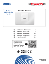
ALLOGGIAMENTO NELLA CENTRALE MP500/8
LOCATION IN THE MP500/8 CONTROL PANEL
LOGEMENT DANS LA CENTRALE MP500/8
Alloggiamenti
Dispositivo
C
Espansione filare EP508 o radio ER600 o IT500CLOUD
D
Espansione filare EP508 o IT500CLOUD
Location Device
C Wired expansion EP508 or radio ER600 or IT500CLOUD
D Wired expansion EP508 or IT500CLOUD
Logement
Dispositif
C
Extension filaire EP508 ou radio ER600 ou IT500CLOUD
D
Extension filaire EP508 ou IT500CLOUD
Fondo box centrale MP500/8
Box bottom of the MP500/8 control panel
Fond de la boîte de la centrale MP500/8
Figura 3 - Figure 3 - Figure 3

14 IT500CLOUD
ESEMPIO SCHEMA DI COLLEGAMENTO CON CENTRALE MP500/8
EXAMPLE CONNECTION DIAGRAM WITH MP500/8 CONTROL
PANEL
EXEMPLE DE DIAGRAMME DE CONNEXION AVEC CENTRALE
MP500/8
DICHIARAZIONE DI CONFORMITÀ UE SEMPLIFICATA
Il fabbricante, URMET S.p.A., dichiara che il tipo di apparecchiatura radio
Interfaccia IT500CLOUD è conforme alla direttiva 2014/53/UE.
Il testo completo della dichiarazione di conformità UE è disponibile al seguente indirizzo Internet:
www.elkron.com
SIMPLIFIED EU DECLARATION OF CONFORMITY
Hereby, Urmet S.p.A. declares that the radio equipment type
IT500CLOUD Interfaces is in compliance with Directive 2014/53/UE.
The full text of the EU declaration of conformity is available at the following internet address:
www.elkron.com
DECLARATION UE DE CONFORMITE SIMPLIFIEE
Le soussigné, Urmet S.p.A., déclare que l’équipement radioélectrique du type
Interface IT500CLOUD est conforme à la directive 2014/53/UE.
Le texte complet de la déclaration UE de conformité est disponible à l'adresse internet suivante :
www.elkron.com
MP500/8
Figura 4 - Figure 4 - Figure 4

IT500CLOUD 15
ITALIANO
DIRETTIVA 2012/19/UE DEL PARLAMENTO EUROPEO E DEL CONSIGLIO del 4
luglio 2012 sui rifiuti di apparecchiature elettriche ed elettroniche (RAEE)
Il simbolo del cassonetto barrato riportato sull’apparecchiatura o sulla sua confezione
indica che il prodotto alla fine della propria vita utile deve essere raccolto
separatamente dagli altri rifiuti.
L’utente dovrà, pertanto, conferire l’apparecchiatura giunta a fine vita agli idonei centri comunali di
raccolta differenziata dei rifiuti elettrotecnici ed elettronici. In alternativa alla gestione autonoma è
possibile consegnare l’apparecchiatura che si desidera smaltire al rivenditore, al momento
dell’acquisto di una nuova apparecchiatura di tipo equivalente. Presso i rivenditori di prodotti
elettronici con superficie di vendita di almeno 400 m2 è inoltre possibile consegnare gratuitamente,
senza obbligo di acquisto, i prodotti elettronici da smaltire con dimensione massima inferiore a 25
cm. L’adeguata raccolta differenziata per l’avvio successivo dell’apparecchiatura dismessa al
riciclaggio, al trattamento e allo smaltimento ambientalmente compatibile contribuisce ad evitare
possibili effetti negativi sull’ambiente e sulla salute e favorisce il reimpiego e/o riciclo dei materiali
di cui è composta l’apparecchiatura.
ENGLISH
DIRECTIVE 2012/19/EU OF THE EUROPEAN PARLIAMENT AND OF THE COUNCIL of
4 July 2012 on waste electrical and electronic equipment (WEEE)
The symbol of the crossed-out wheeled bin on the product or on its packaging indicates
that this product must not be disposed of with your other household waste. Instead, it is
your responsibility to dispose of your waste equipment by handing it over to a
designated collection point for the recycling of waste electrical and electronic equipment. The
separate collection and recycling of your waste equipment at the time of disposal will help to
conserve natural resources and ensure that it is recycled in a manner that protects human health
and the environment.
For more information about where you can drop off your waste equipment for recycling, please
contact your local city office, your household waste disposal service or the shop where you
purchased the product.
FRANÇAIS
DIRECTIVE EUROPEENNE 2012/19/UE du 4 juillet 2012 relatif aux déchets
d'équipements électriques et électroniques (DEEE)
Le symbole de la poubelle sur roues barrée d'une croix présent sur le produit ou sur
son emballage indique que ce produit ne doit pas être éliminé avec vos autres déchets
ménagers.
Au lieu de cela, il est de votre responsabilité de vous débarrasser de vos équipements usagés en
les remettant à un point de collecte spécialisé pour le recyclage des déchets des équipements
électriques et électroniques (DEEE). La collecte et le recyclage séparés de vos équipements
usagés au moment de leur mise au rebut aidera à conserver les ressources naturelles et à
assurer qu'elles sont recyclées d'une manière qui protège la santé humaine et l'environnement.
Pour plus d'informations sur les lieux de collecte où vous pouvez déposer vos équipements
usagés pour le recyclage, veuillez contacter votre revendeur, votre service local d'élimination des
ordures ménagères.

16 IT500CLOUD
ELKRON
Tel. +39 011.3986711 - Fax +39 011.3986703
www.elkron.com
–
mail to: info@elkron.it
ELKRON è un marchio commerciale di URMET S.p.A.
ELKRON is trademark of URMET S.p.A.
ELKRON est une marque commerciale d’URMET S.p.A.
Via Bologna, 188/C - 10154 Torino (TO) – Italy www.urmet.com
Made in
ITALY
1/16