GAI-Tronics HUBBCOM™ Dual-Port Flush-Mount Smart Controllers Guide d'installation
- Taper
- Guide d'installation

Pub. 42004-533G
G A I - T R O N I C S ®
A H U B B E L L C O M P A N Y
HUBBCOM™ GSC3100/GSC4100
Dual-Port Flush-Mount Smart Controllers
TA B L E O F CO N T E N T S
GAI-TRONICS 3030 KUTZTOWN RD. READING, PA 19605 USA
610-777-1374 ◼ 800-492-1212 ◼ Fax: 610-796-5954
VISIT WWW.GAI-TRONICS.COM FOR PRODUCT LITERATURE AND MANUALS
Confidentiality Notice .....................................................................................................................1
General Information .......................................................................................................................1
Important Safety Instructions .........................................................................................................1
Important Safety Instructions................................................................................................................ 1
Security Hardware ..........................................................................................................................3
Installation ......................................................................................................................................3
Flush-Mount Installations ...................................................................................................................... 3
Surface Mount Installations ................................................................................................................... 4
Wiring ...................................................................................................................................................... 5
RTU Input/Output ................................................................................................................................. 5
RS-485/Weigand and External Speaker Connections ........................................................................... 6
Ethernet ................................................................................................................................................. 6
24 V DC Power ..................................................................................................................................... 7
Antenna ................................................................................................................................................. 7
Service and Spare Parts ..................................................................................................................7
Reference Documents .....................................................................................................................7
Specifications ..................................................................................................................................7
Approvals .........................................................................................................................................8

Pub. 42004-533G
G A I - T R O N I C S ®
A H U B B E L L C O M P A N Y
HUBBCOM™ GSC3100/GSC4100
Dual-Port Flush-Mount Smart Controllers
GAI-TRONICS 3030 KUTZTOWN RD. READING, PA 19605 USA
610-777-1374 ◼ 800-492-1212 ◼ Fax: 610-796-5954
VISIT WWW.GAI-TRONICS.COM FOR PRODUCT LITERATURE AND MANUALS
Confidentiality Notice
This installation manual contains sensitive business and technical information that is confidential and
proprietary to GAI-Tronics. GAI-Tronics retains all intellectual property and other rights in or to the
information contained herein, and such information may only be used in connection with the operation of
your GAI-Tronics product or system. This manual may not be disclosed in any form, in whole or in part,
directly or indirectly, to any third party.
General Information
This guide covers the installation of the HUBBCOM Dual-Port Flush-Mount Smart Controller, Models
GSC3100 and GSC4100. The Model GSC3100 Smart Controller includes a handset. The Model
GSC4100 Smart Controller is designed for hands-free operation and is not equipped with a handset (see
Figure 1)). See the GAI-Tronics website at https://www.gai-tronics.com for applications, system
specifications, warranty information, and the GUDA (GAI-Tronics Universal Device Application).
HUBBCOM smart controllers require configuration when placed into service. Use the GUDA (GAI-
Tronics Universal Device Application) software to configure the smart controller for its intended purpose.
Pub. 42004-531 provides instructions to obtain, install, and run the GUDA software. Refer to Pub.
42004-551 for information on HUBBCOM smart controller configuration parameters (see the Reference
Documents section).
Important Safety Instructions
Important Safety Instructions
• Read, follow, and retain instructions—Read and follow all safety and operating instructions before
installing or operating the unit. Retain instructions for future reference.
• Heed warnings—Adhere to all warnings on the unit and in the operating instructions.
• Attachments—Do not use attachments not recommended by the product manufacturer, as they may
cause hazards.
• Servicing—Do not attempt to service this unit. Opening or removing covers may expose dangerous
voltage or other hazards. Refer all servicing to qualified service personnel.
ATTENTION
—Install equipment without modification and according to all applicable local,
national, and international electrical codes. North America - Consult the
National Electrical Code (NFPA 70), Canadian Standards Association (CSA
22.1), and local codes for specific requirements regarding your installation.
Install Class 2 circuit wiring in accordance with the NEC.

Pub. 42004-533G
HUBBCOM™ GSC3100/GSC4100 Dual-Port Flush-Mount Smart Controllers Page 2 of 8
P:\Standard IOMs - Current Release\42004 Instr. Manuals\42004-533G.docx
03/21
Only trained, qualified, and competent personnel must install these devices. Installation must comply
with state and national regulations, as well as safety practices for this type of equipment.
WARNING
—Use only 24 V dc power supplies that conform to UL/CSA/CE Class II, Double
Insulated supplies with over voltage and short circuit protection. Use only a dc
source with a 50-watt maximum output or fuse the supply with a 2-amp fuse.
EMI standards to Class B.
• Onderhoud—Probeer dit apparaat niet zelf te repareren. Het openen of verwijderen van afdekkingen
kan u blootstellen aan gevaarlijke spanning of andere gevaren. Laat alle onderhoud over aan bevoegd
onderhoudspersoneel.
• HUBBCOM Smart Controllers zijn alleen bedoeld voor gebruik binnenshuis.
AANDACHT
—Gebruik alleen 24 VDC-voedingen die voldoen aan UL / CSA / CE Klasse II,
dubbel geïsoleerde voedingen met overspanning en kortsluitbeveiliging.
Gebruik alleen een DC-bron met een maximale output van 50 W of fuseer de
voeding met een 2-ampère zekering. EMI-normen voor klasse B.
• Dépannage—N'essayez pas de réparer cet appareil vous-même. Ouvrir ou retirer les capots peut
vous exposer à des tensions dangereuses ou à d'autres dangers. Confiez toute réparation à un
personnel qualifié.
• Les contrôleurs intelligents HUBBCOM sont conçus pour une utilisation en intérieur uniquement.
ATTENTION
—Utilisez uniquement des alimentations 24 Vcc conformes à UL / CSA / CE
Classe II, des alimentations à double isolation avec protection contre les
surtensions et les courts-circuits. Utilisez uniquement une source cc avec une
sortie maximale de 50 watts ou fusionnez l’alimentation avec un fusible de 2
ampères. Normes EMI à la classe B.
• Manutenzione—non tentare di riparare l'unità da soli. L'apertura o la rimozione dei coperchi
potrebbero esporre a tensioni pericolose o altri rischi. Rivolgersi a personale qualificato per
l'assistenza.
• Gli HUBBCOM Smart Controller sono progettati esclusivamente per uso interno.
AVVERTIMENTO
—Utilizzare solo alimentatori a 24 V cc conformi a UL / CSA / CE Classe II,
alimentatori a doppio isolamento con protezione da sovratensione e
cortocircuito. Utilizzare solo una fonte di corrente continua con un'uscita
massima di 50 watt o collegare l'alimentazione con un fusibile da 2 A.
Standard EMI per la classe B.
• Mantenimiento—no intente reparar esta unidad por sí mismo. Abrir o quitar las cubiertas puede
exponerlo a un voltaje peligroso u otros peligros. Remita todo el servicio a personal de servicio
calificado.
• Los controladores inteligentes HUBBCOM están diseñados para uso en interiores solamente.
ADVERTENCIA
—Utilice solo fuentes de alimentación de 24 V cc que cumplan con UL / CSA /
CE Clase II, fuentes con doble aislamiento con sobretensión y protección
contra cortocircuitos. Utilice solo una fuente de CC con una salida máxima
de 50 vatios o fusione la fuente con un fusible de 2 amperios. Estándares
EMI a Clase B.

Pub. 42004-533G
HUBBCOM™ GSC3100/GSC4100 Dual-Port Flush-Mount Smart Controllers Page 3 of 8
P:\Standard IOMs - Current Release\42004 Instr. Manuals\42004-533G.docx
03/21
Security Hardware
The HUBBCOM smart controllers described in this manual are vandal resistant. Security screws attach
the front panel of each smart controller to its enclosure. Use a GAI-Tronics Model 233-001 security
screwdriver or Torx T-25 security head tip (sold separately) to install the telephone.
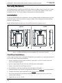
Installation
Flush mount HUBBCOM smart controllers in a wall or stanchion using the included backbox or surface
mount them using a GAI-Tronics Model 236 Series or Model 238-001 Stainless-Steel Surface-Mount
Enclosure (sold separately).
NOTE: HUBBCOM devices require access to an NTP (network time protocol) server.
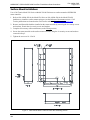
Figure 1. HUBBCOM Model GSC3100 and Model GSC4100 Smart Controllers
Flush-Mount Installations
Use the supplied backbox when mounting the HUBBCOM smart controller in a GAI-Tronics Model 234
Series Tower and for flush-mount installations:
1. Remove the backbox from the smart controller by removing the six #10-32 security screws and
washers holding them together.
2. Remove a tapered plug from one of the rear cable entry holes in the backbox.
3. Install a cable strain relief cable fitting to the box.
4. Feed the Ethernet cable and all additional cables through the cable fitting.
5. Mount the backbox to the structure using appropriate hardware (see Figure 3 for cutout dimensions).
6. Complete all necessary cable terminations (see the Wiring section).
7. Secure the smart controller to the backbox mounting flanges using the six security screws with
washers removed in Step 1.
8. Tighten the screws to 10–12 in∙lb.

Pub. 42004-533G
HUBBCOM™ GSC3100/GSC4100 Dual-Port Flush-Mount Smart Controllers Page 4 of 8
P:\Standard IOMs - Current Release\42004 Instr. Manuals\42004-533G.docx
03/21
Surface Mount Installations
Use a GAI-Tronics Model 236 Series or Model 238-001 Enclosure to surface mount the HUBBCOM
smart controller:
1. Refer to Pub. 42004-285 for the Model 236 Series or Pub. 42004-434 for the Model 238-001
backboxes to install the surface-mount enclosure (see the Reference Documents section). GAI-
Tronics publications are located on the GAI-Tronics website at https://www/gai-tronics.com.
2. Remove and discard the backbox installed on the smart controller by removing the six security screws
and washers. Retain the six security screws and washers.
3. Complete all necessary cable terminations (see the Wiring section).
4. Secure the smart controller to the surface-mount enclosure using the six security screws and washers
removed in Step 2.
5. Tighten the screws to 10–12 in∙lb.
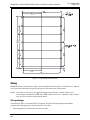
Figure 2. Flush-Mount Smart Controller Back Box Mounting Details

Pub. 42004-533G
HUBBCOM™ GSC3100/GSC4100 Dual-Port Flush-Mount Smart Controllers Page 5 of 8
P:\Standard IOMs - Current Release\42004 Instr. Manuals\42004-533G.docx
03/21
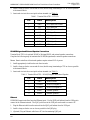
Figure 3. Flush-Mount Cutout Details
Wiring
HUBBCOM smart controllers have quick release terminal blocks that accept 18–24 AWG wires. Release
wires from the terminal block by pressing the quick release button above the terminal.
NOTE: Two clamp on ferrite cores are supplied with the smart controller. Double wrap all wires
terminating to terminal blocks TB1 and/or TB2 around a ferrite core. Install the clamp on ferrite
cores as close as possible to the terminal blocks.
RTU Input/Output
Terminal block TB1 is for optional RTU I/O (Remote Terminal Unit Input/Output) functionality.
Complete the following steps to terminate the RTU I/O cables:
1. Install appropriately sized ferrules onto the wire ends.

Pub. 42004-533G
HUBBCOM™ GSC3100/GSC4100 Dual-Port Flush-Mount Smart Controllers Page 6 of 8
P:\Standard IOMs - Current Release\42004 Instr. Manuals\42004-533G.docx
03/21
2. Install a clamp on ferrite core around all wires (double wrap) terminating to TB1 as close as possible
to the terminal block.
3. Insert each wire into the correct quick release terminal (see Table 1).
Table 1. Terminal Block TB1—RTU I/O
Pin
Label
Description
1
GND
RTU Input One Ground
2
IN1
RTU Input One
3
GND
RTU Input Two Ground
4
IN2
RTU Input Two
5
OUT1+
RTU Output One +
6
OUT1(−)
RTU Output One −
7
OUT2(−)
RTU Output Two −
8
OUT2+
RTU Output Two +
RS-485/Weigand and External Speaker Connections
Terminal block TB2 is for optional RS-485 or Weigand D0/D1 and external speaker connections.
Complete the following steps to terminate the RS-485/Weigand and/or external speaker connections:
NOTE: Smart controllers with external speakers require external 24 V dc power.
1. Install appropriately sized ferrules onto the wire ends.
2. Install a clamp on ferrite core around all wires (double wrap) terminating to TB2 as close as possible
to the terminal block.
3. Insert each wire into the correct quick release terminal (see Table 2).
Table 2. Terminal Block TB2—RS-485/Weigand and External Speaker
Pin
Label
Description
1
GND
RS485 Ground
2
RS485B
RS485 B/Weigand D1
3
RS485A
RS485 A/Weigand D0
4
SPKR−
External Speaker −
5
SPKR+
External Speaker +
Ethernet
HUBBCOM smart controllers have dual Ethernet ports. Use the RJ45 jack furthest from the USB port to
connect to the Ethernet network. The RJ45 jack closest to the USB port can be used to connect a PC.
1. Plug the Ethernet cable from the network into the RJ45 jack furthest from the USB port.
2. Install a clamp on ferrite core as close as possible to the RJ45 plug.
3. (Optional) Plug an Ethernet cable from a PC into the remaining RJ45 jack.

Pub. 42004-533G
HUBBCOM™ GSC3100/GSC4100 Dual-Port Flush-Mount Smart Controllers Page 7 of 8
P:\Standard IOMs - Current Release\42004 Instr. Manuals\42004-533G.docx
03/21
24 V DC Power
Use external 24 V dc power in place of POE (optional) or for smart controllers with external speaker
hook-ups (required). Complete the following steps to terminate the 24 V dc power source to the smart
controller:
1. Install appropriately sized ferrules onto the wire ends.
2. Insert each wire into the correct quick release terminal (see Table 3).
Table 3. Terminal Block TB3—24 V DC Power
Pin
Label
Description
TB3-1
+24V
24 V dc Positive
TB3-2
GND
Ground
Antenna
Use the provided SMA (Sub-Miniature connector A) coaxial connector to connect an antenna.
NOTE: Connecting a HUBBCOM smart controller via WiFi disables the secondary Ethernet port.
NOTE: Use a customer-supplied antenna in flush-mount installations. FCC, IC, ETSI/CE, and TELEC
Certified with PCB, Dipole, Chip, and PIFA Antennae. GAI-Tronics Kit No. 12840-001
(purchased separately) meets the antenna requirements.
Service and Spare Parts
Contact a regional service center for assistance if the equipment requires service or spare parts. A return
authorization number (RA#) will be issued for required service. Ship equipment prepaid to GAI-Tronics
with an RA# and a purchase order number. Repair or replacement is made in accordance with GAI-
Tronics’ warranty policy if the equipment is under warranty. Please include a written explanation of all
defects to assist our technicians in their troubleshooting efforts. Call 800-492-1212 inside the USA or
610-777-1374 outside the USA for help with identifying the regional service center closest to you.
Reference Documents
GAI-Tronics’ publications are located on the GAI-Tronics website at https://www/gai-tronics.com.
GAI-Tronics Universal Device Application .................................................................................. 42004-531
HUBBCOM Device Configuration Guide ..................................................................................... 42004-551
Model 236-001 Series Surface-Mount Telephone Enclosures ....................................................... 42004-285
238-001 Series Stainless Steel Surface-Mount Enclosures ............................................................ 42004-434
Specifications
Wi-Fi operating frequency range ........................................................................................ 2.412–2.462 GHz
Temperature Range ........................................................................................................32–122 °F (0–50 °C)

Pub. 42004-533G
HUBBCOM™ GSC3100/GSC4100 Dual-Port Flush-Mount Smart Controllers Page 8 of 8
P:\Standard IOMs - Current Release\42004 Instr. Manuals\42004-533G.docx
03/21
Approvals
Compliance to Standard
CE
EMC emissions to Class B ....................................................................... EN55032/FCC Part15B/ICES-003
Immunity .......................................................................................................................................... EN55035
Assessment risk of exposure ............................................................................................................ EN62311
Product Safety Assessment ................................................................................................... UL/IEC62368-1
Contains FCC ID: Z64-WL18DBMOD and IC: 4511-WL18DBMOD
NOTE: This equipment has been tested and found to comply with the limits for a Class B digital device, pursuant
to part 15 of the FCC rules. These limits are designed to provide reasonable protection against harmful
interference in a residential installation. This equipment generates, uses, and can radiate radio frequency
energy and, if not installed and used in accordance with the instructions, may cause harmful interference to
radio communications. However, there is no guarantee that interference will not occur in a particular
installation. If this equipment does cause harmful interference to radio or television reception, which can
be determined by turning the equipment off and on, the user is encouraged to try to correct the interference
by one or more of the following measures:
• reorient or relocate the receiving antenna.
• increase the separation between the equipment and receiver.
• connect the equipment into an outlet on a circuit different from that to which the receiver is connected.
• consult the dealer or an experienced radio/tv technician for help.

(Rev. 10/06)
Warranty
Equipment. GAI-Tronics warrants for a period of one (1) year from the date of shipment, that any
GAI-Tronics equipment supplied hereunder shall be free of defects in material and workmanship, shall
comply with the then-current product specifications and product literature, and if applicable, shall be fit
for the purpose specified in the agreed-upon quotation or proposal document. If (a) Seller’s goods prove
to be defective in workmanship and/or material under normal and proper usage, or unfit for the purpose
specified and agreed upon, and (b) Buyer’s claim is made within the warranty period set forth above,
Buyer may return such goods to GAI-Tronics’ nearest depot repair facility, freight prepaid, at which time
they will be repaired or replaced, at Seller’s option, without charge to Buyer. Repair or replacement shall
be Buyer’s sole and exclusive remedy. The warranty period on any repaired or replacement equipment
shall be the greater of the ninety (90) day repair warranty or one (1) year from the date the original
equipment was shipped. In no event shall GAI-Tronics warranty obligations with respect to equipment
exceed 100% of the total cost of the equipment supplied hereunder. Buyer may also be entitled to the
manufacturer’s warranty on any third-party goods supplied by GAI-Tronics hereunder. The applicability
of any such third-party warranty will be determined by GAI-Tronics.
Services. Any services GAI-Tronics provides hereunder, whether directly or through subcontractors,
shall be performed in accordance with the standard of care with which such services are normally
provided in the industry. If the services fail to meet the applicable industry standard, GAI-Tronics will
re-perform such services at no cost to buyer to correct said deficiency to Company's satisfaction provided
any and all issues are identified prior to the demobilization of the Contractor’s personnel from the work
site. Re-performance of services shall be Buyer’s sole and exclusive remedy, and in no event shall GAI-
Tronics warranty obligations with respect to services exceed 100% of the total cost of the services
provided hereunder.
Warranty Periods. Every claim by Buyer alleging a defect in the goods and/or services provided
hereunder shall be deemed waived unless such claim is made in writing within the applicable warranty
periods as set forth above. Provided, however, that if the defect complained of is latent and not
discoverable within the above warranty periods, every claim arising on account of such latent defect shall
be deemed waived unless it is made in writing within a reasonable time after such latent defect is or
should have been discovered by Buyer.
Limitations / Exclusions. The warranties herein shall not apply to, and GAI-Tronics shall not be
responsible for, any damage to the goods or failure of the services supplied hereunder, to the extent
caused by Buyer’s neglect, failure to follow operational and maintenance procedures provided with the
equipment, or the use of technicians not specifically authorized by GAI-Tronics to maintain or service the
equipment. THE WARRANTIES AND REMEDIES CONTAINED HEREIN ARE IN LIEU OF AND
EXCLUDE ALL OTHER WARRANTIES AND REMEDIES, WHETHER EXPRESS OR IMPLIED BY
OPERATION OF LAW OR OTHERWISE, INCLUDING ANY WARRANTIES OF
MERCHANTABILITY OR FITNESS FOR A PARTICULAR PURPOSE.
Return Policy
If the equipment requires service, contact your Regional Service Center for a return authorization number
(RA#). Equipment should be shipped prepaid to GAI-Tronics with a return authorization number and a
purchase order number. If the equipment is under warranty, repairs or a replacement will be made in
accordance with the warranty policy set forth above. Please include a written explanation of all defects to
assist our technicians in their troubleshooting efforts.
Call 800-492-1212 (inside the USA) or 610-777-1374 (outside the USA) for help identifying the
Regional Service Center closest to you.
-
 1
1
-
 2
2
-
 3
3
-
 4
4
-
 5
5
-
 6
6
-
 7
7
-
 8
8
-
 9
9
-
 10
10


GAI-Tronics HUBBCOM™ Dual-Port Flush-Mount Smart Controllers Guide d'installation
- Taper
- Guide d'installation
dans d''autres langues
Documents connexes

Autres documents
-
Eaton DG1-357D6FB-C21C Communications Manual
-
Güde 5 T UG Le manuel du propriétaire
-
Spektrum SPMCP Le manuel du propriétaire
-
Agri-Fab 45-04621 Le manuel du propriétaire
-
-
Philips SWV4132W/10 Product Datasheet
-
 iTronics 700 Manuel utilisateur
-
Lego 42004 Technic Building Instructions
-
Taurus BABIPLUS DUAL CP Le manuel du propriétaire
