

UltiMate 3000 Series:
VWD-3100 and VWD-3400RS Variable Wavelength Detectors
Operating Instructions

UltiMate 3000 Series:
VWD-3100 and VWD-3400RS Variable Wavelength Detectors
Operating Instructions Page I
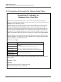
Declaration of Conformity
(Original Declaration of Conformity)
Product: Thermo Scientific Dionex UltiMate 3000 - Detector
Types: VWD-3100 and VWD-3400RS
Dionex Softron GmbH herewith declares conformity of the above products with
the respective requirements of the following regulations:
• Low-Voltage Directive 2006/95/EC
• EMC Directive 2004/108/EC
The electrical safety of the products was evaluated based on the following
standard:
• DIN EN 61010-1:2010
Safety requirements for electrical equipment for measurement, control and
laboratory use, Part 1: General Requirements
The Electromagnetic Compatibility (EMC) of the products was evaluated based on
the following standard:
• DIN EN 61326:2006
Electrical equipment for measurement, control and laboratory use
EMC Requirements
This declaration is issued for the manufacturer
Dionex Softron GmbH
Part of Thermo Fisher Scientific Inc.
Dornierstraße 4
D-82110 Germering
by the Managing Director, Rüdiger Obst, and
the Vice President HPLC, Fraser McLeod.
September 2, 2013

UltiMate 3000 Series:
VWD-3100 and VWD-3400RS Variable Wavelength Detectors
Page II Operating Instructions

UltiMate 3000 Series:
VWD-3100 and VWD-3400RS Variable Wavelength Detectors
Operating Instructions Page i
Table of Content
1 Introduction ................................................................................................................... 1
1.1 How to Use this Manual ............................................................................................ 1
1.2 Safety ......................................................................................................................... 3
1.2.1 Symbols on the Instrument and in the Manual .................................................. 3
1.2.2 Safety Precautions .............................................................................................. 5
1.2.3 Consignes de Sécurité ........................................................................................ 9
1.3 Intended Use ............................................................................................................ 13
1.4 Federal Communications Commission (FCC) Note ................................................ 15
2 Overview ...................................................................................................................... 17
2.1 Unit Description ....................................................................................................... 17
2.2 Operating Principle .................................................................................................. 18
2.3 Configurations ......................................................................................................... 20
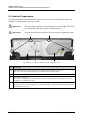
2.4 Interior Components ................................................................................................ 22
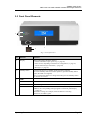
2.5 Front Panel Elements ............................................................................................... 23
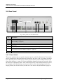
2.6 Rear Panel ................................................................................................................ 24
2.6.1 Power Switch ................................................................................................... 24
2.6.2 Fuse Cartridge .................................................................................................. 25
2.6.3 USB Port .......................................................................................................... 25
2.6.4 Digital I/O ........................................................................................................ 25
2.6.5 Analog Outputs (Optional) .............................................................................. 25
2.6.6 pH and Conductivity Monitor (optional) ......................................................... 26
2.7 Fluid Connections .................................................................................................... 27
2.8 Flow Cells ................................................................................................................ 28
2.9 Lamps ....................................................................................................................... 29
2.10 Leak Sensor .......................................................................................................... 30
2.11 Detector Control .................................................................................................. 30
2.12 System Wellness, Predictive Performance, and Diagnostics ............................... 32
3 Installation ................................................................................................................... 33
3.1 Facility Requirements .............................................................................................. 33
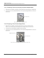
3.2 Unpacking ................................................................................................................ 33
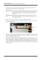
3.3 Positioning the Detector in the UltiMate 3000 System ........................................... 35
3.4 Connecting the Detector .......................................................................................... 37
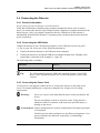
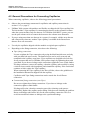
3.4.1 General Information ......................................................................................... 37
3.4.2 Connecting the USB Cable .............................................................................. 37
3.4.3 Connecting the Power Cord ............................................................................. 37
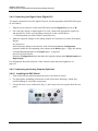
3.4.4 Connecting the Signal Cable (Digital I/O) ...................................................... 38
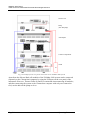
3.4.5 Connecting the Analog Outputs (Optional) ..................................................... 38
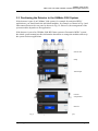
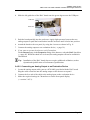
3.4.6 Connecting the PCM-3000 (optional) .............................................................. 40
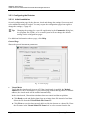
3.5 Setting Up the Detector in Chromeleon ................................................................... 41
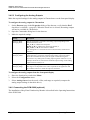
3.5.1 Loading the USB Driver for the Detector ........................................................ 41

UltiMate 3000 Series:
VWD-3100 and VWD-3400RS Variable Wavelength Detectors
Page ii Operating Instructions
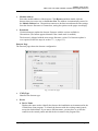
3.5.2 Installing the Detector ...................................................................................... 43
3.5.3 Configuring the Detector ................................................................................. 44
3.6 Setting Up the Detector in DCMSLink .................................................................... 48
4 Preparation for Operation (Startup) ........................................................................ 49
4.1 Overview of Actions ................................................................................................ 49
4.2 General Precautions for Connecting Capillaries ...................................................... 50
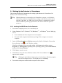
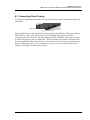
4.3 Connecting Drain Tubing......................................................................................... 51
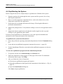
4.4 Equilibrating the System .......................................................................................... 52
5 Operation and Maintenance ...................................................................................... 55
5.1 Power-Up ................................................................................................................. 56
5.2 Status Screens .......................................................................................................... 57
5.3 Detector Control ....................................................................................................... 58
5.3.1 Operation from the Front Panel Display .......................................................... 58
5.3.2 Chromeleon Software ...................................................................................... 58
5.4 Display Screens (Function Keys and Menus) .......................................................... 64
5.4.1 Showing the Function Keys ............................................................................. 64
5.4.2 Detector Menus ................................................................................................ 66
5.5 Information for Operating the Detector ................................................................... 73
5.5.1 General Notes ................................................................................................... 73
5.5.2 Setting the Wavelengths................................................................................... 78
5.5.3 Turning on the Lamps ...................................................................................... 78
5.5.4 Monitoring the Lamp Intensity ........................................................................ 79
5.5.5 Starting and Stopping Data Acquisition........................................................... 80
5.5.6 Setting the Display Mode ................................................................................. 82
5.5.7 Leak Detection ................................................................................................. 82
5.5.8 Recording the Temperature Signals ................................................................. 83
5.5.9 Adjusting the Screen Brightness and Contrast ................................................. 83
5.5.10 SmartStartup and SmartShutdown ............................................................... 83
5.6 Special Functions in Chromeleon ............................................................................ 84
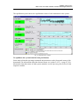
5.6.1 Optimizing the Detector Performance ............................................................. 84
5.6.2 Recording Absorbance Spectra ........................................................................ 88
5.6.3 Predictive Performance .................................................................................... 89
5.6.4 Detector Diagnostics ........................................................................................ 90
5.6.5 Operational Qualification and Performance Qualification .............................. 91
5.7 Shutting Down the Detector ..................................................................................... 92
5.8 Routine and Preventive Maintenance ...................................................................... 94
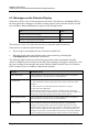
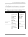
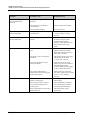
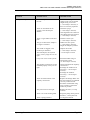
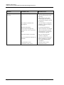
6 Troubleshooting .......................................................................................................... 95
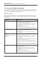
6.1 Overview .................................................................................................................. 95
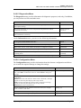
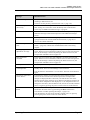
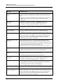
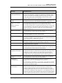
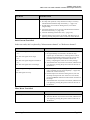
6.2 Messages on the Detector Display ........................................................................... 96
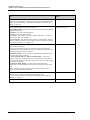
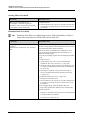
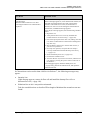
6.3 Chromeleon Diagnostics Messages ....................................................................... 104
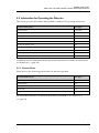
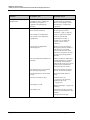
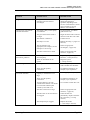
6.4 Operating Problems................................................................................................ 109

UltiMate 3000 Series:
VWD-3100 and VWD-3400RS Variable Wavelength Detectors
Operating Instructions Page iii
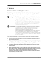
7 Service ........................................................................................................................ 115
7.1 General Notes and Safety Precautions ................................................................... 115
7.2 Wavelength Calibration and Verification .............................................................. 117
7.3 Lamp ...................................................................................................................... 119
7.3.1 Replacing the Deuterium Lamp ..................................................................... 121
7.3.2 Installing or Replacing the Tungsten Lamp ................................................... 123
7.4 Flow Cell ................................................................................................................ 125
7.4.1 Dummy Flow Cell ......................................................................................... 125
7.4.2 Cleaning the Flow Cell .................................................................................. 125
7.4.3 Replacing the Flow Cell ................................................................................ 126
7.5 Drying the Leak Sensor ......................................................................................... 131
7.6 Replacing the Main Power Fuses........................................................................... 132
7.7 Updating the Detector Firmware ........................................................................... 133
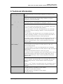
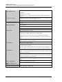
8 Technical Information .............................................................................................. 135
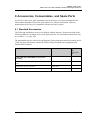
9 Accessories, Consumables, and Spare Parts .......................................................... 139
9.1 Standard Accessories ............................................................................................. 139
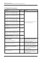
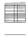
9.2 Optional Accessories ............................................................................................. 140
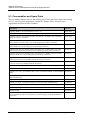
9.3 Consumables and Spare Parts ................................................................................ 142
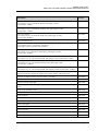
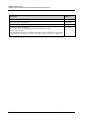
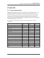
10 Appendix .................................................................................................................... 145
10.1 Common Mobile Phases .................................................................................... 145
10.2 Digital I/O .......................................................................................................... 147
10.3 Declaration of Conformity for Holmium Oxide Filters ..................................... 148
11 Index ........................................................................................................................... 149

UltiMate 3000 Series:
VWD-3100 and VWD-3400RS Variable Wavelength Detectors
Page iv Operating Instructions

UltiMate 3000 Series:
VWD-3100 and VWD-3400RS Variable Wavelength Detectors
Operating Instructions Page 1
1 Introduction
1.1 How to Use this Manual
The layout of this manual is designed to provide quick reference to the sections of interest
to the reader. However, in order to obtain a full understanding of your Thermo Scientific™
Dionex™ detector, Thermo Fisher Scientific recommends that you review the manual
thoroughly before beginning operation.
Almost all descriptions in the manual apply to the following variable wavelength detectors in
the UltiMate 3000 series:
• VWD-3100
• VWD-3400RS
The following conventions apply to the descriptions throughout this manual:
• The term "the detector" or "the device" is used throughout the manual. If some detail
applies to only one version, the detector is identified by name.
• If not otherwise stated, the descriptions for the Viper™ capillary connections apply also
to the nanoViper™ and possible other Viper capillary connections.
• The device configuration may vary. Therefore, not all descriptions necessarily apply to
your particular module.
• The representation of a component in this manual may be slightly different from the real
component. However, this does not influence the descriptions.
• The descriptions in this manual refer to firmware version 3.70 and Chromeleon™ 6.80
Service Release 13. If you want to operate the detector from Chromeleon 7, note the
information on page 30.
This manual is provided "as is". Every effort has been made to supply complete and
accurate information and all technical specifications have been developed with the utmost
care. The information contained in this manual should not be construed as a commitment
by Thermo Fisher Scientific. Thermo Fisher Scientific assumes no responsibility for any
errors that may appear in this document that is believed to be complete and accurate at the
time of publication and, in no event, shall Thermo Fisher Scientific be liable for incidental
or consequential damages in connection with or arising from the use of this document. We
appreciate your help in eliminating any errors that may appear in this document.
The information contained in this document is subject to change without notice.

UltiMate 3000 Series:
VWD-3100 and VWD-3400RS Variable Wavelength Detectors
Page 2 Operating Instructions
All rights reserved, including those for photomechanical reproduction and storage on
electronic media. No part of this publication may be copied or distributed, transmitted,
transcribed, stored in a retrieval system, or transmitted into any human or computer language,
in any form or by any means, electronic, mechanical, magnetic, manual, or otherwise, or
disclosed to third parties without the express written permission of Thermo Fisher Scientific
Inc.
Trademarks
Analyst is a registered trademark of AB Sciex.
Compass and Hystar are trademarks of Bruker Daltonics.
Empower is a trademark of Waters Corp.
MP35N is a registered trademark of SPS Technologies.
PEEK is a trademark of Victrex PLC.
Windows and Windows Vista are registered trademarks of Microsoft Corp.
All other trademarks are property of Thermo Fisher Scientific Inc. and its subsidiaries.

UltiMate 3000 Series:
VWD-3100 and VWD-3400RS Variable Wavelength Detectors
Operating Instructions Page 3
1.2 Safety
The CE Mark label and cTUVus Mark safety label on the instrument indicate that the
detector is compliant with the related standards.
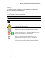
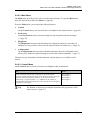
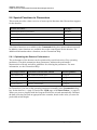
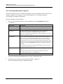
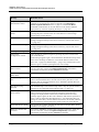
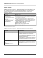
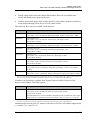
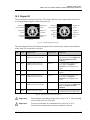
1.2.1 Symbols on the Instrument and in the Manual
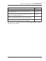
The table shows the symbols used on the detector:
Symbol Description
Alternating current—Courant alternatif
Power supply is on (-)—L'instrument est mis sous tension (-) and Power supply
is off (O)—L'instrument est mis hors tension (O)
Refer to the Operating Instructions to prevent risk of harm to the operator and to
protect the instrument against damage.
Référez-vous à ce manuel pour éviter tout risque de blessure à l'opérateur et/ou
protéger l'instrument contre tout dommage
The deuterium lamp emits UV radiation that is harmful to the eyes and skin.
Therefore, avoid looking directly into the light source. Operate the lamp only in
the detector with the lamp cover installed and never outside the instrument.
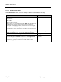
Label according to the "Measures for Administration of the Pollution Control of
Electronic Information Products" (China RoHS) guideline
Étiquette "Measures for Administration of the Pollution Control of Electronic
Information Products" (China RoHS)
WEEE (Waste Electrical and Electronic Equipment) label—For more
information, see the WEEE Information section in the "Installation and
Qualification Documents for Chromatography Instruments" binder.
Étiquette DEEE (Déchets d'Equipements Electriques et Electroniques) —Pour
plus d'informations, référez-vous au chapitre WEEE Information dans le classeur
"Installation and Qualification Documents for Chromatography Instruments".
˜

UltiMate 3000 Series:
VWD-3100 and VWD-3400RS Variable Wavelength Detectors
Page 4 Operating Instructions
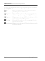
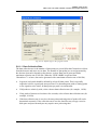
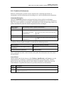
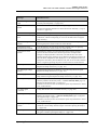
At various points throughout the manual, messages of particular importance are indicated
by certain symbols:
Tip: Indicates general information, as well as information intended to
optimize the performance of the instrument.
Important: Indicates that failure to take note of the accompanying information
could cause wrong results or may result in damage to the instrument.
Important: Indique que ne pas tenir compte de l'information jointe peut conduire
à de faux résultat ou endommager l'instrument.
Warning: Indicates that failure to take note of the accompanying information
may result in personal injury.
Avertissement: Indique que ne pas tenir compte de l'information jointe peut entraîner
des blessures corporelles.

UltiMate 3000 Series:
VWD-3100 and VWD-3400RS Variable Wavelength Detectors
Operating Instructions Page 5
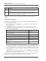
1.2.2 Safety Precautions
When working with analytical instrumentation, you must know the potential hazards of
using chemical solvents.
Tip: Before initial operation of the detector, make yourself familiar with
the contents of this manual.
For the safety precautions in French, see page 9.
Warning: All users of the device must observe the following safety precautions
and all additional safety precautions in this manual to avoid the
possibility of personal injury or damage to the device when
operating the device or carrying out any maintenance or service
procedures.
Observe any warning labels on the device and see the related
sections in these Operating Instructions.
• Protective equipment
When performing any work on or near the HPLC system, wear personal protective
equipment (protective clothing, safety gloves, safety glasses) as required by the hazard of
the mobile phase and sample. For information about the proper handling of a particular
substance and for advice on specific hazards, refer to the material safety data sheet for the
substance you are using. Observe the guidelines of Good Laboratory Practice (GLP).
An eyewash facility and a sink should be close to the device. If any substance splashes on
the eyes or skin, wash the affected area and seek medical attention.
• Hazardous substances
Many organic solvents, mobile phases, and samples are harmful to health. Be sure that
you know the toxic and infectious properties of all substances that you are using. You
may not know the toxic or infectious properties of many substances that you are using. If
you have any doubt about a substance, treat it as if it contains a potentially harmful
substance. For advice on the proper handling of a particular substance, refer to the Safety
Data Sheet (SDS) of the manufacturer. Observe the guidelines of Good Laboratory
Practice (GLP).
Dispose of waste substance in an environmentally safe manner that is consistent with all
local regulations. Do not allow flammable, toxic, and/or infectious substances to
accumulate. Follow a regulated, approved waste disposal program. Never dispose of
flammable, toxic, and/or infectious substances through the municipal sewage system.

UltiMate 3000 Series:
VWD-3100 and VWD-3400RS Variable Wavelength Detectors
Page 6 Operating Instructions
• Hazardous gases
Install the HPLC system in a well-ventilated laboratory. If the mobile phase or sample
includes volatile or flammable solvents, do not allow them to enter the workspace. If the
mobile phase or sample includes volatile or flammable solvents, avoid open flames and
sparks.
• Electrostatic discharge
Discharge of electrostatic energy may lead to sparking and can constitute a fire hazard.
Keep in mind that liquid flowing through capillaries can generate static electricity. This
effect is particularly pronounced in insulating capillaries and with non-conductive
solvents (for example, pure acetonitrile).
Take appropriate measures to prevent the generation of static electricity near the HPLC
system. For example, make sure that the air humidity level in the laboratory is
sufficiently high and provide proper ventilation, wear anti-static clothing or shoes,
prevent accumulation of air bubbles in waste lines, and use grounded waste containers.
Use only non-conductive capillaries to direct solvents into the waste container. With
electrically conductive capillaries, make sure that they are properly grounded.
• Self-ignition of solvents
Do not use solvents for which the self-ignition temperature is below 150 °C. In case of
leakage, these solvents may self-ignite on a hot surface.
• Capillaries, capillary connections, open connections
♦ Capillaries, especially non-metallic capillaries may burst, slip out of their fittings or
may not be screwed in. This may result in substances spraying out of the open
connections.
♦ In an UltiMate 3000 system, some components are made of PEEK™. This polymer
has superb chemical resistance to most organic solvents. However, it tends to swell
when in contact with trichlormethane (CHCl3), dimethyl sulfoxide (DMSO), or
tetrahydrofuran (THF). In addition, it is attacked by concentrated acids, such as,
sulfuric acid and nitric acid or a mixture of hexane, ethyl actate, and methanol. In both
cases, capillaries may start leaking or they can burst. Swelling or attack by
concentrated acids is not a problem with brief flushing procedures.
♦ Do not use tubing that is stressed, bent, kinked, or damaged.
♦ Capillary connections can be contaminated by harmful substances or harmful
substances can escape from open connections.
♦ Some capillaries are made of MP35N®, a nickel-cobalt based alloy. Individuals with
sensitivity to nickel/cobalt may show an allergic reaction from skin contact.
♦ Always wear safety glasses when handling fused silica tubing, for example, during
installation or when cutting capillaries to the length.

UltiMate 3000 Series:
VWD-3100 and VWD-3400RS Variable Wavelength Detectors
Operating Instructions Page 7
• Hot surfaces
♦ During operation, the lamps and the surrounding parts become extremely hot and
remain so for some time after the detector is turned off. To avoid possible injury,
allow sufficient time for the lamp to cool down after turning off the detector. Only
then start with the maintenance and repair work.
♦ Flow cells can become extremely hot during operation. To avoid possible injury,
allow sufficient time for the flow cell to cool down before replacing the cell.
• UV radiation
♦ The deuterium lamp emits UV radiation that is harmful to the eyes and skin. The
deuterium lamp can emit UV radiation from the rear side of the lamp (side of the
connection wires) when it is installed in the detector. Therefore, avoid looking directly
into the light source. Operate the lamp only in the detector with the lamp cover
installed and never outside the instrument. Always turn off the detector and disconnect
the power cord from its source before exchanging the deuterium or tungsten lamp.
To avoid possible injury to the skin, do not reach inside the lamp house. Insert only
the tungsten lamp and no other parts into the lamp house of the detector.
♦ When the flow cell is removed and the lamps are turned on, monochromatic light
emits in the flow cell opening from the opening on the left of the flow cell. The UV
radiation is harmful to the eyes and skin. To avoid possible damage to the eyes and
skin, turn off the detector before replaing the flow cell or wear UV glasses and
appropriate protective clothing.
To avoid possible injury to the skin, do not reach inside the flow cell opening. Insert
only the flow cell and no other parts into the flow cell opening of the detector.
• Disconnect the detector from all power sources before removing the panels. When the
panels are removed, dangerous electrical connections will be exposed. The enclosure
must be opened only by Thermo Fisher Scientific service personnel.
• Always replace blown fuses with original spare part fuses authorized by Thermo Fisher
Scientific.
• Replace faulty communication cables.
• Replace faulty power cords. Never use a power cord other than the power cords provided
for the device.
• Use only the original spare parts and accessories authorized for the device by Thermo
Fisher Scientific.
• When lifting or moving the detector, always lift the unit by the bottom sides or sides. Do
not lift the detector by the front panel door. This may damage the door.
• The open front panel door is not designed to carry weight. Therefore, you should not
place any objects on the open door.
• After operation, rinse out buffers and solutions that form peroxides.

UltiMate 3000 Series:
VWD-3100 and VWD-3400RS Variable Wavelength Detectors
Page 8 Operating Instructions
• Before switching from buffer to organic solution, rinse the analytical system thoroughly
with deionized or HPLC grade water.
• When switching to another solvent, ensure that the new solvent is miscible with the one
contained in the HPLC system. If the solvents are not miscible, the system can be
damaged, for example, by flocculation.
• If a leak occurs, turn off the instrument and remedy the situation immediately.
• Use only standard solvents (HPLC grade) and buffers that are compatible with all parts
that may be exposed to solvents.
• Before interrupting operation for several days or more or when preparing the detector for
transport, observe the precautions for shutting down the detector (→ page 92).
• Do not use the detector in ways other than those described in these Operating
Instructions.
• Keep the operating instructions near the device to be available for quick reference.

UltiMate 3000 Series:
VWD-3100 and VWD-3400RS Variable Wavelength Detectors
Operating Instructions Page 9
1.2.3 Consignes de Sécurité
Si vous utilisez d'instrumentation analytique, vous devez connaître les risques d'utilisation
de produit chimiques.
Veuillez noter : Avant de commencer à utiliser l'instrument, assurez-vous que vous
vous êtes familiarisés avec le contenu de ce manuel.
Avertissement: Toutes les personnes utilisant l’instrument doivent observer les
consignes de sécurité suivantes et dans les autres chapitres de ce
manuel pour éviter une mise en danger de sa personne ou de
dommage à l’instrument pendant l’utilisation et des opérations de
maintenance ou service de l’instrument.
• Equipment de protection
Pour tous les travaux sur le système HPLC ou à proximité, portez l'équipement de
protection personnel (vêtements de protection, gant de sécurité, lunettes de protection)
qui correspond aux risque découlant de la phase mobile et/ou de l'échantillon. Pour les
informations sur la manipulation correcte des composés et des recommandations pour les
situations de risque spécifiques, veuillez consulter la fiche de données de sécurité des
substances que vous utilisez. Veuillez respecter des directives des Bonnes Pratiques de
Laboratoire (BPL).
Une installation permettant de se laver les yeux ainsi qu'un lavabo doivent se trouver à
proximité du système. Si une substance, quelle qu'elle soit, entre en contact avec vos
yeux ou votre peau, rincez abondamment la zone affectée à l’eau, puis.
• Substances dangereuses
De nombreux solvants organiques, phases mobiles et échantillons sont nuisibles à la
santé. Informez-vous de propriétés toxicologiques et infectieuses de toutes les substances
que vous utilisez. Les propriétés toxicologiques et infectieuses de nombreuses substances
peuvent être mal connues. Au moindre doute concernant une substance, traitez-la comme
s'il contenait une substance potentiellement dangereuse. Pour des instructions comment
utiliser correctement des composés particuliers, veuillez consulter à la fiche de données
des sécurités du fabricant respectif. Veuillez respecter des directives des Bonnes
Pratiques de Laboratoire (BPL).
Débarrassez-vous de tous les déchets de substances de manière écologique,
conformément à la règlementation en vigueur au niveau local. Empêchez impérativement
l'accumulation de solvants inflammables, toxiques et/ou infectieux. Suivez un
programme d'élimination des déchets règlementé et approuvé. Ne jetez jamais de
solvants inflammables, toxiques et/ou infectieux dans le système municipal d'évacuation
des eaux usées.

UltiMate 3000 Series:
VWD-3100 and VWD-3400RS Variable Wavelength Detectors
Page 10 Operating Instructions
• Gaz dangereux
Installez le système HPLC dans un laboratoire bien ventilé. Si la phase mobile ou
l’échantillon contient des solvants volatils ou inflammables, vous devez assurer qu'ils ne
pénètrent dans l'espace de travail. Si la phase mobile ou l’échantillon contient des
solvants volatils ou inflammables, évitez les flammes nues et les sources d’étincelles à
proximité.
• Décharge électrostatique
Décharge électrostatique peut provoquer la formation d'étincelles et peut présenter un
risque d’incendie. Veuillez noter que des solvants fluides dans les capillaires peuvent se
charger automatiquement. Cet effet se peut produire particulièrement forte dans les
capillaires isolants et avec des solvants non-conducteurs (par exemple, l'acetonitrile pur).
Prenez des mesures appropriées pour éviter les charges électrostatiques à proximité du
système HPLC. Par exemple, s'assurez qu'il y a une humidité de l'air suffisante et une
ventilation adéquate dans la laboratoire, portez des vêtements ou équipement de
protection antistatique, évitez l'accumulation de bulles d'air dans les lignes de déchets et
utilisez des réservoirs à déchets mis à la terre.
Utilisez uniquement des capillaires non-conducteurs pour diriger solvants au réservoir de
déchets. Capillaires électriquement conducteur devrait être mis à la terre.
• Inflammation spontanée des solvants
N’utilisez aucun solvants avec une température d‘auto-inflammabilité inférieure à
150° C. Si une fuite se produit, ces solvants peuvent s’auto-enflammer au contact d’une
surface chaude.
• Capillaires, connecteur capillaires, connexions ouvertes
♦ Des capillaires, en particulier les capillaires non-métalliques, pourraient fendre ou
glisser des connecteurs ou ne peuvent pas être vissés. Ceci peut en résulter aussi que
des substances pourraient jaillir des connexions ouvertes.
♦ Dans un système UltiMate 3000, certaines composantes sont en PEEK. Bien que ce
polymère présente une excellente résistance chimique à la plupart des solvants
organiques, il a tendance à gonfler lorsqu'il est en contact prolongé avec du
chloroforme (CHCl3), du diméthyle sulfoxyde (DMSO) ou du tétrahydrofurane
(THF). De plus, il est attaqué par des acides concentrés tels que l'acide sulfurique et
l'acide nitrique ou d'un composé du hexane, éthyle acétate et méthanol. Ceci peut
causer des capillaires de fuite ou risquer des capillaires d’éclater. Ces acides peuvent
cependant être utilisés dans le cadre de procédures de nettoyage, à condition que
l’exposition soit brève.
♦ N'utilisez pas de capillaires écrasés, pliés, abimés ou endommagés.
♦ Les connecteurs capillaires pour pourrait être contaminé par des substances
dangereuses ou des substances dangereuses pourrait sortir des connexions ouvertes.
♦ Dans un système UltiMate 3000 Bio RS, certains capillaires du système Viper sont
faits d'alliage de nickel-cobalt MP35N. Contact avec la peau peut provoquer une
réaction chez les personnes qui sont sensibles au nickel/cobalt.

UltiMate 3000 Series:
VWD-3100 and VWD-3400RS Variable Wavelength Detectors
Operating Instructions Page 11
♦ Portez des lunettes de protection lorsque vous manipulez des capillaires en silice
fondue (pendant l'installation, découpe, etc.).
• Surface chaude
♦ Lampes et les parties environnantes deviennent très chaudes pendant le
fonctionnement. Pour éviter toute blessure, vous attendez après mise hors tension
jusqu'à ce que les lampes soient refroidies. Commencer seulement alors les travaux
d'entretien.
♦ Les cellules de mesure peuvent devenir très chaudes pendant le fonctionnement. Pour
éviter toute blessure, vous attendez jusqu'à ce que la cellule est refroidi avant de
remplacer le capteur.
• Rayonnement UV
♦ La lampe au deutérium émet des rayonnements UV nocifs pour les yeux et la peau.
Par conséquent, évitez de regarder directement dans la source de lumière. La lampe au
deutérium peut émettre des rayonnements UV de l'arrière de la lampe (côté avec les
câbles de raccordement) lorsqu'il est installé dans le détecteur. Exploiter la lampe
uniquement dans le détecteur avec le coffret de la lampe installé et jamais à l'extérieur
de l'instrument. Arrêtez le détecteur. Assurez-vous de bien débrancher le cordon
d'alimentation de la source secteur, si vous voulez remplacer la lampe au deutérium et
la lampe au tungstène.
Pour éviter d'éventuelles blessures sur la peau, ne touchez pas à l'intérieur du le
logement de la lampe au tungstène. Insérez seulement la lampe au tungstène dans le
logement de la lampe. N'insérez aucune autre pièce.
♦ Lorsque la cellule est retirée et les lampes sont allumées, le faisceau de lumière
monochromatique émis par l’optique devient visible dans le logement de la cellule
par l'ouverture sur la gauche de la cellule. Le rayonnement UV peut causer des
dommages aux yeux et peau. Afin d'éviter de possibles dommages aux yeux et peau,
coupez l'alimentation électrique du détecteur, ou bien portez des lunettes de protection
contre les UV et vêtements de protection.
Pour éviter d'éventuelles blessures sur la peau, ne touchez pas à l'intérieur du le
logement de la cellule. Insérez seulement la cellule dans le logement de la cellule.
N'insérez aucune autre pièce.
• Quand les capots de protection de l’appareil sont démontés, vous êtes exposés à des
connexions électriques sous haute tension deviennent accessibles. Débranchez
l'instrument de toute source d'alimentation électrique avant de retirer les capots. Ne
démontez les capots de protection que si cela est explicitement demandé au cours de ces
instructions. Les capots de protection devraient être démontés uniquement par le
personnel de service de Thermo Fisher Scientific.
• Remplacez toujours les fusibles grillés par des fusibles de rechange autorisés par Thermo
Fisher Scientific.
• Remplacez les câbles de communication défectueux.

UltiMate 3000 Series:
VWD-3100 and VWD-3400RS Variable Wavelength Detectors
Page 12 Operating Instructions
• Remplacez les cordons d'alimentation électrique défectueux. Utilisez uniquement les
cordons d’alimentation électrique spécifique à l’instrument.
• Utilisez seulement des pièces de rechange originales et des accessoires autorisés par
Thermo Fisher Scientific.
• Réglez toujours une limite de pression minimum pour le système HPLC. Ceci prévient
les dommages résultant de fuites ou du fonctionnement à sec de la pompe.
• Lorsque vous soulevez ou l’instrument, tenez-le toujours par le dessous ou par les côtés
de l'unité. Soulever l’instrument par la partie avant inférieure ou par le panneau avant
peut endommager la porte.
• Ne placez aucun objet lourd sur la porte ouverte du panneau avant. Ceci pourrait
endommager la porte.
• Après utilisation, purgez le système des tampons et des susceptibles de former des
peroxydes.
• Lorsque vous passez d’une solution saline à un solvant organique, effectuez un rinçage
intermédiaire du système HPLC à l'eau dé-ionisée ou qualité HPLC.
• Lorsque vous passez à un autre solvant, assurez-vous que le nouveau solvant soit
miscible avec celui qui se trouve dans le système HPLC. Dans le cas contraire, le
système HPLC peut être endommagé; par exemple, par des floculations!
• Si une fuite se produit, arrêtez immédiatement l’instrument, stoppez le débit de la pompe
et remédiez au problème.
• Utilisez uniquement des solvants (qualité HPLC) et des solutions salines compatibles
avec les matériaux exposés phase mobiles.
• Avant d'interrompre le fonctionnement pendant plusieurs jours ou plus, observez les
précautions figurant en page 92.
• De nombreux solvants organiques et solutions salines sont toxiques. Informez-vous des
propriétés toxicologiques de toutes les phases mobiles que vous utilisez.
• N'utilisez pas l'instrument de manière autre que celles décrites dans ce manuel.
• Conservez ce manuel á proximité de l’instrument pour pouvoir le consulter facilement.
La page est en cours de chargement...
La page est en cours de chargement...
La page est en cours de chargement...
La page est en cours de chargement...
La page est en cours de chargement...
La page est en cours de chargement...
La page est en cours de chargement...
La page est en cours de chargement...
La page est en cours de chargement...
La page est en cours de chargement...
La page est en cours de chargement...
La page est en cours de chargement...
La page est en cours de chargement...
La page est en cours de chargement...
La page est en cours de chargement...
La page est en cours de chargement...
La page est en cours de chargement...
La page est en cours de chargement...
La page est en cours de chargement...
La page est en cours de chargement...
La page est en cours de chargement...
La page est en cours de chargement...
La page est en cours de chargement...
La page est en cours de chargement...
La page est en cours de chargement...
La page est en cours de chargement...
La page est en cours de chargement...
La page est en cours de chargement...
La page est en cours de chargement...
La page est en cours de chargement...
La page est en cours de chargement...
La page est en cours de chargement...
La page est en cours de chargement...
La page est en cours de chargement...
La page est en cours de chargement...
La page est en cours de chargement...
La page est en cours de chargement...
La page est en cours de chargement...
La page est en cours de chargement...
La page est en cours de chargement...
La page est en cours de chargement...
La page est en cours de chargement...
La page est en cours de chargement...
La page est en cours de chargement...
La page est en cours de chargement...
La page est en cours de chargement...
La page est en cours de chargement...
La page est en cours de chargement...
La page est en cours de chargement...
La page est en cours de chargement...
La page est en cours de chargement...
La page est en cours de chargement...
La page est en cours de chargement...
La page est en cours de chargement...
La page est en cours de chargement...
La page est en cours de chargement...
La page est en cours de chargement...
La page est en cours de chargement...
La page est en cours de chargement...
La page est en cours de chargement...
La page est en cours de chargement...
La page est en cours de chargement...
La page est en cours de chargement...
La page est en cours de chargement...
La page est en cours de chargement...
La page est en cours de chargement...
La page est en cours de chargement...
La page est en cours de chargement...
La page est en cours de chargement...
La page est en cours de chargement...
La page est en cours de chargement...
La page est en cours de chargement...
La page est en cours de chargement...
La page est en cours de chargement...
La page est en cours de chargement...
La page est en cours de chargement...
La page est en cours de chargement...
La page est en cours de chargement...
La page est en cours de chargement...
La page est en cours de chargement...
La page est en cours de chargement...
La page est en cours de chargement...
La page est en cours de chargement...
La page est en cours de chargement...
La page est en cours de chargement...
La page est en cours de chargement...
La page est en cours de chargement...
La page est en cours de chargement...
La page est en cours de chargement...
La page est en cours de chargement...
La page est en cours de chargement...
La page est en cours de chargement...
La page est en cours de chargement...
La page est en cours de chargement...
La page est en cours de chargement...
La page est en cours de chargement...
La page est en cours de chargement...
La page est en cours de chargement...
La page est en cours de chargement...
La page est en cours de chargement...
La page est en cours de chargement...
La page est en cours de chargement...
La page est en cours de chargement...
La page est en cours de chargement...
La page est en cours de chargement...
La page est en cours de chargement...
La page est en cours de chargement...
La page est en cours de chargement...
La page est en cours de chargement...
La page est en cours de chargement...
La page est en cours de chargement...
La page est en cours de chargement...
La page est en cours de chargement...
La page est en cours de chargement...
La page est en cours de chargement...
La page est en cours de chargement...
La page est en cours de chargement...
La page est en cours de chargement...
La page est en cours de chargement...
La page est en cours de chargement...
La page est en cours de chargement...
La page est en cours de chargement...
La page est en cours de chargement...
La page est en cours de chargement...
La page est en cours de chargement...
La page est en cours de chargement...
La page est en cours de chargement...
La page est en cours de chargement...
La page est en cours de chargement...
La page est en cours de chargement...
La page est en cours de chargement...
La page est en cours de chargement...
La page est en cours de chargement...
La page est en cours de chargement...
La page est en cours de chargement...
La page est en cours de chargement...
La page est en cours de chargement...
La page est en cours de chargement...
La page est en cours de chargement...
La page est en cours de chargement...
-
 1
1
-
 2
2
-
 3
3
-
 4
4
-
 5
5
-
 6
6
-
 7
7
-
 8
8
-
 9
9
-
 10
10
-
 11
11
-
 12
12
-
 13
13
-
 14
14
-
 15
15
-
 16
16
-
 17
17
-
 18
18
-
 19
19
-
 20
20
-
 21
21
-
 22
22
-
 23
23
-
 24
24
-
 25
25
-
 26
26
-
 27
27
-
 28
28
-
 29
29
-
 30
30
-
 31
31
-
 32
32
-
 33
33
-
 34
34
-
 35
35
-
 36
36
-
 37
37
-
 38
38
-
 39
39
-
 40
40
-
 41
41
-
 42
42
-
 43
43
-
 44
44
-
 45
45
-
 46
46
-
 47
47
-
 48
48
-
 49
49
-
 50
50
-
 51
51
-
 52
52
-
 53
53
-
 54
54
-
 55
55
-
 56
56
-
 57
57
-
 58
58
-
 59
59
-
 60
60
-
 61
61
-
 62
62
-
 63
63
-
 64
64
-
 65
65
-
 66
66
-
 67
67
-
 68
68
-
 69
69
-
 70
70
-
 71
71
-
 72
72
-
 73
73
-
 74
74
-
 75
75
-
 76
76
-
 77
77
-
 78
78
-
 79
79
-
 80
80
-
 81
81
-
 82
82
-
 83
83
-
 84
84
-
 85
85
-
 86
86
-
 87
87
-
 88
88
-
 89
89
-
 90
90
-
 91
91
-
 92
92
-
 93
93
-
 94
94
-
 95
95
-
 96
96
-
 97
97
-
 98
98
-
 99
99
-
 100
100
-
 101
101
-
 102
102
-
 103
103
-
 104
104
-
 105
105
-
 106
106
-
 107
107
-
 108
108
-
 109
109
-
 110
110
-
 111
111
-
 112
112
-
 113
113
-
 114
114
-
 115
115
-
 116
116
-
 117
117
-
 118
118
-
 119
119
-
 120
120
-
 121
121
-
 122
122
-
 123
123
-
 124
124
-
 125
125
-
 126
126
-
 127
127
-
 128
128
-
 129
129
-
 130
130
-
 131
131
-
 132
132
-
 133
133
-
 134
134
-
 135
135
-
 136
136
-
 137
137
-
 138
138
-
 139
139
-
 140
140
-
 141
141
-
 142
142
-
 143
143
-
 144
144
-
 145
145
-
 146
146
-
 147
147
-
 148
148
-
 149
149
-
 150
150
-
 151
151
-
 152
152
-
 153
153
-
 154
154
-
 155
155
-
 156
156
-
 157
157
-
 158
158
-
 159
159
-
 160
160


Thermo Scientific VWD-3100 Mode d'emploi
- Taper
- Mode d'emploi
- Ce manuel convient également à
dans d''autres langues
Documents connexes
Autres documents
-
 Thermo Fisher Scientific Dionex UltiMate 3000 Series Mode d'emploi
-
 Thermo Fisher Scientific Dionex UltiMate 3000 Series Mode d'emploi
-
 Thermo Fisher Scientific Dionex UltiMate 3000 Series Mode d'emploi
-
Hach DR300 Manuel utilisateur
-
 Thermo Fisher Scientific Dionex Easion Ion Chromatography System Guide d'installation
-
 Hach LANGE DR 900 Manuel utilisateur
-
-
 Hach POCKET COLORIMETER II Manuel utilisateur
-
-
 Hach DR 1900 Basic User Manual


