
0
GEAppliances.com
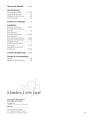
Safety Instructions ........... 2-4
Operating Instructions
Controls ........................... 4-8
Quick Start Guide .................... 5
Using the Dryer ...................... 9
Features ............................ 10
Care and Cleaning ............ 11
Installation Instructions
Before You Begin ............... 12- 14
Connecting the inlet Hoses ......... 15
Connecting a Gas Dryer ......... 16-19
Connecting an
Electric Dryer .................... 20-22
Exhausting the Dryer ............ 23-29
Final Setup .......................... 30
Reversing the Door Swing ....... 31-34
Stacking the Washer
and Dryer ....................... 36-38
Troubleshooting Tips....... 39-42
Consumer Support
Consumer Support ........ Back Cover
Warranty (Canada) ................. 44
Warranty (U.S.)..................... 43
GFDR485
GFDR480
GFDS375
GFDS370
GHDS365
GHDS360
GFDS265
GFDS260
GFDS2££
GFDS2£O
S cheuses
Lo section frangaise commence _ la page 45
Secadoras
_ i _
La secci6n en espaflol empieza en la p6gina 91
Printed inthe United States
Write the model and serial
numbers here:
Model #
Serial #
They are on the label on the front
of the dryer behind the door.
49-90470-./.
06-13 GE

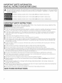
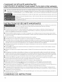
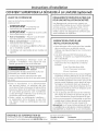
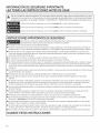
IMPORTANT SAFETY INFORMATION.
READ ALL INSTRUCTIONS BEFORE USING.
_j_ This isthe safety alert symbol. This symbol alerts to potential hazards that can kill or hurt and others.
you you you
All safety messages will follow the safety alert symbol and the word "DANGER","WARNING" or "CAUTION".These
words are defined as:
_ Indicates a hazardous situation which, if not avoided, will result in death or serious inJury.
Indicates a hazardous situation which, if not avoided, could result in death or serious injury.
Indicates a hazardous situation which, if not avoided, could result in minor or moderate injury.
IMPORTANT SAFETYINSTRUCTIONS
To reduce the riskof fire, explosion,electric shock, or injury to persons when using your appliance,follow
basic precautions, including the following:
[] Readall instructionsbeforeusingtheappliance.
[] DONOTdry articles that have been previously cleaned in,washed in, soaked in or spotted with gasoline, dry-cleaning
solvents, or other flammable or explosive substances, as they give off vapors that could ignite or explode.
[] DONOTallow children to play on or in this appliance. Close supervision of children is necessary when this appliance
is used near children. Before the appliance is removed from service or discarded, remove the door to the drying
compartment.
[] DONOTreach into the appliance if the drum is moving.
[] DONOTinstall or store this appliance where it will be exposed to the weather.
[] DONOTtamper with controls, repair or replace any part of this appliance or attempt any servicing unless specifically
recommended in the user maintenance instructions or in published user repair instructions that you understand and
have the skills to carry out.
[] DONOTuse fabric softeners or products to eliminate static unless recommended by the manufacturer of the fabric
softener or product.
[] DONOTuseheat to dry articles containing foam rubber or similarlytextured rubber-like materials.
[] Clean lint screen before or after each load. DONOToperate the dryer without the lint filter in place.
[] Donot storecombustible materials, gasoline or other flammable liquids near the dryer. Keep area around the exhaust
opening and adjacent surrounding areas free from the accumulation of lint, dust and dirt. Keep dryer area clear and free
from items that would obstruct the flow of combustion and ventilation air.
[] The interior of the appliance and exhaust duct should be cleaned periodically by qualified service personnel.
[] DONOTplace items exposed to cooking oils in your dryer. Items contaminated with cooking oils may contribute to a
chemical reaction that could cause a load to catch fire.
[] Keepthe floor around your appliances clean and dry to reduce the possibility of slipping.
[] Unplugthe appliance orturn off the circuit breaker before servicing. Pressingthe Power or Start/Pause button DOESNOT
disconnect power.
[] DONOToperate this appliance if it isdamaged, malfunctioning, partially disassembled,or has missingor broken parts,
including a damaged cord or plug.
[] DONOTsprayany type of aerosol into, on or near dryer at any time. Donot use anytype of spray cleanerwhen cleaningdryer
interior. Hazardousfumes or electrical shock could occur.
[] See "Electrical Connection" located in the Installation Instructions for grounding instructions.
SAVETHESE INSTRUCTIONS
2

GEAppliances.com
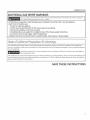
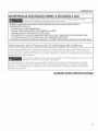
ADDITIONAL GAS DRYERWARNINGS
I Foryour safety,the information in this manual must be followed to minimize the riskof fire or explosion
or to prevent damage, personal injury, or death.
- DONOTstore or usegasolineor other flammable vapors and liquids in the vicinity of this or any other appliance.
- WHATTODOIFYOUSMELLGAS:
• DONOTtry to light any appliance.
• DONOTtouch any electrical switch; DONOTuseany phone in your building.
• Clearthe room, building, or area of any occupants.
• Immediately call your gas supplierfrom a neighboCsphone.Followthe gassupplieCsinstructions.
• Ifyou cannot reachyour gassupplier, call the fire department.
- Installation and service must be performed by a qualified installer, serviceagency,or the gassupplier.
I
State of California Proposition 65 Warnings:
TheCaliforniaSafeDrinkingWater and ToxicEnforcementAct requiresthe governorof Californiato publisha listof substances
known to the stateto cause cancer,birth defects or other reproductive harm and requiresbusinessesto warn of potential exposure
to such substances.
Thisproduct contains one or more chemicals known to the State of Californiato cause cancer,birth defects or
other reproductiveharm.
Gasappliancescan cause low-level exposureto some of these substances,includingbenzene,carbon monoxide,formaldehyde and
soot,causedprimarily by the incomplete combustion of natural gasor LPfuels. Exposureto these substancescan be minimizedby
properlyventing the dryerto the outdoors.
SAVE THESE INSTRUCTIONS

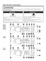
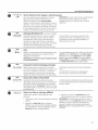
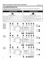
About the dryer control panel.
WARNING!
To reduce the risk of fire, electric shock, or injury to persons, read the IMPORTANTSAFETYINSTRUCTIONSbefore
operating this appliance.
Explosion Hazard
Keepflammable materialsand vapors,such as gasoline,away
from dryer.
DONOTdry anything that hasever had anything flammable on
it(evenafter washing).
Failureto do socan resultin death, explosion,or fire.
Fire Hazard
Nowashercan completely remove oil.
Donot dry anythingthat haseverhad any type of oil on it
(includingcooking oils).
Items containing foam, rubber,or plasticmust be dried on a
clotheslineor by usingan air dry cycle.
Failureto follow these instructionscan result in death or fire.
Throughout this manual, features and appearance may vary Fromyour model.
Delicates
Speed Dry
Start/P_use _
Light
Volume
@-7
0
Hodels:
GFDS255
GFDS250
Normal
l_ii×edLoods Towels/
Cottons 0 Sheets lad Se_ords_ _re
: terns
Bulky
tSedding _ _ Sanitize
Lock_ontrol Active
Wear
Delicates
Speed Dry
x um m r
Estimated T_me R_ma_n ng Hlg_
[ Cycle
Complete More Dry
Dry
Damp
Start/Pause _
0
0
Hodels:
GFDS255
GFDS250
4
Lock"C_.ontrol
S _ems
Bulky
Bedding
Active
Wear Q
Delicates •
Speed Dry t
Normal
MixedLoads Towels/
Q Sheets ,_,_is_,o ,,_,,*s,_ ...................................................................
Sanitize Esm°tdtimeRem_{ning
I _ _ Cycle
Stea-fi(C) I t"l _ _.J ........
O-O O_
Steam Drying_ Damp_ Cool_
Refresh Energy Smart Down
Time _----
Cottonso
............ × m
High
Medium More Dry
LOW Dry
Extra Low Less Dry
NO Heat Damp
StortyPouse _
0
0

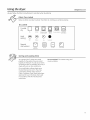
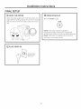
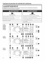
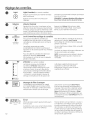
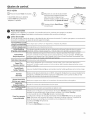
Control settings.
Quick Start
E] Press the Power button.
If the screen isdark, a press
of the Power button will
"wake up" the display.
Power
@
Normal
M_ed to_s Towels!
'_ C°tt°ns t 0 0 SheetsSelecta dry cycle. (Defaultsare set 0,,,y
B_d_J,,_ _ 0 Sanitize
for each cycle.Thesedefault Aoti..... _,_
Wear •
settings can be changed. See
Delicates O __Vpar rn
Control settings for more
information.) spoodOry
Dry
E] Press the Start/Pause button.
Start/Pause
GEAppliances.com
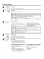
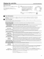
Power
Press to "wake up" the display. Ifthe display is active, press to turn the dryer off.
NOTE: Pressing Power does not disconnect the appliance from the power supply.
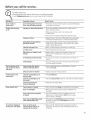
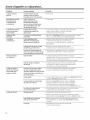
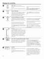
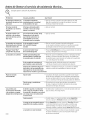
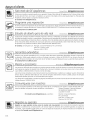
Dry Cycles
The dry cycle controls the length and tumble speed of the drying process. The chart below will help you match the dry
setting with the loads.
Normal/Mixed Loads Forloads consisting of cottons and poly-blends.
Cottons Forcottons and most linens.
Forlargecoats, bed spreads,mattress covers,sleeping bags, blankets,comforters,jackets, small
Bulky/Bedding rugs,and similar large and bulky items.
Clothing worn for active sports exerciseand some casual wear. Fabricsincludenew technology
Active Wear finishes and stretch fibers such as Spandex.Alsofor clothing labeled EasyCureor Perma Press:
Forwrinkle-free and permanent press items.
Delicates Forlingerieand special-carefabrics.
Speed Dry Forsmallloads that are needed in a hurry, such assports or school uniforms. Canalso be used if
the previous cycle left some items damp, such as collars or waistbands.
Towels/Sheets Usefor towels ORsheets. It is not recommended to mix towels and sheets in the same load.
Reducescertain types of bacteria by 99.8%,including: Staphylococcus aureus, Pseudomonas
Sanitize aeruginosa, and Klebsiellapneumoniae. Theantibacterial processoccurs when high heat is used
during a portion of this drying cycle.
Steam Dewrinkle
Idealfor loads leftin dryer for an extended time.
Full Loads
Warm Up Provides10 minutes of warming time to warm up clothes.
Air Fluff
Time Dry
Useto tumble items without heat.
Useto set your own dry time. Time Dry isalso recommended for small loads.To use:
!. Turn dry cycle dial to Time Dry.
2. Increase the drying time by pressing the Add Time button.
Note: This button only increases the time. When max time is reached, pressing the button
again will reset the counter to the lowest setting.
5. Select the Temp.
4. Close the door.
5. PressStart/Pause.

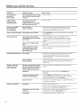
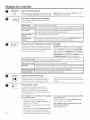
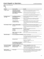
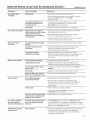
Control settings.
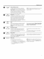
Add Time
®1
Add Time
Press to add time to the Steam Dewrinkle,
Warm Up, Air Fluff or Time Dry cycles.
[
Temp I
Dry Tamp
You can change the temperature of your dry
cycle.
High For regular to heavy cottons.
Medium Forsynthetics, blends and items labeled Permanent Press.
Low Fordelicates, synthetics and items labeled Tumble Dry Low.
Extra Low For lingerie and special-care fabrics.
No Heat This option may only be used with Air Fluff, in which items are tumbled without
heat.
!
Level
)
Sensor Dry Level
Thesensorcontinuously monitors the amount of
moisture in the load.When the moisture inyour
clothes reaches your selected dry level,the dryer
will stop.
NOTE:Sensor dry Level only works with
Cottons, Normal, Active Wear, Delicates,
Speed Dry, Bulky, Towels/Sheets, Sanitize
and Steam Dewrinkle cycles.
Extra Dry Usefor heavy-duty fabrics or items that should be very dry,such astowels.
Ion some models)
More Dry Usefor heavy or mixed type offabrics.
Dry Usefor normal drynesslevelsuitable for most loads.This isthe preferred cycle for
energy saving.
Less Dry Use for lighter fabric (ideal for ironing).
Damp Forleaving items partially damp.
Start/Pause
My Cycle
--/
Iold 3 Second5 to Store
Start/Pause
Press to start a dry cycle. If the dryer is
running, press it once and it will pause the
dryer. Press it again to resume the dry cycle.
Ny Cycle
Set up your favorite combination of settings
and save them here for one touch recall.
These custom settings can be set while a cycle
is in progress.
To store a Ny Cycle combination of settings:
1. Select your drying cycle.
2. Change Temp and Level settings to fit your
needs.
3. Select any drying options you want.
4. Pressand hold the NV Cycle button for 3
seconds to store your selection. A beep will
sound and the button will light up.
To recall your stored Ny Cycle combination:
Press the NY CYCLEbutton before drying a
load.
To change your stored Ny Cycle
combination:
Repeat steps 1-4.
6

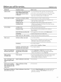
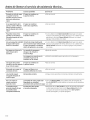
GEAppliances.com
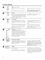
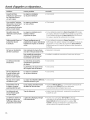
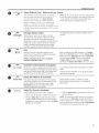
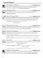
Steam Refresh ,_
_-5terns
Steam Refresh Cycle
For slightly wrinkled dry garments. Significantly
reduces wrinkles on up to 5 garments. After the
Steam Refresh Cycle, the unit will beep and display
"0:00." Ifthe unit is not turned off or ifthe door is
not opened, the dryer willcontinue to tumble for
30 minutes. At the end of 30 minutes, itwill display
"0:00" and the cycle will be complete.
NOTE'.A singleextremely light fabric item may need
to have an additional item included to achieve
optimum results.
Detangle (on some models)
Activates reverse tumbling to reduce tangling, dry
more evenly,and improve drying times. Typical
loadssuch as bed and bath mixed loads,where
sheets,towels and pillow casesare laundered
together, benefit from this capability. When the
dryer reversesdirection, there will be a slight pause
and sound change. This isnormal.
eDry
e Dry Reducesthe total energy consumption of specific
dryer cycles byadjusting certain heat settings.
NOTE: Cycle times will change when e-Dry is
selected.
Thiscyclecan be usedwith Cottons, Normal, Active
Wear, Delicates, Speed Dry, Bulky, Towels-Sheets,
Sanitize and Steam Dewrinkle.
Damp Alert
Delay Dry
Extended Tumble
Minimizeswrinkles by adding approximately 60
minutes of no-heat tumbling after clothes are
dry. Thebeeperwill sound every five minutes as a
reminder to remove the clothes.
Theestimated time remaining display will show
"0:00".
Theextendedtumble time does not get added to
the cycletime onthe display.
Damp Alert
Thisoption causesthe dryer to beepwhen clothes
have dried to a damp level.Removeitems that you
wish to hang dry. TheDamp Alert will only beep
when this option is selected.
Removingclothes and hanging them when they are
damp can reduce the need to iron some items.
Delay Dry
Useto delay the start of your dryer.
1. Chooseyour dry cycle and any options.
2. PressDelay Dry. Youcan change the delay time
in I hour increments, using the Delay Dry button.
3. Pressthe Start/Pause button to start the
countdown.
NOTE:Ifthe door is opened while the dryer is in
Delay Dry, the countdown time will not restart
unless the door is closed and Start/Pause button
has been pressed again.

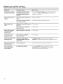
Control settings.
Light
@
Light (on some models)
Press the button to turn on the light in the
dryer.
Press the button again to turn the light off.
This only controls the light when the door is
shut.
NOTE: The light will turn off by itself after
one minute when the door is shut.
Volume
Volume
Alertsyou that the cycleis complete. Thebeeper
will continue to sound every minute for the next
5 minutes, until the clothes have been removed.
Theclothes should beremoved when the beeper
goes off sowrinkles don't set in.
PressVolume to select low, medium or high
volume, or to turn the beeper off.
B
LockControl
®
Hold 3Secsto
Lock / Unlock
Lock Control
You can lock the controls to prevent any
selections from being made. Or you can lock
or unlock the controls after you have started
u cycle.
Children cannot accidentally start the dryer by
touching buttons with this option selected.
To lock the dryer, press and hold the Lock
Control button for 3 seconds.
To unlock the dryer controls, press and hold
the Lock Control button for 3 seconds.
A sound is made to indicate the lock/unlock
status.
The indicator light above the button will
illuminate when the controls are locked.
NOTE:The Power button can still be used
when the machine is locked.
e Monitor
g
eMonitor (on some models)
The eMonitor lights display the relative
energy use of your selected cycle and options.
They are provided as an energy guide and
range from Good (1 light) to Better (5 lights).
Cycle (time), dryness level, temperature, and
additional tumble options can increase or
decrease your energy efficiency. Some cycles
will not provide a display.
Clean i
Filter
Clean Filter Message
Thismessage representsonly a reminder and
does not always appear when the filter needs
cleaning.The filter should be cleaned offer every
drying cycleiscomplete.
Thismessagewill disappear after the Start/
Pause button is pressed.Eventhough you may
have already cleaned the filter (beforeor after
the Power button has been pressed),the "Clean
Filter" messagewill still be displayed until the
Start/Pause button isactivated.
!D'O n Cyc'°
Complete
121.0 0 oo ooo,o.
Steam Drying_ Demp_ Cool_
Refresh Down
Energy Smart
Display
Displays the approximate time remaining until
the end of the cycle.
Asthe cycle begins, you will see an initial
approximate total cycle time in the display.
Then lights will "race" in the display. This
means the dryer is continuously monitoring
the amount of moisture in the load. The lights
will continue until the dryer senses a low level
of moisture in the load. At that point, the dryer
will calculate and display the approximate
time remaining.

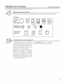
Using the dryer. GEAppliances.com
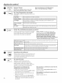
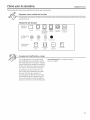
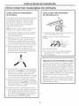
Always follow the fabric manufacturer's care label when laundering.
Fabric Care Labels
Below are fabric care label "symbols" that affect the clothing you willbe laundering.
Dry Labels
--'1 DO not dry
Dry Normal Permanent Press/ Gentle/ Do not tumble dry (used with
wrinkle resistant delicate do not wash)
setting
High Medium Low No heat/air
_Psetcialtions El r_ E_
Line dry/ Drip dry Dry fiat In the shade
hang to dry
Sorting and Loading Hints
Asageneral rule, ifclothes are sorted
properly for the washer,they are sorted
properly for the dryer.Try also to sort items
according to size.Forexample, donot dry a
sheet with socksor other small items.
Do not add fabric softener sheets once
the load has become warm. They may
cause fabric softener stains.Bounce®
Fabric Conditioner Dryer Sheetshave been
approved for use in this dryer when used
in accordance with the manufacturer's
instructions.
Do not overload. Thiswastes energy and
causeswrinkling.

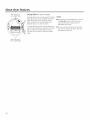
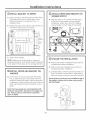
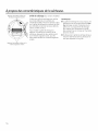
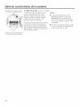
About dryer features.
Rest rear legs on
rear angled ledge
Drying Rack (onsome models)
A handy drying rack may be used for drying
delicate items such as washable sweaters.
Place items flat on the drying rack and
block such items as wool sweaters and
delicate fabrics. Dry with low heat.
To install the drying rack, extend the drying
rack into the dryer drum. Rest the front two
legs on the front angled ledge and then
rest the rear two legs on the rear angled
edge.
NOTES:
[] The drying rack is designed for use with
the Time OrV cycles. Use with sensor
cycles may result in damp items or
extended cycle times.
[] Do not use this drying rack when there
are other clothes in the dryer, that are
not placed on the rack.
Restfront legs on
front angled ledge
10

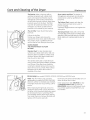
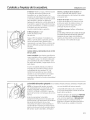
Care and Cleaning of the Dryer. GEAppliances.com
The Exterion Wipe or dust any spills or
washing compounds with a dump cloth.
Dryer control panel and finishes may be
damaged by some laundry pretreatment
soil and stain remover products. Apply these
products away from the dryer. The fabric
may then be washed and dried normally.
Damage to your dryer caused by these
products is not covered byyour warranty.
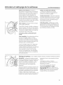
The Lint Filter'. Cleanthe lint filter before
each use.
Pull out the lint filter.
Moisten your fingers and remove the
captured lint. Once clean, slide the filter back
into position. Have a qualified technician
vacuum the lint from the dryer once a year.
NEVER OPERATE
THE DRYER WITHOUT ITS FILTER
IN PLACE.
Stainless Steel: To clean stainless steel
surfaces usea damp cloth with a mild, non-
abrasive cleaner suitable for stainless steel
surfaces. Removethe cleaner residue and
then dry with a clean cloth.
Thestainless steel used to make the dryer
drum provides the highest reliability available
in a GEdryer. If the dryer drum should be
scratched or dented during normal use, the
drum will not rust or corrode. These surface
blemishes will not affect the function or
durability of the drum.
Drver Interior and Duct: The interior of
the appliance and exhaust duct should be
cleaned once a year by qualified service
personnel.
TheExhaust Duct: Inspect and clean the
exhaust ducting at least once a year to
prevent clogging.
A partially clogged exhaust can lengthen the
drying time.
TheExhaust Hood: Checkwith o mirror that
the insideflops of the hood move freely when
operating. Make surethat there is no wildlife
(birds,insects,etc.)nesting insidethe duct or
hood.
Drum Lump (on models GFDS250, GFDS255, GFDS260 and GFDS265 only)
NOTE:The drum lamp is not consumer
replaceable on models GHDS360, GHDS365,
GFDS370,GFDS375,GFDR480and GFDR485.
If this light should ever stop working, call for
service.
Before replacing the light bulb, be sure to
unplug the dryer power cord or disconnect
the dryer at the household distribution panel
by removing the fuse or switching off the
circuit breaker. Reach above dryer opening
from inside the drum. Remove the bulb and
Drum lamp only (and automatically) turns on
when the dryer door is open.
Order replacement bulb WE4M305 on-line
at GEApplianceParts.com, by phone at
800.626.2002 during normal business hours,
or purchase appliance bulb 7C7from your
local retailer.
replace with the same size bulb.
11

Installati
Instructi
n
ns
Dryers
Questions? Call 800.GE.CARES (800.432.2737) or visit our Web site at: GEAppliances.com
In Canada, call 1.800.561.3344 or visit www.GEAppliances.ca
_4_ Thisisthe safety alert symbol.Thissymbol alertsyou to potential hazardsthat can killyou or hurt you and others.
Allsafety messageswill follow the safety alert symbol and the word "DANGER","WARNING",or"CAUTION".These
words are defined as:
Indicates a hazardous situation which, if not avoided, will result in death or serious injury.
Indicates a hazardous situation which, if not avoidec could result in death or serious injury.
_ Indicates a hazardous situation which, if not avoidec could result in minor or moderate inJury.
BEFORE YOU BEGIN
Readthese instructions completely and carefully.
• IMPORTANT- Savethese instructions for local
electrical inspector's use.
• IMPORTANT- Observe all governing codes and
ordinances.
• Installthe clothes dryer according to the manufacturer's
instructions and local codes.
• Note to Installer - Be sure to leave these instructions
with the Consumer.
• Note to Consumer - Keepthese instructions for future
reference.
• Clothes dryer installation must be performed by a
qualified installer.
• Thisdryer must be exhausted to the outdoors.
, Beforethe old dryer is removed from service or
discarded, remove the dryer door.
, Service information and the wiring diagram are located
in the control console.
, Donot allow children on or in the appliance. Close
supervision of children is necessary when the appliance
isused near children.
, Proper installation isthe responsibility of the installer.
, Product failure due to improper installation isnot
covered under the Warranty.
• Install the dryer where the temperature is above 50°F
for satisfactory operation of the dryer control system.
, Remove and discard existing plastic or metal foil duct
and replace with UL-listed duct.
- Fire Hazard
• Clothes dryer installation must be performed by a
qualified installer.
• Install the clothes dryer according to these
instructions and local codes.
DO NOT install a clothes dryer with flexible plastic
venting materials. If flexible metal (semi-rigid or
foil-type) duct is installed, it must be UL-listed and
installed in accordance with the instructions found
in "Connecting the Dryer to House Vent" later in
this manual. Flexible vent materials are known to
collapse, be easily crushed and trap lint. These
conditions will obstruct dryer airflow and increase
the risk of fire.
DO NOT install or store this appliance in any
location where it could be exposed to water or
weather.
To reduce the risk of severe injury or death, follow
all installation instructions.
Save these instructions. (Installers: Be sure to leave
these instructions with the customer.)
12

Installation Instructions
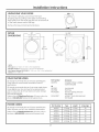
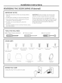
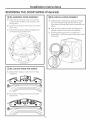
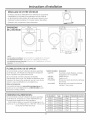
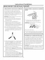
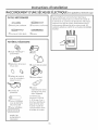
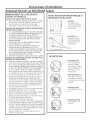
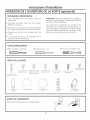
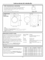
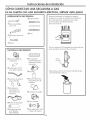
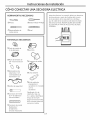
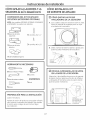
UNPACKING YOUR DRYER
Tilt the dryer sideways and remove the foam
shipping pads by pulling at the sides and breaking
them away from the dryer legs. Be sure to remove all
of the foam pieces around the legs.
Remove the bag containing the literature.
DRYER 28" 54s/8"
DIMENSIONS (71.12cm) __ (ZSB.1cm)
©
s2 7/8"
Front View -- (83.5 cm) --
*NOTE:
With Legs: 40 1/2" (102.5 cm) - (5/4" (1.9 cm) adjustability)
With Built-In RiserTM: 46" (116.9 cm) - (3/4" (1,9 cm) adjustability)
With Optional Pedestal {GF×P1308): 52" (132.1 cm) - (3/4" (1.9 cm) adjustability)
Stacked: 78 1/4" (198.8 cm)
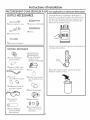
STEAM WATER HOSES:
GEstrongly recommends the useof factory specifiedparts.
Thesehoses are manufactured and tested to meet GE
specifications.
GEstrongly recommends the useof new water supply hoses.
Hosesdegrade overtime and need to be replaced every 5
years to reducethe riskof hosefailures and water damage.
Parts and Accessories
Order on-line at GEApplianceParts.com, 24 hours a day or by
phone at 800.626.2002during normal businesshours.
Part Number
WE25M53
OR
WE1M847
WE1M848
PM14X10056
WX14X10007
Accessory
CompleteKit(hoses,Y-adapter
washers)(included)
LongHoseand
ShortHose
Dryerdooropeningventbrush
(notincluded)
LintEaterTM Dryerrotarytubebrush
(notincluded)
POWER CORDS:
GEstrongly recommends the useof factory specified parts.
Selectthe power cord to fit your installation requirements.
Order on-line at GEApplianceParts.com, 24 hours a day or
by phone at 800.626.2002during normal businesshours.
Part Number Type Length L Amperage
WX9X2 :3-Prong 4 Feet 30
WX9X3 3-Prong 5 Feet 30
WX9X4 :3-Prong 6 Feet 30
WX9X18 4-Prong 4 Feet 30
WX9X19 _ 4-Prong • 5 Feet . 30
WX9X20 4-Prong 6 Feet 30
13

Instollotion Instructions
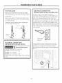
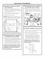
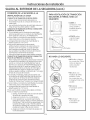
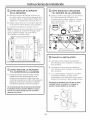
REQUIREMENTS FOR ALCOVE OR
CLOSET INSTALLATION
_- Explosion Hazard
Keepflammable materialsand vapors,suchasgasoline,
awayfrom dryer.
Placedryerat least18"(46cm)abovethe floorfor a
garageinstallation.
Failureto dosocan resultin death,explosion,orfire.
, If the dryer is approved for installation in an
alcove or closet, it will be stated on a label on the
dryer back.
, The dryer MUST be vented to the outdoors.
, Minimum clearance between dryer cabinet and
adjacent walls or other surfaces is:
0" either side
3" front
3" rear
l" top
52" from floor to overhead cabinets
Consideration must be given to provide adequate
clearance for installation and service.
, Closet ventilation openings required: 2 louvers
each 60 square inches (387 square cm), located 3
inches (7.6 cm) from top and bottom of door.
Gas Dryers Only:
, No other fuel burning appliance shall be installed
in the same closet as a gas dryer.
, The dryer must be disconnected from the gas
supply piping during pressure testing at pressures
greater than 1,_psi (3.5 kPa).
, A 1/8 inch NPT minimum plugged tapping,
accessible for test gauge connection, must be
installed immediately upstream of the gas supply
connection to the dryer.
MOBILE OR MANUFACTURED HOME
INSTALLATION
,, Installation must conform to the
MANUFACTURED HOME CONSTRUCTION AND
SAFETYSTANDARD, TITLE 24, PART32-80 or
Standard CAN/CSA-Z240 MH, or, when such
standard is not applicable, with AMERICAN
NATIONAL STANDARD FOR MOBILE HOME,
ANSI/NFPA NO. 50lB.
, The dryer MUST be vented to the outdoors. The
exhaust vent must be securely fastened to a
non-combustible portion of the mobile home.
,, The vent MUST NOT be terminated beneath a
mobile or manufactured home.
, The vent duct material MUST BE METAL.
,, KIT 14-D346-33 MUST be used to attach the dryer
securely to the structure.
, The vent MUST NOT be connected to any other
duct, vent or chimney.
, Do not use sheet metal screws or other
fastening devices which extend into the interior
of the exhaust vent.
, Provide an opening with a free area of at least
25 square inches for introduction of outside air
into the dryer room.
, See the sections for electrical connection
information.
14

Installation Instructions
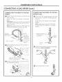
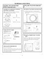
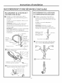
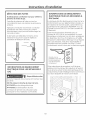
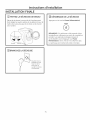
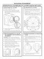
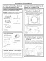
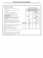
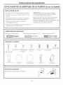
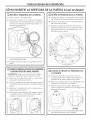
CONNECTING INLET HOSES
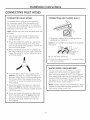
CONNECTING INLET HOSES
To produce steam, the dryer must connect to
the cold water supply. Since the washer must
also connect to the cold water, a "Y" connector
is inserted to allow both inlet hoses to make that
connection at the same time.
NOTE: Use the new inlet hoses provided; never use
old hoses.
. Turn the cold water faucet off. Remove the
washer inlet hose from the washer fill valve
connector (cold).
2. Ensure the rubber flat washer is in place and
screw the female coupling of the short hose
onto the washer fill valve connector. Tighten by
hand until firmly seated.
3. Attach the female end of the "Y" connector to
the male coupling of the short hose. Ensure the
rubber flat washer is in place. Tighten by hand
until firmly seated.
4. Insert the filter screen in the coupling of the
washer's inlet hose. If a rubber flat washer is
already in place remove it before installing the
filter screen. Attach this coupling to one male
end of the "Y" connector. Tighten by hand until
firmly seated.
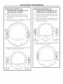
5. Ensure the rubber flat washer is in place and
attach the dryer's long inlet hose to the other
male end of the "Y" connector. Tighten by hand
until firmly seated.
.
Ensure the rubber flat washer is in place and
attach the other end of the dryer's long inlet
hose to the fill valve connector at the top of
the dryer back panel. Tighten by hand until
firmly seated.
CONNECTING INLET HOSES (cont.)
7. Using pliers, tighten all the couplings with an
additional two-thirds turn.
NOTE: Do not overtighten. Damage to the couplings
may result.
8. Turn the water faucet on.
9. Check for leaks around the "Y" connector, faucet
and hose couplings.
WATER SUPPLY REgUIREMENTS
Hot and cold water faucets MUST be installed
within 42 in. (107 cm) of your washer's water
inlet. The faucets MUST be 3/4 in. (1.9 cm) garden
hose-type so inlet hoses can be connected. Water
pressure MUST be between 10 and 120 pounds
per square inch. Your water department can
advise you of your water pressure.
NOTE: A water softener is recommended to reduce
buildup of scale inside the steam generator if the
home water supply is very hard.
15

Installation Instructions
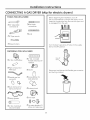
CONNECTING A GAS
TOOLS YOU WILL NEED
DRYER(ski
17lO" Adjustable
wrenches (2)
178" Pipe wrench
0 Flat-blade
screwdriver
13Level
17Slip-joint pliers
MATERIALS YOU WILL NEED
04" dia. metal elbow
OPipe compound or
PTFEtape
17Flexible gas line
connector
%
174" dia., UL-listed
flexible metal duct (if
needed)
17Gloves
0
C1Soap solution for
leak detection
17Duct clamps (2) or
Spring clamps (2)
1:3Safety glasses
}
04" dia. metal duct
(recommended)
13Exhaust hood
17Duct tape
OGas pipe adapters (2),
elbow and pipe plug
) for electric dryers)
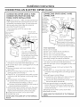
Before beginning the installation, turn off
the circuit breaker(s) or remove the dryer's circuit
fuse(s) at the electrical box. Be sure the dryer cord
is unplugged from the wall.
Turn the dryer's gas shut-off valve in the supply
line to the OFF position.
Shut-off
Valve
Disconnect and discard old flexible gas connector
and ducting material.
16

Installation Instructions
GAS REQUIREMENTS
o
o
o
_'- Explosion Hazard
Use a new CSAInternational approved flexible
gas supply line. Never reuse old flexible
connectors.
Install a shut-off valve.
Securely tighten all gas connections.
If connected to LP gas, have a qualified person
make sure gas pressure does not exceed 13"
water column.
. Examples of a qualified person include: licensed
heating personnel, authorized gas company
personnel, and authorized service personnel.
. Failure to do so can result in death, explosion,
or fire.
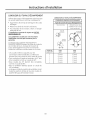
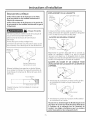
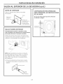
DRYER GAS SUPPLY CONNECTION
i i%2"
(4.05 cm)
t 3/8" NPT MALE THREAD GAS SUPPLY
47/ld ' (11.27 cm)
NOTE: Add to vertical dimension
the distance between cabinet
bottom to floor.
You must use with this dryer a flexible metal
connector (listed connector ANSI Z21.24 / CSA 6i0).
The length of the connect shall not exceed 3 ft.
GAS SUPPLY
, A 1/8" National Pipe Taper thread plugged
tapping, accessible for test gauge connection,
must be installed immediately upstream of the
gas supply connection to the dryer. Contact
your local gas utility should you have questions
on the installation of the plugged tapping.
, Supply line is to be 1/2" rigid pipe and equipped
with an accessible shutoff within 6 feet of, and
in the same room with, the dryer.
, Use pipe thread compound appropriate for
natural or LP gas or use PTFEtape.
, Connect flexible metal connector to dryer and
gas supply.
The installation must conform with local codes,
or in the absence of local codes, with the
National Fuel Gas Code, ANSI Z223.1/NFPA 54,
or the Natural Gas and Propane Installation
Code, CSA B149i.
IN THE COMMONWEALTH OF
MASSACHUSETTS
. This product must be installed by a licensed
plumber or gas fitter.
. When using ball-type gas shut-off valves, they
shall be the T-handle type.
. A flexible gas connector, when used, must not
exceed 3 feet.
ADJUSTING FOR ELEVATION
Gas clothes dryers input ratings are based on
sea level operation and need not be adjusted
for operation at or below 2000 ft. elevation. For
operation at elevations above 2000 ft., input
ratings should be reduced at a rate of 4 percent
for each 1000 ft. above sea level.
Installation must conform to local codes and
ordinances or, in their absence, the NATIONAL
FUEL GAS CODE, ANSI Z223.
17

Installation Instructions
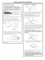
CONNECTING A GAS DRYER (cont,)
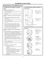
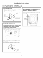
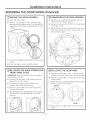
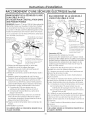
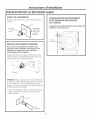
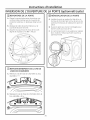
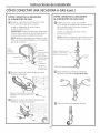
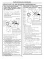
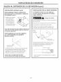
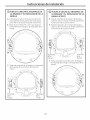
CONNECTING THE DRYER TO THE GAS
SUPPLY
@
Install a female 3/8" NPT elbow at the end of the
dryer gas inlet.
Install a 3/8" flare union adapter to the female
elbow.
IMPORTANT: Use a pipe wrench to securely hold
on to the end of the dryer gas inlet to prevent
twisting the inlet.
NOTE: Apply pipe compound or PTFEtape to the
threads of the adapter and dryer gas inlet.
New Metal
Flexible Gas
Line Connector
Ada
Items not supplied
]/8" NPT
Adapter
!/8" NPT
Pipe Plug for
Checking Gas
Inlet Pressure
Shut-Off Valve
Pipe size at
least 1/2"
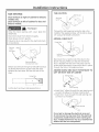
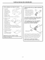
rB1 Attach the flexible metal gas line connector to
the adapter.
Apply pipe compound
adapter and dryer gas inlet.
rc1 Tighten the flexible gas line connection, using
two adjustable wrenches.
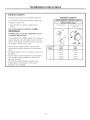
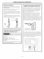
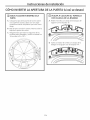
CONNECTING THE DRYERTO THE GAS
SUPPLY(cont.)
@Install a 1/8" NPT plugged tapping to the dryer
gas line shut-off valve for checking gas inlet
pressure.
Install a flare union adapter to the plugged
tapping.
NOTE: Apply pipe compound or PTFEtape
to the threads of the adapter and plugged
tapping.
Apply pipe compound
or PTFEtape to all
male threads.
Shut-Off
Valve
Plugged
r_ Tighten all connections, using two adjustable
wrenches. Do not overtighten.
[] Open the gas shut-off valve.
18

Installation Instructions
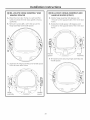
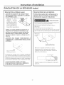
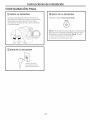
TEST FOR LEAKS
Never use an open flame to test for gas leaks.
Check all connections for leaks with soapy solution
or equivalent.
Apply a soap solution. The leak test solution must
not contain ammonia, which could cause damage
to the brass fittings.
If leaks are found, close the valve, retighten the
joint and repeat the soap test.
Open Gas
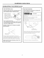
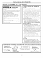
ELECTRICAL CONNECTION
INFORMATION FOR GAS DRYERS
_ - Electrical Shock Hazard
Plug into a grounded 3 prong outlet.
DO NOT remove ground prong.
DO NOT use an adapter.
DO NOT use an extension cord.
Failure to do so can result in death, fire or electrical
shock.
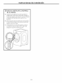
ELECTRICAL CONNECTION
INFORMATION FOR GAS DRYERS (cont.}
The dryer must be electrically grounded in
accordance with local codes, or in the absence of
local codes, with the National Electrical Code, ANSI/
NFPA 70 or Canadian Electrical Code, CSA C22.1
This appliance must be supplied with 120V, 60Hz, and
be connected to a properly grounded branch circuit
protected by a 15 or 20 amp circuit breaker or time
delay fuse. If electrical supply provided does not meet
these requirements, it is the owner's responsibility to
have a licensed electrician install a properly grounded
3-prong outlet.
Ensure proper
ground exists
before use.
If local codes permit an external ground wire (not
provided) may be added by attaching to the green
ground screw on the rear of the dryer, and to a
grounded metal cold water pipe or other established
ground.
Ground
Screw
19

Installation Instructions
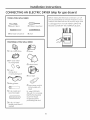
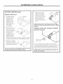
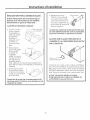
CONNECTING AN ELECTRIC DRYER(skip for gas dryersl
TOOLS YOU WILL NEED
17Slip-joint pliers
17Flat-blade crewdriver
17Phillips screwdriver
17Level
MATERIALS YOU WILL NEED
17Gloves
173/4" strain relief
(UL recognized)
%
04" duct
clamps (2) or
4" spring clamps (2)
0 Safety glasses
04" dia. metal duct
(recommended)
174" dia., UL-listed
flexible metal duct (if
needed)
0 Exhaust hood
17Duct tape
17Dryer power cord kit
(not provided with
dryer)
UL rated 120/240V,
30A with 3 or 4 prongs.
Identify the plug type
as per the house
receptacle before
purchasing line cord.
Before making the electrical connection, turn off
the circuit breaker(s) or remove the dryer's circuit
fuse(s) at the electrical box. Be sure the dryer cord
is unplugged from the wall. NEVER LEAVE THE
ACCESS COVER OFF THE TERMINAL BLOCK.
20
La page est en cours de chargement...
La page est en cours de chargement...
La page est en cours de chargement...
La page est en cours de chargement...
La page est en cours de chargement...
La page est en cours de chargement...
La page est en cours de chargement...
La page est en cours de chargement...
La page est en cours de chargement...
La page est en cours de chargement...
La page est en cours de chargement...
La page est en cours de chargement...
La page est en cours de chargement...
La page est en cours de chargement...
La page est en cours de chargement...
La page est en cours de chargement...
La page est en cours de chargement...
La page est en cours de chargement...
La page est en cours de chargement...
La page est en cours de chargement...
La page est en cours de chargement...
La page est en cours de chargement...
La page est en cours de chargement...
La page est en cours de chargement...
La page est en cours de chargement...
La page est en cours de chargement...
La page est en cours de chargement...
La page est en cours de chargement...
La page est en cours de chargement...
La page est en cours de chargement...
La page est en cours de chargement...
La page est en cours de chargement...
La page est en cours de chargement...
La page est en cours de chargement...
La page est en cours de chargement...
La page est en cours de chargement...
La page est en cours de chargement...
La page est en cours de chargement...
La page est en cours de chargement...
La page est en cours de chargement...
La page est en cours de chargement...
La page est en cours de chargement...
La page est en cours de chargement...
La page est en cours de chargement...
La page est en cours de chargement...
La page est en cours de chargement...
La page est en cours de chargement...
La page est en cours de chargement...
La page est en cours de chargement...
La page est en cours de chargement...
La page est en cours de chargement...
La page est en cours de chargement...
La page est en cours de chargement...
La page est en cours de chargement...
La page est en cours de chargement...
La page est en cours de chargement...
La page est en cours de chargement...
La page est en cours de chargement...
La page est en cours de chargement...
La page est en cours de chargement...
La page est en cours de chargement...
La page est en cours de chargement...
La page est en cours de chargement...
La page est en cours de chargement...
La page est en cours de chargement...
La page est en cours de chargement...
La page est en cours de chargement...
La page est en cours de chargement...
La page est en cours de chargement...
La page est en cours de chargement...
La page est en cours de chargement...
La page est en cours de chargement...
La page est en cours de chargement...
La page est en cours de chargement...
La page est en cours de chargement...
La page est en cours de chargement...
La page est en cours de chargement...
La page est en cours de chargement...
La page est en cours de chargement...
La page est en cours de chargement...
La page est en cours de chargement...
La page est en cours de chargement...
La page est en cours de chargement...
La page est en cours de chargement...
La page est en cours de chargement...
La page est en cours de chargement...
La page est en cours de chargement...
La page est en cours de chargement...
La page est en cours de chargement...
La page est en cours de chargement...
La page est en cours de chargement...
La page est en cours de chargement...
La page est en cours de chargement...
La page est en cours de chargement...
La page est en cours de chargement...
La page est en cours de chargement...
La page est en cours de chargement...
La page est en cours de chargement...
La page est en cours de chargement...
La page est en cours de chargement...
La page est en cours de chargement...
La page est en cours de chargement...
La page est en cours de chargement...
La page est en cours de chargement...
La page est en cours de chargement...
La page est en cours de chargement...
La page est en cours de chargement...
La page est en cours de chargement...
La page est en cours de chargement...
La page est en cours de chargement...
La page est en cours de chargement...
La page est en cours de chargement...
La page est en cours de chargement...
La page est en cours de chargement...
La page est en cours de chargement...
La page est en cours de chargement...
La page est en cours de chargement...
La page est en cours de chargement...
La page est en cours de chargement...
La page est en cours de chargement...
La page est en cours de chargement...
La page est en cours de chargement...
La page est en cours de chargement...
La page est en cours de chargement...
-
 1
1
-
 2
2
-
 3
3
-
 4
4
-
 5
5
-
 6
6
-
 7
7
-
 8
8
-
 9
9
-
 10
10
-
 11
11
-
 12
12
-
 13
13
-
 14
14
-
 15
15
-
 16
16
-
 17
17
-
 18
18
-
 19
19
-
 20
20
-
 21
21
-
 22
22
-
 23
23
-
 24
24
-
 25
25
-
 26
26
-
 27
27
-
 28
28
-
 29
29
-
 30
30
-
 31
31
-
 32
32
-
 33
33
-
 34
34
-
 35
35
-
 36
36
-
 37
37
-
 38
38
-
 39
39
-
 40
40
-
 41
41
-
 42
42
-
 43
43
-
 44
44
-
 45
45
-
 46
46
-
 47
47
-
 48
48
-
 49
49
-
 50
50
-
 51
51
-
 52
52
-
 53
53
-
 54
54
-
 55
55
-
 56
56
-
 57
57
-
 58
58
-
 59
59
-
 60
60
-
 61
61
-
 62
62
-
 63
63
-
 64
64
-
 65
65
-
 66
66
-
 67
67
-
 68
68
-
 69
69
-
 70
70
-
 71
71
-
 72
72
-
 73
73
-
 74
74
-
 75
75
-
 76
76
-
 77
77
-
 78
78
-
 79
79
-
 80
80
-
 81
81
-
 82
82
-
 83
83
-
 84
84
-
 85
85
-
 86
86
-
 87
87
-
 88
88
-
 89
89
-
 90
90
-
 91
91
-
 92
92
-
 93
93
-
 94
94
-
 95
95
-
 96
96
-
 97
97
-
 98
98
-
 99
99
-
 100
100
-
 101
101
-
 102
102
-
 103
103
-
 104
104
-
 105
105
-
 106
106
-
 107
107
-
 108
108
-
 109
109
-
 110
110
-
 111
111
-
 112
112
-
 113
113
-
 114
114
-
 115
115
-
 116
116
-
 117
117
-
 118
118
-
 119
119
-
 120
120
-
 121
121
-
 122
122
-
 123
123
-
 124
124
-
 125
125
-
 126
126
-
 127
127
-
 128
128
-
 129
129
-
 130
130
-
 131
131
-
 132
132
-
 133
133
-
 134
134
-
 135
135
-
 136
136
-
 137
137
-
 138
138
-
 139
139
-
 140
140
-
 141
141
-
 142
142
-
 143
143
-
 144
144


GE GHDS365GF0MC Le manuel du propriétaire
- Taper
- Le manuel du propriétaire
- Ce manuel convient également à
dans d''autres langues
- English: GE GHDS365GF0MC Owner's manual
- español: GE GHDS365GF0MC El manual del propietario