
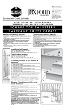
Premier Railing & Stair Kit
BOM-34107816
Read all instructions prior to installing product.
Refer to manufacturers safety instructions when operating any tools.
To register your product, please visit:
barretteoutdoorliving.com
INSTALLATION INSTRUCTIONS
INSTALLATION INSTRUCTIONS
• English
• English
............................................................................................
1
• Français
• Français
• Français
........................................................................................
14
• Español
• Español
• Español
.........................................................................................
27

2
Tape Measure
Level
Hacksaw or Chopsaw
Rubber Mallet
Drill
#2 Square Drive Bit
1
⁄
1
⁄
1
8
⁄8⁄
" Drill Bit
Pencil
Temporary Deck Board
Safety Glasses
TOOLS NEEDED:
WARNING:
• Improper installation of this product can result in personal injury. Always wear safety goggles when
cutting, drilling and assembling the product.
• Incorrect installation may cause harm to the product or individual.
NOTICE:
• DO NOT attempt to assemble the kit if parts are missing or damaged.
• DO NOT return the product to the store. For assistance or replacement parts call: 1-800-336-2383.
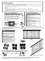
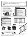
Description
Top Rail
Bottom Rail
Balusters/Spindles
Support Brace(s)
Level Brackets
Stair Brackets
Left-Right Angle Brackets*
1
1
⁄
1
⁄
1
4
⁄4⁄
" Square Drive Screws
2" Square Drive Screws
1" Square Drive Screws
Base Trim*
Templates
Adhesive Foam Strips
Railing & Stair Railing
Components:
*Sold separately.
BEFORE YOU BEGIN:
Top Rail
Level Brackets
Stair Brackets
Angle Brackets
Bracket Template
Adhesive Foam Strips for Aluminum Balusters
Stair Bracket Templates
Bottom Rail
Bottom Rail
Support Brace
Base Trim
Balusters/Spindles
Balusters/Spindles
Balusters/Spindles
Balusters/Spindles
Balusters/Spindles
Balusters/Spindles
Balusters/Spindles
Balusters/Spindles
Balusters/Spindles
Balusters/Spindles
Balusters/Spindles
Balusters/Spindles
Balusters/Spindles
Balusters/Spindles
Balusters/Spindles
Balusters/Spindles
Balusters/Spindles
Railing Kit
Stair Railing Kit
Top Rail
Screws
Balusters/Spindles
Balusters/Spindles
Balusters/Spindles
Balusters/Spindles
Balusters/Spindles
Balusters/Spindles
Balusters/Spindles
Balusters/Spindles
Balusters/Spindles
Balusters/Spindles
Balusters/Spindles
Balusters/Spindles
Balusters/Spindles
Balusters/Spindles
Balusters/Spindles
Balusters/Spindles
Balusters/Spindles
Balusters/Spindles
Balusters/Spindles
Balusters/Spindles
Balusters/Spindles
Balusters/Spindles
Balusters/Spindles
Balusters/Spindles
Balusters/Spindles
Balusters/Spindles
Balusters/Spindles
Balusters/Spindles
Balusters/Spindles
Balusters/Spindles
Balusters/Spindles
Balusters/Spindles
Balusters/Spindles
Balusters/Spindles
Balusters/Spindles
Balusters/Spindles
Balusters/Spindles
Balusters/Spindles
Balusters/Spindles
Balusters/Spindles
Balusters/Spindles
Balusters/Spindles
Vinyl rail posts require an internal
support system for weight-bearing
purposes and therefore a post install
kit or wood post is required inside a
post jacket. Post install kit and wood
post need to be purchased separately.
Top View of Post Jacket
Top View of Post Jacket
Rail
Rail
Purchased
Post Install Kit
To obtain and review a copy of the warranty please go to: BarretteOutdoorLiving.com/warranty. You can
also contact
1-800-336-2383
or write to Barrette Outdoor Living, 7830 Freeway Circle, Middleburg Heights,
Ohio 44130 to obtain a copy of the warranty.

3
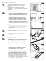
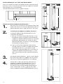
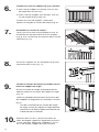
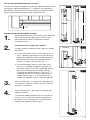
1.
2.
3.
4.
Closely follow Post Install Kit installation
instructions or use a Post Jacket on an existing
wood 4x4.
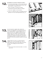
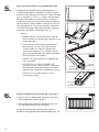
Bracket Dovetail Installation:
Install base trim over post sleeves rst.
a. For 36" high rails, place bracket dovetail install
template against the post sleeve directly on
top of the base trim and rubber band it in
place (Fig. 1).
b. For 42" high rails, top bracket dovetail will
install 37
7
⁄
7
⁄
7
8
⁄8⁄
" from the top of base trim and
bottom bracket dovetail will install 1
1
⁄
1
⁄
1
2
⁄2⁄
" from
top of base trim (Fig. 2).
With a
1
⁄
1
⁄
1
8
⁄8⁄
" drill bit, pre-drill the holes for the top
and bottom brackets (Fig. 3). Remove template
(if used).
Use 2" screws to attach top bracket dovetails.
Screws must penetrate the steel insert (if using
steel post install kit). Use 1
1
⁄
1
⁄
1
4
⁄4⁄
" screws to attach
bottom bracket dovetails (Fig. 4).
Fig. 2Fig. 1
Fig. 3
Fig. 4
Base Trim
Base Trim
Template
Template
Template
Template
Template
Template
1
1
1
1
⁄
⁄
⁄
1
⁄
1
1
⁄
1
⁄
2
⁄2⁄
2
"
"
3737
7
7
⁄
⁄
⁄
⁄
⁄
7
⁄
7
7
⁄
7
⁄
⁄8⁄
8
"
Bottom
2"
1
1
⁄
1
⁄
1
4
⁄4⁄
"
Top
LEVEL RAIL INSTALLATION:
FOR 10' RAILING ONLY:
Install enclosed screw through the bottom bracket as shown
approximately
1
⁄
1
⁄
1
2
⁄2⁄
" from the front face of the bracket, centered
vertically on the at surface.
Do this for each bottom bracket.
1
⁄
1
⁄
1
2
⁄2⁄
"

4
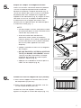
5.
6.
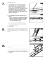
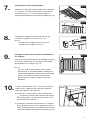
Cut Rails to Length:
Place bottom rail across post opening leaving
equivalent spacing from the last baluster and
post on each end (Fig. 5). Mark
1
⁄
1
⁄
1
2
⁄2⁄
" from end
of post to allow room for bracket width and
expansion (Fig. 6). Align top rail with bottom rail
and cut both rails with miter box or hacksaw (See
blade manufacturer's specs for correct blade) (Fig. 7).
NOTE:
• You will have to cut through an aluminum
insert in the top rail of an 8' section.
• Prior to installing round aluminum
balusters, insert the provided foam strip
into the top of the top rail and bottom of
the bottom rail
(sides opposite of routed holes).
• Cut foam strip to rail length.
•
DO NOT REMOVE THE RELEASE PAPER
FROM ENTIRE STRIP! ONLY
remove 1"
FROM ENTIRE STRIP! ONLY remove 1" FROM ENTIRE STRIP! ONLY
of the release paper from each end of the
foam strip to expose adhesive (Fig. 8).
• Press the foam strips onto rails (Fig.9).
Install 3" support brace:
a. One support brace is included with 6'
railing kits.
b. Two support braces are included with 8'
railing kits.
Install support braces evenly across span of
railing section (Fig. 10).
Fig. 5
Fig. 6
Fig. 7
3" Support Brace
Fig. 10
Press
Onto Rail
Fig. 9
Release Paper
Top
Bottom
Foam
Strip
Fig. 8

5
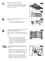
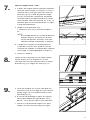
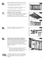
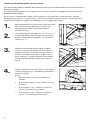
7.
Assemble Railing Section:
Lay bottom rail on a clean smooth surface and
snap balusters into routed holes (Fig. 11). Then
repeat the process to connect the top rail (Fig. 12).
9.
10.
8.
Hang Assembled Rail Section onto Dovetails:
Slide assembled rail section straight down between
both posts, and onto each dovetail (Fig. 14).
NOTE:
For railing sections using aluminum balusters
the installer will have to carefully hold top and
bottom railings together to make sure section
does not separate. (Aluminum balusters do
not come with lock tabs)
Install four 2" screws though the bottom of the top
rail brackets into handrail.
a. Pre-drill all four holes with a
5
⁄
5
⁄
5
32
⁄32⁄
" drill bit. Install
the rst two screws straight (90 degrees)
through the pre-drilled holes in the bottom of
the bracket.
b. Install the next two screws at 45 degrees
through the brackets into the post, starting
with the dimples on the bottom of the top rail
bracket (Fig. 15).
Slide brackets onto ends of rails (top and bottom)
(Fig. 13).
NOTE:
DO NOT screw bracket into top rail until you
reach Step 10.
Fig. 13
Fig. 15
Fig. 14
Fig. 11
Fig. 12

6
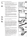
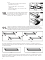
1.
2.
For angled rail installation other than at 90
degrees or 180 degrees, purchase angle
brackets.
Closely follow Post Install Kit installation
instructions or use a Post Jacket on an existing
wood 4x4.
Install base trim over post sleeves rst.
a. For the post where the angled bracket will be
installed, measure from the top of the base
trim to the bottom of the already installed top
rail (Fig. 1).
b. Mark this location on the side of the post
where the angled bracket will be installed.
Bases should align with installed rail section.
c. While holding bracket base against post,
mark with a pencil the four screw holes for the
angled bracket placement on this post (Fig. 2).
NOTE:
The measurement from the top of the base
trim to the bottom of the top rail is the location
of the bottom of the top rail brackets for all
following rails.
ANGLED RAIL INSTALLATION:
3.
With a
1
⁄
1
⁄
1
8
⁄8⁄
" drill bit, pre-drill the holes for the top
and bottom brackets.
4.
Install angled bracket bases to post with
2" screws.
5.
Fig. 3
Fig. 4
Fig. 5
Press
Onto Rail
Fig. 7
Release Paper
Foam
Strip
Fig. 6
Cut Rails to Length:
Place bottom rail across post opening leaving
equivalent spacing from the last baluster and
post on each end (Fig. 3). Mark 2" from end
of post to allow room for bracket width and
expansion (Fig. 4). Align top rail with bottom rail
and cut both rails with miter box or hacksaw (See
blade manufacturer's specs for correct blade) (Fig. 5).
NOTE:
• You will have to cut through an aluminum
insert in the top rail of an 8' section.
• Prior to installing round aluminum balusters,
insert the provided foam strips into the top
of the top rail and bottom of the bottom rails
(sides opposite of routed holes). Cut to rail
length. Then, remove 1" of the release paper
from each end to expose adhesive (Fig. 6).
Press t the foam strips to rails (Fig. 7). DO
NOT remove the release paper from entire strip
– Only remove 1" from each end.
Base
Mark
Holes
Installed Rail Section
Fig. 2
Fig. 1

7
6.
Install 3" support brace:
a. One support brace is included with 6'
railing kits.
b. Two support braces are included with 8'
railing kits.
Install support braces evenly across span of
railing section (Fig. 8).
3" Support Brace
Fig. 8
7.
Assemble Railing Section:
Lay bottom rail on a clean smooth surface and
snap balusters into routed holes (Fig. 9). Then
repeat the process to connect the top rail (Fig. 10).
8.
Slide brackets onto ends of rails (top and bottom)
(Fig. 11).
Fig. 11
Fig. 12
Fig. 9
Fig. 10
9.
10.
Place Assembled Rail Section over Angled
Bracket Bases:
Slide assembled rail section straight between both
posts, and over each angled bracket base (Fig. 12).
Slide provided pins in top/bottom angled brackets
to lock angled brackets to base.
NOTE:
When installing angled rail and connecting the
rail section, the angled bracket base needs
to be ipped on the opposite post based on
direction of the install.
Install two 1
1
⁄
1
⁄
1
4
⁄4⁄
" screws into the sides of each top
angled bracket, securing it to the handrail. Insert
screw caps onto each top bracket.

8
This guide outlines installation methods for installing
Premier Railing Stair Kits
in a variety of angles.
It is very important to identify the angle of your stairs, as the installation methods vary depending on
what angle the stair is.
Within the following steps, be sure to pay close attention to the placement and utilization of the "stair
angle template" to ensure you mark and cut your rails correctly, and note orientation of all brackets
and railing in the supporting images.
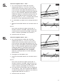
1.
2.
3.
4.
Closely follow Post Install Kit installation
instructions or use a Post Jacket on an existing
wood 4x4.
Temporarily secure a deck board (5/4") to your
stair treads to determine the spacing between the
nose of the stairs and your bottom rail (Fig. 1).
Place bottom rail on board and center the routes
between posts making sure to leave equal
distance from baluster route to post on both top
and bottom. Mark the bottom rail using inside
edge of posts (Fig. 2).
Measure angle – take rail to chop saw and
measure angle (Fig. 3). Set saw and record angle.
NOTE:
Do not cut here. This is for acquiring
measurements.
• If angle is 31º-33°, then go to Step 5
• If angle is <31°, then skip Step 5 and proceed
to Step 6
• If angle is >33°, then skip Step 5 and 6, and
proceed to Step 7
Temporary
Temporary
Temporary
Temporary
Temporary
Temporary
Deck Board
Deck Board
Deck Board
Deck Board
Deck Board
Deck Board
Deck Board
Deck Board
Deck Board
Temporary
Temporary
Temporary
Temporary
Temporary
Temporary
Deck Board
Deck Board
Deck Board
Deck Board
Deck Board
Deck Board
Deck Board
Deck Board
Deck Board
Bottom Rail
Bottom Rail
Bottom Rail
Bottom Rail
Bottom Rail
Bottom Rail
Bottom Rail
Bottom Rail
Bottom Rail
Bottom Rail
Bottom Rail
Bottom Rail
Fig. 1
Fig. 2
Fig. 3
Temporary
STAIR RAIL INSTALLATION:

9
5.
6.
For angles 31º-33°:
a. From the original line created by the post,
mark another line
11
⁄
11
⁄
11
16
⁄16⁄
" on the inside of the
bottom rail (closer to the baluster routes)
(Fig. 4). This is accomplished by using the
angle template (Fig. 5). This additional removal
of material will allow for bracket clearance
when the rail is installed. For this 31º-33°
angle, the new line will be parallel to the
previously drawn line.
b. Chop saw should already be set at 32°
c. Cut the bottom rail on the new mark at a 32°.
NOTE:
If your cut will result in a baluster
route hole being cut through, repeat
Step 3 and add/subtract a baluster
route hole, re-center, mark and proceed
to Step 4.
d. Go to Step 8.
For angles 26º-31°:
a. From the original line created by the post,
mark another line
11
⁄
11
⁄
11
16
⁄16⁄
" on the inside of the
bottom rail (closer to the baluster routes)
(Fig. 6). This is accomplished by using the
angle template (Fig. 7). This additional removal
of material will allow for bracket clearance
when the rail is installed. For this 26º-31°
angle, the new line will NOT be parallel to the
previously drawn line.
b. Set chop saw at 32°
c. Cut the bottom rail on the new mark at a 32°.
NOTE:
If your cut will result in a baluster
route hole being cut through, repeat
Step 3 and add/subtract a baluster
route hole, re-center, mark and proceed
to Step 4.
d. The rail will not match the angle of the stair,
but instead match the inside of the bracket.
The outside of the brackets will be cut to the
proper angle in Step 11.
e. Go to Step 8.
Fig. 4
Fig. 6
pg-07_fig-05_angle-template Sunday, March 08, 2015 12:24:02 PM Jay Harnish
pg-07_fig-05_angle-template Sunday, March 08, 2015 12:24:02 PM Jay Harnish
Fig. 5
Fig. 7
Original LineOriginal Line
31-33º
31-33º
31-33º31-33º
Original LineOriginal Line
Less than 31º
Less than 31º
Less than 31º
Less than 31º
Original LineOriginal Line
31-33º31-33º
Original LineOriginal Line
Less than 31º
Less than 31º
Less than 31º
Less than 31º
Mark Here
Mark Here
(32º)(32º)
Mark Here
Mark Here
(32º)(32º)
Mark Here
Mark Here
(32º)(32º)
Mark Here
Mark Here
(32º)(32º)

10
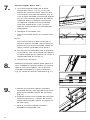
7.
8.
9.
For angles 34º-38°:
a. From the original line created by the post,
mark another line
11
⁄
11
⁄
11
16
⁄16⁄
" on the inside of the
bottom rail (closer to the baluster routes)
(Fig. 8). This is accomplished by using the
angle template (Fig. 9). This additional removal
of material will allow for bracket clearance
when the rail is installed. For this 34º-38º
angle, the new line will NOT be parallel to the
previously drawn line.
b. Set chop saw at 32°
c. Cut the bottom rail on the new mark at a 32°.
NOTE:
If your cut will result in a baluster route hole
being cut through, repeat Step 3 and add/
subtract a baluster route hole, re-center,
mark and proceed to Step 4.
d. The rail will not match the angle of the stair,
but instead match the inside of the bracket.
The outside of the brackets will be cut to the
proper angle in Step 11.
e. Go to Step 8.
Place top rail at on table. Lay the cut bottom rail
on top of the top rail, with the routed holes facing
in the same direction (Fig. 10). Line up the routes
(Fig. 11).
a. Mark the top rail (using the bottom rail and a
steel rule as a guide) to the top edge of the rail
(Fig. 12).
b. Make sure to extend the line out at the angle
to the edge of the rail (mark line on "bump" of
bottom of top rail on angle, not straight down).
c. Cut the top rail to the lines using the chop saw
set to 32°.
Fig. 10
Fig. 11
Fig. 12
Fig. 8
pg-07_fig-05_angle-template Sunday, March 08, 2015 12:24:02 PM Jay Harnish
Fig. 9
Original LineOriginal Line
More than 33º
More than 33º
More than 33º
Original LineOriginal Line
More than 33º
More than 33º
More than 33º
Mark Here
Mark Here
(32º)(32º)
Mark Here
Mark Here
(32º)(32º)
Bottom
Bottom
Rail
Rail
Bottom
Bottom
Rail
Rail
Top RailTop Rail
Top RailTop Rail

11
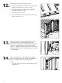
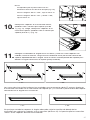
10.
11.
Place brackets on bottom rail, securing with 2
screws per bracket (#10 x 1") (Fig. 14). Then,
place brackets on top rail, securing with one
screw per bracket (#10 x 1") (Fig. 15.
Set chop saw to stair angle and carefully cut all four brackets as shown. Be particularly
careful to cut from the proper side of the bracket, depending on your angle. Cut smallest
amount of bracket possible to get the correct angle on bracket (feather to edge).
NOTE:
Make sure bottom of rails are ush against
saw fence (Fig. 13).
For angles 31º-33° go to Step 12.
For angles 26º-31º and 33º-38º go to Step 10.
Fig. 13
Fig. 14
Fig. 15
The cuts outlined above give you the results below. The angle cut on the rail matches the inside of
the bracket (32°). The bracket outside cut matches the installation angle.
Once the brackets have been cut to the proper angle, remove the screws from underneath the rails
holding the brackets to the rails (from Step 10). This allows the rails to " oat" in the brackets during
assembly.
CorrectCorrect
Incorrect
Incorrect
Top RailTop Rail
30º30º
26º26º
30º30º
26º26º
30º30º
26º26º
30º30º
26º26º
Bottom Rail
Bottom Rail
< 31º
Top RailTop Rail
38º38º
34º34º
38º38º
34º34º
38º38º
34º34º
38º38º
34º34º
Bottom Rail
Bottom Rail
> 33º
> 33º
< 31º

12
12.
13.
14.
Assemble your stair railing section:
a. Lock tabs on baluster/spindle must face outer
edge of routed holes in rails (Fig. 16).
b. Assemble your stair section by snapping
balusters/spindles in rails.
c. Place brackets on ends.
d. Place assembled stair rail between posts on
spacer board (Fig. 17).
Make sure rail brackets are centered on posts.
Drive two (#10 x 2") mounting screws into
brackets and into posts, starting with the bottom
rail (Fig. 18). Repeat for each bracket. Screw
holes are angled inwards to provide clearance for
the drill chuck. Removal of the bottom stair tread
is not required.
Two screws (#10 x 1") per bracket are driven
under the top rail (Fig. 19). Holes are angled to
allow an extension bit to clear balusters.
NOTE:
Screws are not required in the bottom of the
bottom rail.
Fig. 16
Fig. 17
Fig. 18
Fig. 19
Lock Tabs
Lock Tabs
Outer Edge Outer Edge
Holes
Holes

13

Kit de rampe horizontale et
Kit de rampe horizontale et
de rampe d’escalier Premier
de rampe d’escalier Premier
de rampe d’escalier Premier
BOM-34107816
Lire toutes les instructions avant d’installer le produit.
Consulter les consignes de sécurité du fabricant lors de l’utilisation d'outils.
Pour enregistrer le produit, visiter :
barretteoutdoorliving.com
INSTRUCTIONS D’INSTALLATION
INSTRUCTIONS D’INSTALLATION
INSTRUCTIONS D’INSTALLATION
• English
• English
• English
......................................................................................................
......................................................................................................
1
• Français
• Français
• Français
..................................................................................................
14
• Español
• Español
• Español
...................................................................................................
...................................................................................................
27

15
AVERTISSEMENT :
• Une mauvaise installation du produit peut causer des blessures. Toujours porter des lunettes de sécurité
lors de la coupe, du perçage et de l’assemblage du produit.
• Une installation incorrecte est susceptible de causer des dommages au produit ou des blessures à la
personne qui en fait l’installation.
NOTE :
• NE PAS assembler le produit s’il y a des pièces manquantes ou endommagées.
• NE PAS retourner le produit au magasin. Pour obtenir de l’aide ou des pièces de remplacement,
composer le 1-800-336-2383.
Ruban à mesurer
Niveau
Scie à métaux
Maillet de caoutchouc
Perceuse
Embout carré no 2
Mèche
1
⁄
1
⁄
1
8
⁄8⁄
po (3,2 mm)
Crayon
Planche de terrasse
temporaire
Lunettes de sécurité
OUTILS NÉCESSAIRES :
Description
Main courante
Lisse
Barreaux
Cale de support
Supports de niveau
Supports d’escalier
Supports d’angle de gauche/de droite*
Vis à prise carrée 1
1
⁄
1
⁄
1
4
⁄4⁄
po (32 mm)
Vis à prise carrée 2 po (50 mm)
Vis à prise carrée 1 po (25 mm)
Garniture de base*
Gabarits
Bandes adhésives en mousse
Composantes de rampe et
de rampe d’escalier :
*Vendue séparément
AVANT DE COMMENCER :
Main courante
Supports de niveau
Supports d’escalier
Supports d’angle
Gabarit de support
Bande adhésive en mousse pour barreaux en aluminium
Gabarit de support d’escalier
Lisse
Lisse
Cale de support
Garniture de base
Barreaux
Barreaux
Barreaux
Barreaux
Barreaux
Barreaux
Barreaux
Barreaux
Kit de rampe
Kit de rampe d'escalier
Main courante
Vis
Barreaux
Barreaux
Barreaux
Barreaux
Barreaux
Barreaux
Barreaux
Barreaux
Les poteaux de rampe en vinyle doivent
être renforcés à l’intérieur à des ns de
support de charge. Ainsi, on doit utiliser
un kit d'installation de poteau ou un
poteau en bois dans un manchon de
poteau. Le kit d'installation de poteau
et les poteaux en bois sont vendus
séparément.
Vue en plan du manchon de poteau
Vue en plan du manchon de poteau
Main
Main
courante
courante
courante
courante
courante
courante
courante
courante
courante
courante
Kit
d’installation
de poteau
acheté
Pour obtenir et examiner une copie de la garantie, visiter : BarretteOutdoorLiving.com/warranty. On peut
également composer le
1-800-336-2383
ou envoyer une lettre à Barrette Outdoor Living, 7830 Freeway
Circle, Middleburg Heights, Ohio 44130 pour demander une copie de la garantie.

16
1.
2.
3.
4.
Bien suivre les instructions d’installation du kit de
poteau ou utiliser un manchon de poteau pour un
poteau existant 4 po x 4 po (102 mm x 102 mm).
Installation du support en queue d’aronde :
Installer d’abord la garniture de base sur les
manchons de poteau.
a. Dans le cas d’une rampe de 36 po (91,4 cm)
de hauteur, placer le gabarit d’installation de
support en queue d’aronde contre le manchon
de poteau, directement sur le dessus de la
garniture de base, et utiliser un élastique pour
le maintenir en place (Fig. 1).
b. Dans le cas d’une rampe de 42 po (106,6
cm) de hauteur, installer le support en queue
d’aronde du haut à 37
7
⁄
7
⁄
7
8
⁄8⁄
po (96,2 cm) du
dessus de la garniture de base, et installer le
support en queue d’aronde du bas à 1
1
⁄
1
⁄
1
2
⁄2⁄
po
(38,1 mm) du dessus de la garniture de base
(Fig. 2).
Au moyen d’une mèche de
1
⁄
1
⁄
1
8
⁄8⁄
po (3,2 mm), percer
des avant-trous pour les supports du haut et du
bas (Fig. 3). Enlever le gabarit (le cas échéant).
Utiliser des vis de 2 po (50 mm) pour xer les
supports en queue d’aronde du haut. Les vis
doivent pénétrer la pièce insérée en acier (si
on utilise la trousse d’installation de poteau en
acier). Utiliser des vis de 1
1
⁄
1
⁄
1
4
⁄4⁄
po (32 mm) pour
xer les supports en queue d’aronde du bas (Fig. 4).
Fig. 2Fig. 1
Fig. 3
Fig. 4
Garniture de baseGarniture de base
Gabarit
Gabarit
38,1
38,1
mm
mm
96,2 cm96,2 cm
Bas
50 mm
32 mm
Haut
INSTALLATION DE RAMPE HORIZONTALE :
POUR RAMPES DE 10 PI (305 CM) SEULEMENT :
Fixer la vis fournie à travers le support du bas (comme illustré)
à environ
1
⁄
1
⁄
1
2
⁄2⁄
po (11 mm) de la face avant du support et centrée
verticalement sur la surface plane.
Faire de même pour tous les supports du bas.
1
⁄
1
⁄
1
2
⁄2⁄
"

17
5.
6.
Couper les rampes à la longueur désirée :
Placer la lisse dans l’ouverture entre les poteaux
; laisser un espace équivalent entre le dernier
barreau et le poteau à chaque extrémité (Fig. 5).
Laisser un espace de
1
⁄
1
⁄
1
2
⁄2⁄
po (12 mm) à l’extrémité
du poteau pour tenir compte de la largeur du
support et de la dilatation (Fig. 6). Aligner la main
courante sur la lisse, et couper les deux pièces
à l’aide d’une scie à onglets ou d’une scie à
métaux [voir les spéci cations du fabricant pour
le choix de la lame] (Fig. 7).
NOTE:
• On doit couper à travers une pièce insérée
en aluminium dans la main courante d’une
section de 8 pi (243,8 cm).
• Avant d’installer des barreaux en
aluminium ronds, placer la bande en
mousse fournie sur la partie supérieure de
la main courante et sur la partie inférieure
de la lisse (côtés opposés aux trous
toupillés).
• Couper la bande en mousse à la longueur
des rampes.
•
NE PAS ENLEVER L’INTERCALAIRE SUR
TOUTE LA BANDE. SEULEMENT
enlever
1 po (25 mm) de l’intercalaire à chaque
extrémité de la bande en mousse pour
exposer l’adhésif (Fig. 8).
• Appuyer sur la bande en mousse pour la
coller sur les rampes (Fig. 9).
Installer les cales de support de 3 po (76 mm) :
a. Une cale de support est fournie avec les kits
de rampe de 6 pi (183 cm).
b. Deux cales de support sont fournies avec les
kits de rampe de 8 pi (244 cm).
Installer les cales de support à intervalles
réguliers le long de la section de rampe (Fig. 10).
Fig. 5
Fig. 6
Fig. 7
Cale de support 3 po (76 mm)
Fig. 10
Coller sur
la rampe
Fig. 9
Intercalaire
Dessus
Bas
Bande en
mousse
Fig. 8

18
7.
Assembler la section de rampe :
Placer la lisse sur une surface propre et lisse, et
enclencher les barreaux dans les trous toupillés
(Fig. 11). Puis, enclencher les barreaux dans la
main courante (Fig. 12).
9.
10.
8.
Installer la section de rampe assemblée sur les
supports en queue d’aronde:
Glisser la section de rampe assemblée entre les
poteaux jusque sur les supports en queue d’aronde
(Fig. 14).
NOTE:
Dans le cas des sections de rampe avec
barreaux en aluminium, l’installateur doit
s’assurer de bien tenir ensemble le haut et le
bas de la section de rampe pour éviter que
les barreaux ne s’écartent (les barreaux en
aluminium ne sont pas munis de pattes de
blocage).
Enfoncer quatre vis de 2 po (50 mm) à travers la
partie inférieure des supports jusque dans la main
courante.
a. Utiliser une mèche de
5
⁄
5
⁄
5
32
⁄32⁄
po (4 mm) pour percer
les quatre avant-trous. Enfoncer les deux
premières vis à un angle de 90 degrés dans les
avant-trous de la partie inférieure du support.
b. Enfoncer les deux autres vis à un angle de
45 degrés à travers le support jusque dans
le poteau, à partir des fossettes sur la partie
inférieure du support de main courante (Fig. 15).
Glisser les supports sur les extrémités de la main
courante et de la lisse (Fig. 13).
NOTE:
NE PAS visser le support dans la main
courante avant d’avoir atteint Étape 10.
Fig. 13
Fig. 15
Fig. 14
Fig. 11
Fig. 12

19
1.
2.
Pour une installation en angle (autre qu’à 90° ou
180°), acheter des supports d’angle.
Bien suivre les instructions d’installation du kit de
poteau ou utiliser un manchon de poteau pour un
poteau existant 4 po x 4 po (102 mm x 102 mm).
Installer d’abord la garniture de base sur les
manchons de poteau.
a. Dans le cas du poteau où sera installé le
support en angle, mesurer du dessus de la
garniture de base jusqu’à la partie inférieure de
la main courante déjà installée (Fig. 1).
b. Marquer cet emplacement sur le côté du
poteau. La base des supports devrait être
alignée sur la section de rampe installée.
c. En tenant la base du support contre le poteau,
utiliser un crayon pour marquer l’emplacement
sur le poteau des quatre trous de vis pour le
support en angle (Fig. 2).
NOTE:
La mesure à partir du dessus de la garniture
de base jusqu’au bas de la main courante
indique l’emplacement du bas des supports
de main courante pour toutes les sections de
rampe à venir.
INSTALLATION DE RAMPE EN ANGLE :
3.
Au moyen d’une mèche de
1
⁄
1
⁄
1
8
⁄8⁄
po (3,2 mm), percer
des avant-trous pour les supports du haut et du bas.
4.
Fixer les bases de support en angle au poteau à
l’aide de vis de 2 po (50 mm).
5.
Fig. 3
Fig. 4
Fig. 5
Coller sur
la rampe
Fig. 7
Intercalaire
Bande en
mousse
Fig. 6
Couper les rampes à la longueur désirée :
Placer la lisse dans l’ouverture entre les poteaux
en laissant un espace équivalent entre le dernier
barreau et le poteau à chaque extrémité (Fig. 3).
Laisser un espace de 2 po (50 mm) à l’extrémité
du poteau pour tenir compte de la largeur du
support et de la dilatation (Fig. 4). Aligner la main
courante sur la lisse et couper les deux pièces
à l’aide d’une scie à onglets ou d’une scie à
métaux [voir les spéci cations du fabricant pour
le choix de la lame] (Fig. 5).
NOTE:
• On doit couper à travers une pièce insérée en
aluminium dans la main courante d’une section
de 8 pi (243,8 cm).
• Avant d’installer des barreaux en aluminium
ronds, placer la bande en mousse fournie sur la
partie supérieure de la main courante et sur la
partie inférieure de la lisse (côtés opposés aux
trous toupillés). Couper la bande en mousse à
la longueur des rampes. Puis, enlever 1 po (25
mm) de l’intercalaire à chaque extrémité de la
bande en mousse pour exposer l’adhésif (Fig.
6). Appuyer sur la bande en mousse pour la
coller sur les rampes (Fig. 7). NE PAS enlever
l’intercalaire sur toute la bande.
– Seulement enlever 1 po (25 mm) à chaque
extrémité de la bande.
Base
Section de rampe installée
Fig. 2
Fig. 1
Emplacement
Emplacement
Emplacement
Emplacement
Emplacement
Emplacement
des trous
des trous
des trous
des trous
des trous
des trous

20
6.
Installer les cales de support de 3 po (76 mm) :
a. Une cale de support est fournie avec les kits
de rampe de 6 pi (183 cm).
b. Deux cales de support sont fournies avec les
kits de rampe de 8 pi (244 cm).
Installer les cales de support à intervalles
réguliers le long de la section de rampe (Fig. 8).
Cale de support 3 po (76 mm)
Fig. 8
7.
Assembler la section de rampe :
Placer la lisse sur une surface propre et lisse, et
enclencher les barreaux dans les trous toupillés
(Fig. 9). Puis, enclencher les barreaux dans la main
courante (Fig. 10).
8.
Glisser les supports sur les extrémités de la main
courante et de la lisse (Fig. 11).
Fig. 11
Fig. 9
Fig. 10
9.
10.
Installer la section de rampe assemblée sur les
bases de support en angle :
Glisser la section de rampe assemblée entre les
poteaux jusque sur les bases de support en angle
(Fig. 12).
Insérer les goupilles fournies dans le haut et le bas
des supports en angle pour les verrouiller à la base.
NOTE:
Lors de l’installation d’une section de rampe
en angle, la base du support en angle doit être
retournée sur le poteau opposé en fonction de
la direction de l’installation.
Enfoncer deux vis de 1
1
⁄
1
⁄
1
4
⁄4⁄
po (32 mm) dans les
côtés de chaque support en angle pour les xer à
la main courante. Mettre des chapeaux à vis sur
les vis de chaque support de main courante.
Fig. 12
La page est en cours de chargement...
La page est en cours de chargement...
La page est en cours de chargement...
La page est en cours de chargement...
La page est en cours de chargement...
La page est en cours de chargement...
La page est en cours de chargement...
La page est en cours de chargement...
La page est en cours de chargement...
La page est en cours de chargement...
La page est en cours de chargement...
La page est en cours de chargement...
La page est en cours de chargement...
La page est en cours de chargement...
La page est en cours de chargement...
La page est en cours de chargement...
La page est en cours de chargement...
La page est en cours de chargement...
La page est en cours de chargement...
La page est en cours de chargement...
-
 1
1
-
 2
2
-
 3
3
-
 4
4
-
 5
5
-
 6
6
-
 7
7
-
 8
8
-
 9
9
-
 10
10
-
 11
11
-
 12
12
-
 13
13
-
 14
14
-
 15
15
-
 16
16
-
 17
17
-
 18
18
-
 19
19
-
 20
20
-
 21
21
-
 22
22
-
 23
23
-
 24
24
-
 25
25
-
 26
26
-
 27
27
-
 28
28
-
 29
29
-
 30
30
-
 31
31
-
 32
32
-
 33
33
-
 34
34
-
 35
35
-
 36
36
-
 37
37
-
 38
38
-
 39
39
-
 40
40


dans d''autres langues
- English: Veranda 73045452 Installation guide
- español: Veranda 73045452 Guía de instalación
Documents connexes


Autres documents
-
Freedom 73025526 Guide d'installation
-
RDI 73019087 Guide d'installation
-
Deckorators 346969 Guide d'installation
-
-
Barrette Outdoor Living 73050447 Manuel utilisateur
-
 Colonial Elegance SKBN455 Mode d'emploi
-
DeckoRail 147711 Guide d'installation
-
Fortress Technologies PURE VIEW GLASS BALUSTER FOR Fe26 STEEL Installation Instructions Manual
-
Unbranded 125899 Guide d'installation
-
 ProWood 163403 Mode d'emploi

