Fortress Technologies PURE VIEW GLASS BALUSTER FOR Fe26 STEEL Installation Instructions Manual
- Taper
- Installation Instructions Manual

PURE VIEW: Fe
26
GLASS BALUSTER INSTALLATION
1
PURE VIEW GLASS BALUSTER FOR Fe
26
STEEL
INSTALLATION INSTRUCTIONS
Pure
View®
PURE VIEW GLASS BALUSTER FOR Fe
26
STEEL
INSTALLATION INSTRUCTIONS
PANNEAUX À BALUSTRES DE VERRE PURE VIEW POUR SYSTÈME EN ACIER Fe
26
INSTRUCTIONS D’INSTALLATION

2
PURE VIEW: Fe
26
GLASS BALUSTER INSTALLATION
English
Introducon.........................................................................3
UniversalBracket(UB).............................................4
CollarBracket(CB).................................................16
AngledBracket(UB&CB)......................................20
Stair Bracket (UB & CB)..........................................28
Care&Maintenance..............................................40
Warranty.................................................................41
Español
Introducción...........................................................................3
Soporte universal (UB)...............................................4
Soporte de collarín (CB)............................................16
Soporte en ángulo (UB y CB)....................................20
Soporte de escalera (UB y CB)..................................28
Cuidado y mantenimiento........................................40
Garana.................................................................... 41
Français
Introducon.........................................................................3
Ferrureuniverselle(FU)...........................................4
Ferrureàcollier(FC)..............................................16
Ferrureàangle(FU&FC)......................................20
Ferrure pour escalier(FU&FC).............................28
Entreen................................................................40
Garane.................................................................41
TABLE OF CONTENTS

PURE VIEW: Fe
26
GLASS BALUSTER INSTALLATION
3
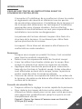
INTRODUCTION
READ INSTRUCTIONS COMPLETELY BEFORE
STARTING INSTALLATION
It is the responsibility of the installer to meet all code and
safety requirements, and to obtain all required building
permits.Thedeckandrailinginstallershoulddetermine
andimplementappropriateinstallaontechniquesfor
eachinstallaonsituaon.FortressRailingProductsandits
distributors shall not be held liable for improper or unsafe
installaons.
FortressPostsmustalwaysbesecuredtothedeck
framingandshouldneverbeaachedtoonlythedeck
boards.
PureViewI-SupportisrequiredforCanadian
CodeCompliance.
Note
WhencungFortressrailing,itisveryimportantto
completethefollowingatcutpoints:
• Removeallmetalshavingsfromthecutarea.
• Fileanysharpedgeslebycung.Thoroughlywipeand
removeanylings,grime,ordirtfromtherailing.
• ApplytwocoatsofFortresszincbasedtouch-uppaintto
thecutarea.Iftouchupisatrailends,allowpainttodry
beforeconnecngbrackettopost.
• Be sure to remove any metal shavings from the surface of
deck,pao,orbalconytopreventstainsonthedeck
surface.
Torx Safety Tips
• Alwaysusethelowestspeedsengondrill.
• Toreducechanceofbitbreakage,startghteningwithdrill
onlowtorquesengandworkupunlscrewissecured.
Tip: Pre-drill holes with 3/16” [4.5mm] drill bit.

4
PURE VIEW: Fe
26
GLASS BALUSTER INSTALLATION
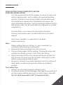
Required Tools
Goggles
Drill
Tape
Measurer
Level
Tool
Speed
Square
Touch-Up
Paint
MetalCung
MiterSaw
T-25
Driver Bit
#2Phillips
Head Bit
Bit
Extender
DrillBits:
1/16”,3/16”,3/8”,
[1.5mm,4.5mm,9.5mm]
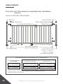
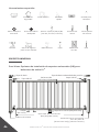
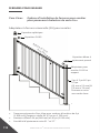
Pure View: Fe
26
Glass Baluster Universal (UB) Brackets
InstallaonOpon
Pencil
Rubber
Mallet
Ball Cap
UB-05Cap
PressedDomeCap
Base Cover
UB-05Cup
3-3/4”[95.5mm]I-Support
Spring
Punch
Safety
Gloves
2”x4”
Wood
3-3/4”
[95.5mm]
2”X2”&3”X3”
[51mmx51mm]&
[76mmx76mm]IronPostsWithBase
PureView:SteelRail
69-1/2”[1765.5mm]
PureView
Glass Baluster
File
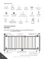
UNIVERSAL BRACKET

PURE VIEW: Fe
26
GLASS BALUSTER INSTALLATION
5
*Installed heights include a 3-3/4”[95.5mm]spacebetweendecksurface
andboomedgeofboomrail.
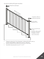
Universal Bracket (UB)PostConguraon
34”[864mm]
40”[1016mm]
38-1/16”[967mm]
43-7/8”[1114mm]
39-1/2”[1003mm]
45-1/2”[1156mm]
Fe
26
Pure View Baluster
Panel Height
Rail Panel
InstalledPanelHeight* RequiredPost
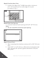
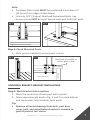
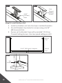
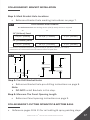
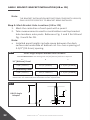
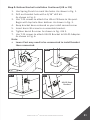
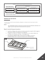
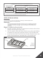
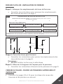
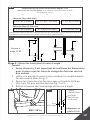
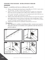
Step 1: Install Wood Blocks
1. InstallWoodBlocklevelwithtopofjoist.AsshowninFig.1(A)
2. SecureWoodBlocktoblockingonallfoursideswith#10X
3-1/2”[89mm]deckscrews.
• WoodBlockmustbeconstructedwithtreateddimensional
lumberwithaminimumthicknessof11/2”[38mm].
POST MOUNTING
*IfusingFortressEvoluonFraming,contactFortressforinstrucons.
Note:
It’s recommended to install brackets into post before post
mounng.Referencepage7forbracketInstallaonsteps.
Fig. 1
#10x3-1/3”
[84.5mm]
(A)
(A)
Joist
Blocking

6
PURE VIEW: Fe
26
GLASS BALUSTER INSTALLATION
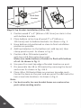
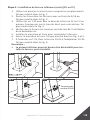
Step 2: PosionBasePlate
1. PosiontheedgeofAL
13
HOME base plate a minimum
of½”[12.5mm]fromtheinsideedgeofrimjoist.
AsshowninFig.1.
Fig. 1
1/2”[12.5mm]
1/2”
[12.5mm]
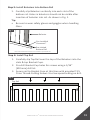
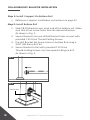
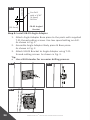
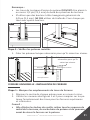
Step 4: Mount Posts
1. Markmounngholelocaonsandpre-drilla3/8”[9.5mm]
hole.
2. Insert3/8”x3-1/2”[9.5mmx89mm]HexHeadgalvanized
boltsthrough3/8”[9.5mm]galvanizedwasherandpost
baseplate.
Fig. 1
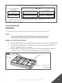
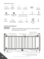
Step 3: Max Post Spacing
• 6’panelmaximumpostspacingis69-3/4”[1771.5mm].
Note:
• Do not exceed the maximum post spacing.
6’panelmaximumpostspacingis69-3/4”
[1771.5mm]

PURE VIEW: Fe
26
GLASS BALUSTER INSTALLATION
7
Note:
• PostBasePlateholesMUSTbeposionedaminimum½”
[12.5mm]fromedgeofdeckboard.
• Useonly3/8”[9.5mm]HexHeadGalvanizedBolts.Lag
ScrewsshouldNOTbeused.Secureeachpostwithfourbolts.
Fig. 1 Fig. 2
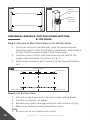
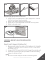
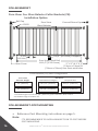
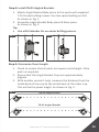
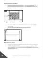
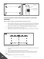
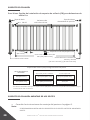
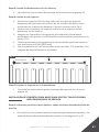
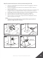
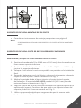
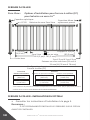
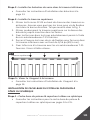
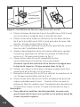
OTP and Proud Post: Max Post Spacing
• 8’ panel maximum post spacing is 93-7/8”.
• 6’ panel maximum post spacing is 69-7/8”.
Note: Do not exceed the maximum post spacing.
8’ Panel max post spacing 93-7/8”
6’ Panel max post spacing 69-7/8”
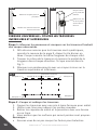
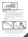
OTP and Proud Post: Measuring The Panel Opening Length
• Measure the distance of the panel opening.
• Measure from the back wall of the bracket to the back wall of the bracket on other post.
• Confirm that the measurements for the top brackets are the same as the bottom brackets.
Measure the panel opening
Not here
Measure from
back of bracket
Check measurement with top
3/12
OTP and Proud Post: Max Post Spacing
• 8’ panel maximum post spacing is 93-7/8”.
• 6’ panel maximum post spacing is 69-7/8”.
Note: Do not exceed the maximum post spacing.
8’ Panel max post spacing 93-7/8”
6’ Panel max post spacing 69-7/8”
OTP and Proud Post: Measuring The Panel Opening Length
• Measure the distance of the panel opening.
• Measure from the back wall of the bracket to the back wall of the bracket on other post.
• Confirm that the measurements for the top brackets are the same as the bottom brackets.
Measure the panel opening
Not here
Measure from
back of bracket
Check measurement with top
3/12
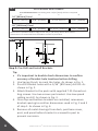
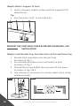
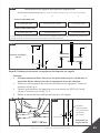
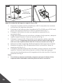
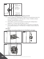
Step 1: MarkBracketHoleLocaons
1. Markthecenterlineofeachpostwithapencil.
2. TakemeasurementsusedinFig.1and2tomarkboom
andtopbracketholelocaonsontoposts.
Tip:
• Remove all metal shavings from deck, post base
cover, post, and panel before bracket is screwed to
post to prevent rust stains.
UNIVERSAL BRACKET: BRACKET INSTALLATION
Step 5: Check Mounted Posts
1. Shimpostasneededtoensurepostislevel.
Fig. 1
Fig. 2
Shim post as needed to
ensure post is level
Deck Board
RimJoist
Joist/Blocking
Wood Block
1/2”
[12.5
mm]

8
PURE VIEW: Fe
26
GLASS BALUSTER INSTALLATION
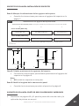
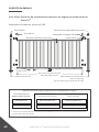
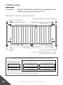
5/8”[16mm]
37-1/8”[943mm]
*DimensionAposionsboomedgeofrail3-3/4”[95.5mm]abovedecksurface.
*DimensionAismeasuredfromtheboomsurfaceofpostbase.
34” [864mm] Panel
5/8”[16mm]
42-15/16”[1090mm]
40” [1016mm] Panel
4-1/16”[103mm]
4-1/16”[103mm]
5/8”[16mm]
5/8”[16mm]
Fig. 2
B
C
B
A
B A
D
Fig. 1
UB-05BracketHoleLocaons
Pre-drill Dimensions: Pre-drillingwitha5/32”[4mm]drillbitisrequired
A*
B C D
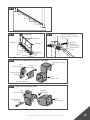
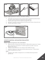
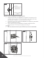
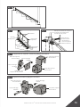
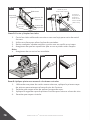
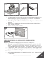
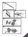
Step 2: Pre-Drill and Install Brackets
Tip:
• It’simportanttodoublecheckdimensionstoconrm
accuracyofbracketholelocaonsbeforedrilling.
1. UseSpringPunchtomarktheholes.AsshowninFig.1.
2. Pre-drillbracketholeswitha3/16”[89.5mm]drillbit.As
showninFig.2.
3. AachBrackettothepostswithsuppliedT-25thread-cut-
ngscrews.Usetwoscrewsperbracket.Uselowspeed
sengondrill.AsshowninFig.3.
4. Oncetopandboombracketsareinstalled,remeasure
bracketspacingtoconrmdimensionsusedinFig.2and3
ofstep1.AsshowninFig.4.
5. R e m o v e a l l m e t a l s h a v i n g s f r o m d e c k , p o s t b a s e c o v e r,
post,andpanelbeforebracketisscrewedtopostto
preventcorrosion.

PURE VIEW: Fe
26
GLASS BALUSTER INSTALLATION
9
Fig. 1 Fig. 2
Fig. 3
Fig. 4
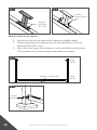
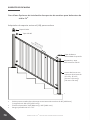
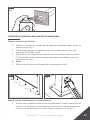
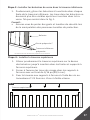
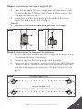
Step 3: Measure The Panel Opening Length
1. Measurethedistanceofthepanelopening.
AsshowninFig.1.
2. Conrmthatthemeasurementsforthetopbracketsarethe
sameastheboombrackets.
Note:
• Measure from the back wall of the bracket to the back wall
of the bracket on other post. As shown in Fig. 2.

10
PURE VIEW: Fe
26
GLASS BALUSTER INSTALLATION
Fig. 1
Fig. 2
Measure the panel opening
Checkmeasurementwithtop
Do not
measure from
post
Measure
from back
of bracket
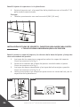
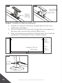
UNIVERSAL BRACKET: CUTTING DOWN BOTTOM
& TOP RAILS
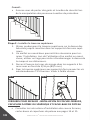
Step 1: Measure & Mark Rails Where Cuts Will Be Made
1. Toensurerailsaresymmetrical,takethemeasurement
foundonpage9,step3ofBracketInstallaon,anddivideit
inhalf.Thencutequallengthsfrombothends.
2. Find the center of the rails and measure out half of the
lengtheachdirecon.AsshowninFig.1.
3. Marktheselocaonswithapencilonthetopandboom
rail.
Fig. 1
Mark HereMark Here
Mark Here Mark Here
HalfofPanelLength
CenterofRails
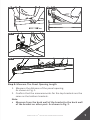
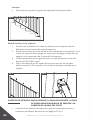
Step 2: Cut & Clean Rails
1. Cutrailsusingasawwithaferrousmetalcungblade.
2. Useletosmoothcutedges.
3. Removeanymetalshavingsanddustwithabrushorrag.
4. Makesuresurfacestobepaintedareclean.
Note:
• BesurenottocutGrommetsinrails.

PURE VIEW: Fe
26
GLASS BALUSTER INSTALLATION
11
Fig. 1
Fig. 2
Fig. 3
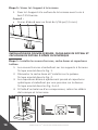
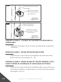
Step 3: Apply Spray Paint To Cut Areas
1. Usingapieceofcardboardasamask,applythe1
st
coat of
Fortresszincbasedtouch-uppaint.
2. Allowtodrybeforeapplyingsecondcoat.
3. Applythe2
nd
coatofFortresszincbasedtouch-uppaint.
4. Allowtodryandinstall.
Fig. 1
2X
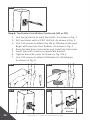
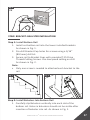
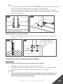
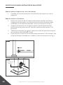
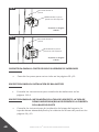
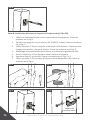
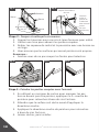
1. Measureandlocatethecenteroftheboomrail.Usingthe
I-Supportasaguide,markthecenterofthe2screwholes.
AsshowninFig.1.
2. Usinga3/16”[4.5mm]drillbit,drillthoughtheoutsidewall.
3. InstalltheI-SupportwiththeprovidedT-25threadcung
screws.AsshowninFig.2.
Note:
• BesuretoinstallI-Supportonsideofrailfacingdeck.
UNIVERSAL BRACKET: BALUSTER INSTALLATION
Step 1: InstallI-SupportOnBoomRail

12
PURE VIEW: Fe
26
GLASS BALUSTER INSTALLATION
Fig. 2
Set
Screw
Fig. 1
3/16”
[4.5mm]
Hole
Fig. 2
T-25
Thread
Cung
Screws
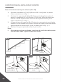
Step 2:InstallBoomRail
1. Install cut boomrailintothelowerinstalledbrackets.
2. Pre-drillBracket Cup holesforscrewsusinga3/16”
[89.5mm]drillbit.
3. SecurerailtoBracketCupswithprovidedT-25Drive
Thread-CungScrews.Uselowspeedsengondrill.
Fig. 1
UB-05
Cup
UB-05
Cup
3-3/4”[95.5mm]I-Support

PURE VIEW: Fe
26
GLASS BALUSTER INSTALLATION
13
TopRail
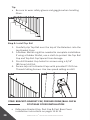
Step 3:InstallBalustersIntoBoomRail
1. CarefullyslipBalustersvercallyintoeachslotofthe
boomrail.Holesinbalustersshouldnotbevisibleaer
inseronofbalusterintorail.AsshowninFig.1.
Tip:
• Besuretowearsafetyglovesandgoggleswhenhandling
Glass.
Fig. 1
Baluster
Pre-Installed
Grommet*
Step 4: Install Top Rail
1. CarefullyslipTopRailoverthetopoftheBalustersintothe
slots&topBracketCups.
2. Pre-drillBracket Cup holesforscrewsusinga3/16”
[89.5mm]drillbit.
3. SecurerailtoBracketCupsatthismewithprovidedT-25
DriveThread-CungScrews.Uselowspeedsengondrill.
Pre-sloed
BoomRail
*PureViewStandardGrommetscomeinstalledinpre-sloedrails.
Fig. 1

14
PURE VIEW: Fe
26
GLASS BALUSTER INSTALLATION
Step 5: AachI-SupportToDeck
1. FastenI-SupporttodecksurfacewiththesuppliedT-25
WoodScrew.
Tip:
• Pre-drillwitha1/16”[1.5mm]drillbit.
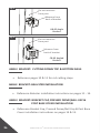
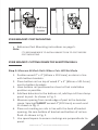
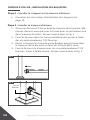
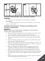
Step 1: Install Bracket Cap, Post Base Cover & Pressed Dome Cap
1. BracketCapssnapdownoverBracket Cups.
AsshowninFig.1.
2. Dis-assemblePostBaseCoverandinstallonpost.
AsshowninFig.2.
3.
PressedDomeCaps&BallCapsarepresstintoplace.
AsshowninFig.3&4.
4. Use a broom or compressor to remove debris from railing
anddecksurface.
BRACKET CAP, POST BASE COVER & PRESSED DOME/BALL CAP
INSTALLATION
Fig. 1
Fig. 1
Fig. 2

PURE VIEW: Fe
26
GLASS BALUSTER INSTALLATION
15
Fig. 3
Fig. 4

16
PURE VIEW: Fe
26
GLASS BALUSTER INSTALLATION
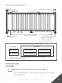
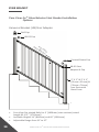
Pure View: Fe
26
Glass Baluster Collar Brackets (CB)
InstallaonOpon
Ball Cap
CB-05
PressedDomeCap
Base Cover
3-3/4”[95.5mm]I-Support
3-3/4”
[95.5mm]
2”X2”&3”X3”
[51mmx51mm]&
[76mmx76mm]IronPostswithbase
PureView:SteelRail
69-1/2”[1765.5mm]
PureView
Glass Baluster
Collar Bracket (CB) PostConguraon
*Installed heights include a 3-3/4”[95.5mm]spacebetweendecksurface
andboomedgeofboomrail.
Rail Panel
38-1/16”[967mm]
43-7/8”[1114mm]
InstalledPanelHeight*
39-1/2”[1003mm]
45-1/2”[1156mm]
RequiredPost
Pure View
Baluster Height
34”[864mm]
40”[1016mm]
COLLAR BRACKET: POST MOUNTING
• ReferencePostMounnginstruconsonpage5.
Note:
IT’SRECOMMENDEDTOINSTALLBRACKETSONTOPOSTBEFORE
POSTMOUNTING.
COLLAR BRACKET

PURE VIEW: Fe
26
GLASS BALUSTER INSTALLATION
17
COLLAR BRACKET: BRACKET INSTALLATION
Step 1: MarkBracketHoleLocaons
• ReferenceBracketholemarkinginstruconsonpage7.
Fig. 2
Step 2: Pre-Drill Bracket Holes
• ReferenceBracketholepre-drillinginstruconsonpage8.
Note:
• DO NOTinstallBracketsinthisstep.
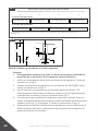
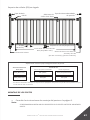
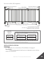
3-3/16”[81mm] 2-1/2”[63mm]36-1/2”[925mm]
30-5/8”[778mm]
3-3/16”[81mm] 2-1/2”[63mm]
Fig. 1
CB-05BracketHoleLocaons
Pre-drill Dimensions: Pre-drillingwitha3/16”[4.5mm]drillbitisrequired
A* B C
*DimensionAposionsboomedgeofrail3-3/4”[95.5mm]abovedecksurface.
*DimensionAismeasuredfromtheboomsurfaceofpostbase.
34” [864mm] Panel
40” [1016mm] Panel
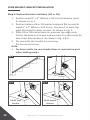
Step 3: Measure The Panel Opening Length
• ReferencePanelopeninginstruconsonpage9.
COLLAR BRACKET: CUTTING DOWN TOP & BOTTOM RAILS
• Referencepages10&11forrailcung&spray painngsteps.
A
C
C
B
C
A

18
PURE VIEW: Fe
26
GLASS BALUSTER INSTALLATION
• ReferenceI-supportinstallaoninstruconsonpage12.
COLLAR BRACKET: BALUSTER INSTALLATION
Step 1: InstallI-SupportOnBoomRail
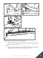
Step 2:InstallBoomRail
1. SlideCB-05Bracketsovereachendoftheboomrail.Make
surethatallsetscrewholesfacethedesireddirecon.
AsshowninFig.1.
2. SecureBracketsintopre-drilledBracketholesonpostwith
providedT-25DriveThread-CungScrews.
3. Pre-drillBracketSetScrewholesonboomRailusinga
3/16”[89.5mm]drillbit.
4. SecureBrackettoRailwithprovidedT-25Drive
Thread-CungScrews.Uselowspeedsengondrill.
AsshowninFig.2.
Fig. 1
Fig. 2
SetScrew

PURE VIEW: Fe
26
GLASS BALUSTER INSTALLATION
19
Step 3:InstallBalustersIntoBoomRail
• ReferenceBalusterinstallaoninstruconsonpage13.
Step 4: Install Top Rail
1. SlideCB-05BracketsovereachendoftheTopRail.Make
surethatallsetscrewholesfacethedesireddirecon.
AsshowninFig.1.
2. CarefullyslipTopRailoverthetopoftheBalustersintothe
slots.
3. SecureBracketsintopre-drilledBracketholesonpostwith
providedT-25DriveThread-CungScrews.
4. Pre-drillBracketSetScrewholesonboomRailusinga
3/16”[89.5mm]drillbit.
5. SecureBrackettoRailwithprovidedT-25Drive
Thread-CungScrews.Uselowspeedsengondrill.
Fig. 1
TopRail
Step 5: AachI-SupportToDeck
• ReferenceI-supportmounnginstruconsonpage14.
Step 1: Post Base Cover & Pressed Dome/Ball Cap
• ReferencePostBaseCover&PressedDome/BallCap
instruconsonpages14&15.
POST BASE COVER & PRESSED DOME/BALL CAP INSTALLATION

20
PURE VIEW: Fe
26
GLASS BALUSTER INSTALLATION
ANGLE BRACKET
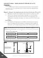
Pure View: Fe
26
GlassBalusterAngledBracketInstallaon
Opons
Ball Cap
UB-05Cap
PressedDomeCap
Base Cover
UB-05Cup
3-3/4”[95.5mm]I-Support
3-3/4”
[95.5mm]
2”X2”&3”X3”
[51mmx51mm]&
[76mmx76mm]
IronPostswithbase
PureView:SteelRail
69-1/2”[1765.5mm]
Universal Bracket (UB) Adapter
*Installed heights include a 3-3/4”[95.5mm]spacebetweendecksurface
andboomedgeofboomrail.
34”[864mm]
40”[1016mm]
38-1/16”[967mm]
43-7/8”[1114mm]
39-1/2”[1003mm]
45-1/2”[1156mm]
UniversalBracket(UB)AdapterPostConguraon
Fe
26
Pure View Baluster
Panel Height
Rail Panel
InstalledPanelHeight* RequiredPost
UB-05AngleAdapter
PureViewGlassBaluster
La page est en cours de chargement...
La page est en cours de chargement...
La page est en cours de chargement...
La page est en cours de chargement...
La page est en cours de chargement...
La page est en cours de chargement...
La page est en cours de chargement...
La page est en cours de chargement...
La page est en cours de chargement...
La page est en cours de chargement...
La page est en cours de chargement...
La page est en cours de chargement...
La page est en cours de chargement...
La page est en cours de chargement...
La page est en cours de chargement...
La page est en cours de chargement...
La page est en cours de chargement...
La page est en cours de chargement...
La page est en cours de chargement...
La page est en cours de chargement...
La page est en cours de chargement...
La page est en cours de chargement...
La page est en cours de chargement...
La page est en cours de chargement...
La page est en cours de chargement...
La page est en cours de chargement...
La page est en cours de chargement...
La page est en cours de chargement...
La page est en cours de chargement...
La page est en cours de chargement...
La page est en cours de chargement...
La page est en cours de chargement...
La page est en cours de chargement...
La page est en cours de chargement...
La page est en cours de chargement...
La page est en cours de chargement...
La page est en cours de chargement...
La page est en cours de chargement...
La page est en cours de chargement...
La page est en cours de chargement...
La page est en cours de chargement...
La page est en cours de chargement...
La page est en cours de chargement...
La page est en cours de chargement...
La page est en cours de chargement...
La page est en cours de chargement...
La page est en cours de chargement...
La page est en cours de chargement...
La page est en cours de chargement...
La page est en cours de chargement...
La page est en cours de chargement...
La page est en cours de chargement...
La page est en cours de chargement...
La page est en cours de chargement...
La page est en cours de chargement...
La page est en cours de chargement...
La page est en cours de chargement...
La page est en cours de chargement...
La page est en cours de chargement...
La page est en cours de chargement...
La page est en cours de chargement...
La page est en cours de chargement...
La page est en cours de chargement...
La page est en cours de chargement...
La page est en cours de chargement...
La page est en cours de chargement...
La page est en cours de chargement...
La page est en cours de chargement...
La page est en cours de chargement...
La page est en cours de chargement...
La page est en cours de chargement...
La page est en cours de chargement...
La page est en cours de chargement...
La page est en cours de chargement...
La page est en cours de chargement...
La page est en cours de chargement...
La page est en cours de chargement...
La page est en cours de chargement...
La page est en cours de chargement...
La page est en cours de chargement...
La page est en cours de chargement...
La page est en cours de chargement...
La page est en cours de chargement...
La page est en cours de chargement...
La page est en cours de chargement...
La page est en cours de chargement...
La page est en cours de chargement...
La page est en cours de chargement...
La page est en cours de chargement...
La page est en cours de chargement...
La page est en cours de chargement...
La page est en cours de chargement...
La page est en cours de chargement...
La page est en cours de chargement...
La page est en cours de chargement...
La page est en cours de chargement...
La page est en cours de chargement...
La page est en cours de chargement...
La page est en cours de chargement...
La page est en cours de chargement...
La page est en cours de chargement...
La page est en cours de chargement...
La page est en cours de chargement...
La page est en cours de chargement...
La page est en cours de chargement...
La page est en cours de chargement...
La page est en cours de chargement...
La page est en cours de chargement...
-
 1
1
-
 2
2
-
 3
3
-
 4
4
-
 5
5
-
 6
6
-
 7
7
-
 8
8
-
 9
9
-
 10
10
-
 11
11
-
 12
12
-
 13
13
-
 14
14
-
 15
15
-
 16
16
-
 17
17
-
 18
18
-
 19
19
-
 20
20
-
 21
21
-
 22
22
-
 23
23
-
 24
24
-
 25
25
-
 26
26
-
 27
27
-
 28
28
-
 29
29
-
 30
30
-
 31
31
-
 32
32
-
 33
33
-
 34
34
-
 35
35
-
 36
36
-
 37
37
-
 38
38
-
 39
39
-
 40
40
-
 41
41
-
 42
42
-
 43
43
-
 44
44
-
 45
45
-
 46
46
-
 47
47
-
 48
48
-
 49
49
-
 50
50
-
 51
51
-
 52
52
-
 53
53
-
 54
54
-
 55
55
-
 56
56
-
 57
57
-
 58
58
-
 59
59
-
 60
60
-
 61
61
-
 62
62
-
 63
63
-
 64
64
-
 65
65
-
 66
66
-
 67
67
-
 68
68
-
 69
69
-
 70
70
-
 71
71
-
 72
72
-
 73
73
-
 74
74
-
 75
75
-
 76
76
-
 77
77
-
 78
78
-
 79
79
-
 80
80
-
 81
81
-
 82
82
-
 83
83
-
 84
84
-
 85
85
-
 86
86
-
 87
87
-
 88
88
-
 89
89
-
 90
90
-
 91
91
-
 92
92
-
 93
93
-
 94
94
-
 95
95
-
 96
96
-
 97
97
-
 98
98
-
 99
99
-
 100
100
-
 101
101
-
 102
102
-
 103
103
-
 104
104
-
 105
105
-
 106
106
-
 107
107
-
 108
108
-
 109
109
-
 110
110
-
 111
111
-
 112
112
-
 113
113
-
 114
114
-
 115
115
-
 116
116
-
 117
117
-
 118
118
-
 119
119
-
 120
120
-
 121
121
-
 122
122
-
 123
123
-
 124
124
-
 125
125
-
 126
126
-
 127
127
-
 128
128


Fortress Technologies PURE VIEW GLASS BALUSTER FOR Fe26 STEEL Installation Instructions Manual
- Taper
- Installation Instructions Manual
dans d''autres langues
Documents connexes
Autres documents
-
Deckorators 354353 Guide d'installation
-
-
-
RDI 73041402 Mode d'emploi
-
-
-
DeckoRail 128444 Mode d'emploi
-
Unbranded 660102 Guide d'installation
-
-
 Veranda 73045452 Guide d'installation
