Fortress Technologies PURE VIEW FULL GLASS PANEL AL13 HOME Installation Instructions Manual
- Taper
- Installation Instructions Manual

1
PURE VIEW: Al
13
HOME FULL GLASS PANEL INSTALLATION
PURE VIEW FULL GLASS PANEL FOR AL
13
HOME
INSTALLATION INSTRUCTIONS
Pure
View®
PANEL TOTALMENTE DE VIDRIO PURE VIEW PARA AL
13
HOME
INSTRUCCIONES DE INSTALACIÓN
PANNEAUX COMPLETS EN VERRE PURE VIEW POUR SYSTÈME EN AL
13
HOME
INSTRUCTIONS D’INSTALLATION

2
PURE VIEW: Al
13
HOME FULL GLASS PANEL INSTALLATION
English
Introducon.........................................................................3
LevelBracket............................................................4
AngledBracket.......................................................26
Care&Maintenance..............................................34
Warranty.................................................................35
Español
Introducción............................................................................3
Soporte a nivel............................................................4
Soporte en ángulo....................................................26
Cuidado y mantenimiento........................................34
Garana....................................................................35
Français
Introducon........................................................................3
Ferrureàniveau......................................................4
Ferrure à angle......................................................25
Ferrure pour escalier.............................................33
Entreen...............................................................48
Garane................................................................49
TABLE OF CONTENTS

3
PURE VIEW: Al
13
HOME FULL GLASS PANEL INSTALLATION
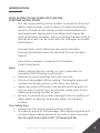
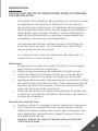
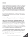
INTRODUCTION
READ INSTRUCTIONS COMPLETELY BEFORE
STARTING INSTALLATION
It is the responsibility of the installer to meet all code and
safety requirements, and to obtain all required building
permits.Thedeckandrailinginstallershoulddetermine
andimplementappropriateinstallaontechniquesfor
eachinstallaonsituaon.FortressRailingProductsandits
distributors shall not be held liable for improper or unsafe
installaons.
FortressPostsmustalwaysbesecuredtothedeck
framingandshouldneverbeaachedtoonlythedeck
boards.
PureViewI-SupportisrequiredforCanadian
CodeCompliance.
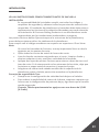
Note
WhencungFortressrailing,itisveryimportantto
completethefollowingatcutpoints:
• Removeallmetalshavingsfromthecutarea.
• Fileanysharpedgeslebycung.Thoroughlywipeand
removeanylings,grime,ordirtfromtherailing.
• ApplytwocoatsofFortresszincbasedtouch-uppaintto
thecutarea.Iftouchupisatrailends,allowpainttodry
beforeconnecngbrackettopost.
• Be sure to remove any metal shavings from the surface of
deck,pao,orbalconytopreventstainsonthedeck
surface.
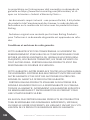
Torx Safety Tips
• Alwaysusethelowestspeedsengondrill.
• Toreducechanceofbitbreakage,startghteningwithdrill
onlowtorquesengandworkupunlscrewissecured.
Tip: Pre-drill holes with 3/16” [4.5mm] drill bit.

4
PURE VIEW: Al
13
HOME FULL GLASS PANEL INSTALLATION
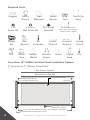
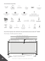
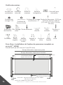
Required Tools
Goggles
Drill
Tape
Measurer
Level
Tool
Speed
Square
Touch-Up
Paint
Miter
Saw
T-25
Driver Bit
#2Phillips
Head Bit
Bit
Extender
5/16”[8mm]
Nut Driver Bit
DrillBits:1/16”,
3/16”,3/8”,5/8”[1.5mm,
4.5mm,9.5mm,16mm]
Pure View: Al
13
HOME Full Glass Panel Installaon Opons
Socket
Set
Pencil
Rubber
Mallet
Hex
Wrench
Crescent
Wrench
Socket
Wrench
PostCap
Straight Bracket Cup
Al
13
HOMEPostwithPostBaseCover
Straight Bracket Cap
Spring
Punch
Safety
Gloves
Liquid
Soap
Ratchet
Straps
2”[51mm]or3”[76mm]ProudPost
PureView:Al
13
HOMEFullGlassPanel68-1/2”[1740mm]
RoundAccentTopRail
FlatAccentTopRail
PureViewFullGlass
Al
13
HOMEVercalCable/
PureViewI-Support
File

5
PURE VIEW: Al
13
HOME FULL GLASS PANEL INSTALLATION
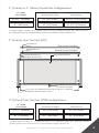
2”[51mm]OverThePost(OTP)
FlatATRLine
Splice
RoundATRLine
Splice
RoundAccentTopRail
FlatAccentTopRail
Straight Bracket Cup
Straight Bracket Cup
PureView:Al
13
HOMEFullGlassPanel68-1/2”[1740mm]
Al
13
HOMEPostwithPostBaseCover
PureViewFullGlass
Al
13
HOMEVercalCable/
PureViewI-Support
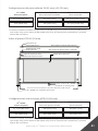
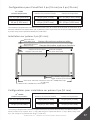
2”[51mm]or3”[76mm]ProudPostConguraons
*Installedheightsincludea3-1/2”[89mm]forthe32-1/2”[825.5mm]panel&2”[51mm]forthe
40”[1016mm] panel spacebetweendecksurfaceandboomedgeofboomrail.
Al
13
HOME
Panel Height
40”[1016mm]
Rail Panel
42”[1067mm]
InstalledPanelHeight
45-1/2”[1156mm]
RequiredPost
32-1/2”[826mm] 39-1/2”[1003.5mm]36”[914.5mm]
2”[51mm]OverThePost(OTP)Conguraons
Al
13
HOME
Panel Height
40”[1016mm]
Rail Panel
42”[1067mm]
InstalledPanelHeight
42”[1067mm]
RequiredPost
32-1/2”[826mm] 36”[914.5mm]36”[914.5mm]
*Installed heights include a 3-1/2” [89mm] for the 32-1/2” [825.5mm] panel & 2” [51mm] for the 40”
[1016mm] panel space between deck surface and bottom edge of bottom rail.

6
PURE VIEW: Al
13
HOME FULL GLASS PANEL INSTALLATION
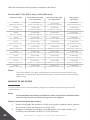
FullGlassPanelSizeChart
12.25”
[838mmx311mm]
18.25”
[838mmx464mm]
24.25”
[838mmx616mm]
31.25”
[838mmx794mm]
36.25”
[838mmx921mm]
41.25”
[838mmx1048mm]
46.25”
[838mmx1175mm]
51.25”
[838mmx1302mm]
56.25”
[838mmx1429mm]
61.25”
[838mmx1556mm]
18”to23”
[457mmto584mm]
24”to29”
[610mmto584mm]
30”to35”
[762mmto889mm]
37”to42”
[940mmto1067mm]
42”to47”
[1067mmto1194mm]
47”to52”
[1194mmto1321mm]
52”to57”
[1321mmto1448mm]
57”to62”
[1448mmto1575mm]
62”to67”
[1575mmto1702mm]
67”to72”
[1702mmto1829mm]
15”to20”
[381mmx508mm]
21”to26”
[533mmx660mm]
27”to32”
[686mmx813mm]
34”to39”
[868mmx991mm]
39”to44”
[991mmx1118mm]
44”to49”
[1118mmx1245mm]
49”to54”
[1245mmx1372mm]
54”to59”
[1372mmx1499mm]
59”to64”
[1499mmx1626mm]
64”to69”
[1626mmx1753mm]
Glass Widths 3” [76mm] Post
O.C. Spacing
Between Post
Spacing
32 1/2” [825.5mm] & 40” [1016mm] Panels
17”to22”
[432mmto559mm]
2” [51mm] Post
O.C. Spacing
23”to28”
[584mmto711mm]
29”to34”
[736.5mmto863.5mm]
36”to41”
[914.5mmto1041.5mm]
41”to46”
[1041.5mmto1168.5mm]
46”to51”
[1168.5mmto1295.5mm]
51”to56”
[1295.4mmto1422.4mm]
56”to61”
[1422.4mmto1549.4mm]
61”to66”
[1549.4mmto1676.4mm]
66”to71”
[1676.4mmto1803.4mm]
Note:
321/2”[825.5mm]panelusesa31-1/2”[800mm]tallpieceofglass
anda40”[1016mm]panelusesa39”[990.5mm]tallpieceofglass.
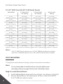
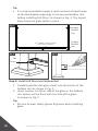
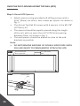
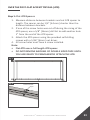
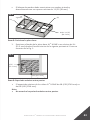
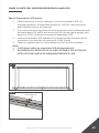
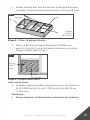
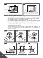
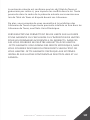
Step 1: Install Wood Blocks
1. InstallWoodBlocklevelwithtopofjoist.AsshowninFig.1(A)
2. SecureWoodBlocktoblockingonallfoursideswith#10X
3-1/2”[89mm]deckscrews.
POST MOUNTING
*IfusingFortressEvoluonFraming,contactFortressforinstrucons.
Note:
It’s recommended to install brackets into post before post
mounng. Reference page 9 for bracket Installaon steps.

7
PURE VIEW: Al
13
HOME FULL GLASS PANEL INSTALLATION
• WoodBlockmustbeconstructedwithtreateddimensional
lumberwithaminimumthicknessof11/2”[38mm].
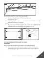
Step 3: Max Post Spacing
• 68-1/2”[1740mm]AL13HOMERailsmaximumpost
spacingis68-3/4”[1746mm].
Note:
• Do not exceed the maximum post spacing.
Fig. 1
#10x3-1/3”
[84.5mm]
(A)
(A)
Joist
Blocking
Step 2: Posion Base Plate
1. PosiontheedgeofAL
13
HOME base plate a minimum
of½”[12.5mm]fromtheinsideedgeofrimjoist.
AsshowninFig.1.
Fig. 1
1/2”[12.5mm]
1/2”
[12.5mm]

8
PURE VIEW: Al
13
HOME FULL GLASS PANEL INSTALLATION
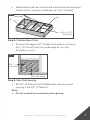
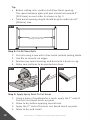
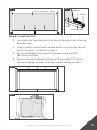
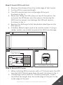
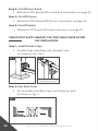
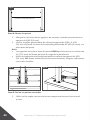
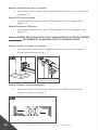
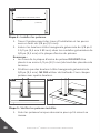
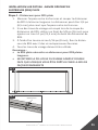
Step 5: Check Mounted Posts
1. Shimpostasneededtoensurepostislevel.
Step 4: Mount Posts
1. Markmounngholelocaonsandpre-drilla3/8”[9.5mm]
hole.
2. Insert3/8”x3-1/2”[9.5mmx89mm]HexHeadgalvanized
boltsthrough3/8”[9.5mm]galvanizedwasherandpost
baseplate.
Note:
• PostBasePlateholesMUSTbeposionedaminimum½”
[12.5mm]fromedgeofdeckboard.
• Useonly3/8”[9.5mm]HexHeadGalvanizedBolts.Lag
ScrewsshouldNOTbeused.Secureeachpostwithfourbolts.
Fig. 1
6’panelmaximumpostspacingis69-1/4”
[1759mm]
Fig. 1 Fig. 2
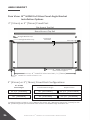
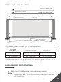
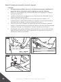
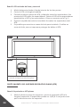
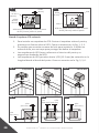
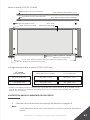
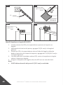
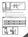
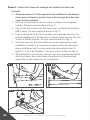
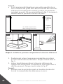
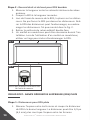
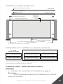
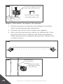
OTP and Proud Post: Max Post Spacing
• 8’ panel maximum post spacing is 93-7/8”.
• 6’ panel maximum post spacing is 69-7/8”.
Note: Do not exceed the maximum post spacing.
8’ Panel max post spacing 93-7/8”
6’ Panel max post spacing 69-7/8”
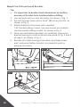
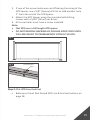
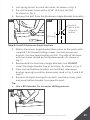
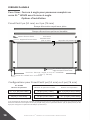
OTP and Proud Post: Measuring The Panel Opening Length
• Measure the distance of the panel opening.
• Measure from the back wall of the bracket to the back wall of the bracket on other post.
• Confirm that the measurements for the top brackets are the same as the bottom brackets.
Measure the panel opening
Not here
Measure from
back of bracket
Check measurement with top
3/12
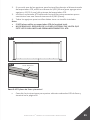
OTP and Proud Post: Max Post Spacing
• 8’ panel maximum post spacing is 93-7/8”.
• 6’ panel maximum post spacing is 69-7/8”.
Note: Do not exceed the maximum post spacing.
8’ Panel max post spacing 93-7/8”
6’ Panel max post spacing 69-7/8”
OTP and Proud Post: Measuring The Panel Opening Length
• Measure the distance of the panel opening.
• Measure from the back wall of the bracket to the back wall of the bracket on other post.
• Confirm that the measurements for the top brackets are the same as the bottom brackets.
Measure the panel opening
Not here
Measure from
back of bracket
Check measurement with top
3/12

9
PURE VIEW: Al
13
HOME FULL GLASS PANEL INSTALLATION
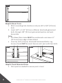
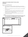
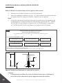
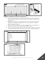
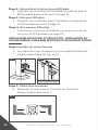
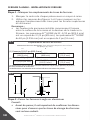
Step 1: Mark Bracket Hole Locaons
1. Markthecenterlineofeachpostwithapencil.
2. TakemeasurementsusedinFig.1and2tomarkboom
andtopbracketholelocaonsontoposts.
BRACKET INSTALLATION
Fig. 1
Bracket Hole Locaons
Pre-drill Dimensions: Pre-drillingwitha3/16”[4.5mm]drillbitisrequired
4”[101.5mm]
A*
3/8”[10mm]
B
3/8”[10mm]
35-3/16”[894mm]
C
411/4”[1048mm]
11/16”[17mm]
D
*DimensionAposionsboomedgeofrail(1) 3-1/2”[89mm]and(2) 2”[51mm]
abovedecksurface.
*DimensionAismeasuredfromtheboomsurfaceofpostbase.
2-1/2”[63.5mm]
11/16”[17mm]
32-1/2” [825.5mm] Panel
40” [1016mm] Panel
Fig. 2
B
C
B
A
B
D
(1)
(2)
Fig. 1
Fig. 2
Shim post as needed to
ensure post is level
Deck Board
RimJoist
Joist/Blocking
Wood Block
1/2”
[12.5
mm]
A

10
PURE VIEW: Al
13
HOME FULL GLASS PANEL INSTALLATION
Fig. 1 Fig. 2
Fig. 3
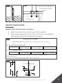
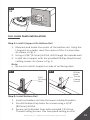
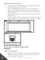
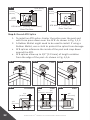
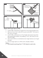
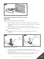
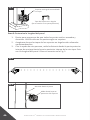
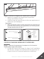
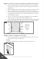
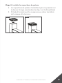
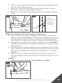
Step 2: Pre-Drill and Install Brackets
Tip:
• It’s important to double check dimensions to conrm
accuracy of bracket hole locaons before drilling.
1. UseSpringPunchtomarktheholes.AsshowninFig.1.
2. Pre-drillbracketholeswitha3/16”[89.5mm]drillbit.As
showninFig.2.
3. AachBrackettothepostswithsupplied
T-25thread-cungscrews.Usetwoscrewsperbracket.
Uselowspeedsengondrill.AsshowninFig.3.
4. Oncetopandboombracketsareinstalled,remeasure
bracketspacingtoconrmdimensionsusedinFig.2and3
ofstep1.AsshowninFig.4.
5. R e m o v e a l l m e t a l s h a v i n g s f r o m d e c k , p o s t b a s e c o v e r,
post,andpanelbeforebracketisscrewedtopostto
preventcorrosion.

11
PURE VIEW: Al
13
HOME FULL GLASS PANEL INSTALLATION
Fig. 4
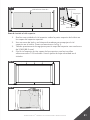
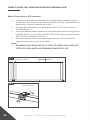
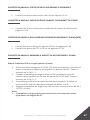
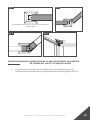
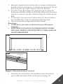
Step 3: Measure The Panel Opening Length
1. Measurethedistanceofthepanelopening.
AsshowninFig.1.
2. Conrmthatthemeasurementsforthetopbracketsarethe
sameastheboombrackets.
Note:
• Measure from the back wall of the bracket to the back wall
of the bracket on other post. As shown in Fig. 2.
CUTTING DOWN BOTTOM AND TOP RAILS
Step 1: Measure & Mark Rails Where Cuts Will Be Made
1. Takemeasurementsfoundonpage11,step3ofBracket
Installaonandmarktheselocaonswithapencilonthe
topandboomrail.
Fig. 1
Fig. 2
Measure the panel opening
Checkmeasurementwithtop
Do not
measure from
post
Measure
from back
of bracket

12
PURE VIEW: Al
13
HOME FULL GLASS PANEL INSTALLATION
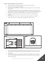
Fig. 1
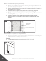
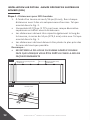
Step 2: Cut & Clean Rails
1. Cutrailsusingasawwithanetoothcarbidecungblade.
2. Useletosmoothcutedges.
3. Removeanymetalshavingsanddustwithabrushorrag.
4. Makesuresurfacestobepaintedareclean.
4”[101.5mm]max
spacing on each side
Step 3: Apply Spray Paint To Cut Areas
1. Usingapieceofcardboardasamask,applythe1
st
coat of
Fortresszincbasedtouch-uppaint.
2. Allowtodrybeforeapplyingsecondcoat.
3. Applythe2
nd
coatofFortresszincbasedtouch-uppaint.
4. Allowtodryandinstall.
Tip:
• Beforecungrails,conrmFullGlassPanelspacing.
Thespacebetweenglassandpostshouldnotexceed4”
[101.5mm]oneachside.AsshowninFig.1.
• Totalpanelopeninglengthshouldbeglasswidthplus8”
[203mm]max.
Fig. 1
Fig. 2
Fig. 3

13
PURE VIEW: Al
13
HOME FULL GLASS PANEL INSTALLATION
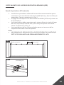
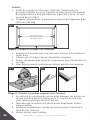
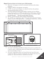
1. Measureandlocatethecenteroftheboomrail.Usingthe
I-Supportasaguide,markthecenterofthe2screwholes.
AsshowninFig.1.
2. Usinga3/16”[4.5mm]drillbit,drillthoughtheoutsidewall.
3. InstalltheI-SupportwiththeprovidedPhillipsHeadthread
cungscrews.AsshowninFig.2.
Note:
• BesuretoinstallI-Supportonsideofrailfacingdeck.
FULL GLASS PANEL INSTALLATION
Step 1: Install I-Support On Boom Rail
Fig. 1
2X
Fig. 1
3/16”
[4.5mm]
Hole
Fig. 2
Phillips
Head
Thread
Cung
Screws
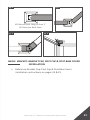
1. Install cut boomrailintothelowerinstalledbrackets.
2. Pre-drillBracket Cup holesforscrewsusinga3/16”
[89.5mm]drillbit.
3. SecurerailtoBracketCupswithprovidedT-25Drive
Thread-CungScrews.Uselowspeedsengondrill.
Step 2: Install Boom Rail

14
PURE VIEW: Al
13
HOME FULL GLASS PANEL INSTALLATION
Fig. 1
Straight
Bracket
Cup
Al
13
HOMEVercalCable/
PureViewI-Support
Straight
Bracket
Cup
Fig. 2
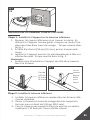
Step 3: Install Full Glass Into Boom Rail
1. Carefullyposionfullglasssheetintothecenterofthe
boomrail.AsshowninFig.1.
2. I n s e r t s p a c e r s o n e i t h e r s i d e o f t h e g l a s s i n t h e b o o m
rail.Spacerwillbeushwiththesideoftheglass.
AsshowninFig.2.
Tip:
• Besuretowearsafetygloves&glasseswhenhandling
glass.
Set
Screw
Tip:
• It is recommended to apply a small amount of liquid soap
totheblackgasketopeningsinthetopandboomrails
beforeinstallingFullGlass.AsshowninFig.3.TheLiquid
Soaphelpstheglassseleinplace.
Fig. 3

15
PURE VIEW: Al
13
HOME FULL GLASS PANEL INSTALLATION
Fig. 1
PureViewFullGlass
Fig. 2
Glass
Spacer
Step 4: Install Top Rail
1. CarefullyslipTopRailoverthetopoftheglassintothetop
BracketCups.
2. Usearubbermalletandawoodblocktodrivethetoprail
ontotheglass.AsshowninFig.2.
3. Pre-drillBracket Cup holesforscrewsusinga3/16”
[89.5mm]drillbit.
4. SecuretoprailtoBracketCupswithprovidedT-25Drive
Thread-CungScrews.Uselowspeedsengondrill.
BoomRail
Gasket
Fig. 1
TopRail
Fig. 2

16
PURE VIEW: Al
13
HOME FULL GLASS PANEL INSTALLATION
Step 5: Install Top Rail (Alternave)
1. CarefullyslipTopRailoverthetopoftheglassintothetop
BracketCups.
2. Carefully slip RatchetStraps over top rail and underneath
boomrail.
3. SlowlyclampeachStrapunlglassisfullyseatedintoprail.
AsshowninFig.1.
4. Pre-drillBracket Cup holesforscrewsusinga3/16”
[89.5mm]drillbit.
5. SecuretoprailtoBracketCupswithprovidedT-25Drive
Thread-CungScrews.Uselowspeedsengondrill.
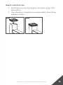
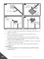
Step 6: Aach I-Support To Deck
1. FastenI-SupporttodecksurfacewiththesuppliedPhillips
HeadWoodScrew.
Tip:
• Pre-drillwitha1/16”[1.5mm]drillbit.
Fig. 1
Fig. 1
PureView
Full Glass
RatchetStraps

17
PURE VIEW: Al
13
HOME FULL GLASS PANEL INSTALLATION
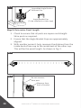
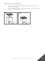
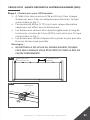
PROUD POST: ROUND ACCENT TOP RAIL (ATR)
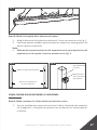
Step 1: Round ATR Spacers
1. AachSpacersusingprovidedself-drillingscrewswitha
5/16”[8mm]nutdriver,twoscrewsperspacer.Asshownin
Fig.2.
• TheAccentTopRailKitcomeswith6spacersinthe69.89”
[1775mm]kit.
• Thespacersshouldbeequallyspacedalongthelength
oftherail,withnomorethen14”[279.5mm]spacing
betweenthem.AsshowninFig.1.
• Theendspacersshouldbeplacedasclosetotheend
bracketsaspossible.
Note:
• DO NOT REMOVE BACKING OF DOUBLE SIDED TAPE UNTIL
YOU ARE READY TO PERMANENTLY ATTACH THE ATR.
Fig. 1
Double Sided
Tape
Fig. 2
14”[355.5mm]
Max
SpacerAached
NextToBracket

18
PURE VIEW: Al
13
HOME FULL GLASS PANEL INSTALLATION
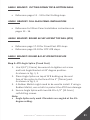
Step 2: Round ATR Line & End
1. Measurethedistancefromtheinsideedgeofthe2posts.
2. CuttheATRtomeasuredlength.
3. WhentestngtheATR,placeitontopofthespacers.
DonotpresstheATRdownoverthespacers.Removingthe
ATRfromthespacerscandamagetheATRandspacers.As
showninFig.2.
4. Removethebackingofallofthedouble-sidedtapeonthe
ATRspacers.
5. ARubberMalletmightneedtobeusedtoinstall.Ifusinga
RubberMallet,useaclothtoprotecttheATRfromdamage.
Fig. 1
PROUD POST: FLAT ACCENT TOP RAIL (ATR)
Step 1: Flat ATR Spacers
1. MeasuredistancebetweenbracketsandcutATRSpacerto
length.TheSpacercanbe1/4”[6.5mm]shorterthanthe
distancebetweenbrackets.
Fig. 2
ATRShouldNotGoPastThis
PointWhenTestFing

19
PURE VIEW: Al
13
HOME FULL GLASS PANEL INSTALLATION
1. MeasuredistancebetweenbracketsandcutATRSpacerto
length.TheSpacercanbe1/4”[6.5mm]shorterthanthe
distancebetweenbrackets.
2. Ifoneofthescrewholeswascutoduringthesizingofthe
ATRSpacer,usea5/8”[16mm]drillbittoaddanotherhole
1”fromtheendoftheATRSpacer.
3. AachtheATRSpacerusingtheprovidedself-drilling
screwswitha5/16”[8mm]nutdriver.
4. Allscrewholesmusthaveascrewinstalled.
Note:
• Flat ATR uses a full length ATR spacer.
• DO NOT REMOVE BACKING OF DOUBLE SIDED TAPE UNTIL
YOU ARE READY TO PERMANENTLY ATTACH THE ATR.
Fig. 1
Step 2: Flat ATR Line And End
• ReferenceProudPostRoundATRLine&Endinstruconson
page18.
Double Sided
Tape
Fig. 2

20
PURE VIEW: Al
13
HOME FULL GLASS PANEL INSTALLATION
OVER THE POST: ROUND ACCENT TOP RAIL (ATR)
Step 1: Round ATR Spacers
1. Aachspacersusingprovidedself-drillingscrewswitha
5/16”[8mm]nutdriver,twoscrewsperspacer.Asshownin
Fig.2.
• TheAccentTopRailKitcomeswith6spacersinthe69-7/8”
[1775mm]kit.
• Thespacersshouldbeequallyspacedalongthelength
oftherail,withnomorethen14”[279.5mm]spacing
betweenthem.AsshowninFig.1.
• Theendspacersshouldbeplacedasclosetotheend
bracketsaspossible.
Note:
• DO NOT REMOVE BACKING OF DOUBLE SIDED TAPE UNTIL
YOU ARE READY TO PERMANENTLY ATTACH THE ATR.
Double Sided
Tape
Fig. 2
Fig. 1
SpacerAached
NextToBracket
14”[279.5mm]
Max
La page charge ...
La page charge ...
La page charge ...
La page charge ...
La page charge ...
La page charge ...
La page charge ...
La page charge ...
La page charge ...
La page charge ...
La page charge ...
La page charge ...
La page charge ...
La page charge ...
La page charge ...
La page charge ...
La page charge ...
La page charge ...
La page charge ...
La page charge ...
La page charge ...
La page charge ...
La page charge ...
La page charge ...
La page charge ...
La page charge ...
La page charge ...
La page charge ...
La page charge ...
La page charge ...
La page charge ...
La page charge ...
La page charge ...
La page charge ...
La page charge ...
La page charge ...
La page charge ...
La page charge ...
La page charge ...
La page charge ...
La page charge ...
La page charge ...
La page charge ...
La page charge ...
La page charge ...
La page charge ...
La page charge ...
La page charge ...
La page charge ...
La page charge ...
La page charge ...
La page charge ...
La page charge ...
La page charge ...
La page charge ...
La page charge ...
La page charge ...
La page charge ...
La page charge ...
La page charge ...
La page charge ...
La page charge ...
La page charge ...
La page charge ...
La page charge ...
La page charge ...
La page charge ...
La page charge ...
La page charge ...
La page charge ...
La page charge ...
La page charge ...
La page charge ...
La page charge ...
La page charge ...
La page charge ...
La page charge ...
La page charge ...
La page charge ...
La page charge ...
La page charge ...
La page charge ...
La page charge ...
La page charge ...
La page charge ...
La page charge ...
La page charge ...
La page charge ...
La page charge ...
La page charge ...
-
 1
1
-
 2
2
-
 3
3
-
 4
4
-
 5
5
-
 6
6
-
 7
7
-
 8
8
-
 9
9
-
 10
10
-
 11
11
-
 12
12
-
 13
13
-
 14
14
-
 15
15
-
 16
16
-
 17
17
-
 18
18
-
 19
19
-
 20
20
-
 21
21
-
 22
22
-
 23
23
-
 24
24
-
 25
25
-
 26
26
-
 27
27
-
 28
28
-
 29
29
-
 30
30
-
 31
31
-
 32
32
-
 33
33
-
 34
34
-
 35
35
-
 36
36
-
 37
37
-
 38
38
-
 39
39
-
 40
40
-
 41
41
-
 42
42
-
 43
43
-
 44
44
-
 45
45
-
 46
46
-
 47
47
-
 48
48
-
 49
49
-
 50
50
-
 51
51
-
 52
52
-
 53
53
-
 54
54
-
 55
55
-
 56
56
-
 57
57
-
 58
58
-
 59
59
-
 60
60
-
 61
61
-
 62
62
-
 63
63
-
 64
64
-
 65
65
-
 66
66
-
 67
67
-
 68
68
-
 69
69
-
 70
70
-
 71
71
-
 72
72
-
 73
73
-
 74
74
-
 75
75
-
 76
76
-
 77
77
-
 78
78
-
 79
79
-
 80
80
-
 81
81
-
 82
82
-
 83
83
-
 84
84
-
 85
85
-
 86
86
-
 87
87
-
 88
88
-
 89
89
-
 90
90
-
 91
91
-
 92
92
-
 93
93
-
 94
94
-
 95
95
-
 96
96
-
 97
97
-
 98
98
-
 99
99
-
 100
100
-
 101
101
-
 102
102
-
 103
103
-
 104
104
-
 105
105
-
 106
106
-
 107
107
-
 108
108
-
 109
109
-
 110
110


Fortress Technologies PURE VIEW FULL GLASS PANEL AL13 HOME Installation Instructions Manual
- Taper
- Installation Instructions Manual
dans d''autres langues
Documents connexes
Autres documents
-
Deckorators Contemporary Cable Continuous Top Rail Bracket Guide d'installation
-
-
-
Claire Deco I-28-40102-SN Mode d'emploi
-
Art Decor I-04-0072-WF/VB Mode d'emploi
-
Ryobi GDM1234 Le manuel du propriétaire
-
Feiss POSTBASE-SBL Mode d'emploi
-
Velleman VTBAL13 Manuel utilisateur
-
 ADEUNIS ARF 868 MR Mode d'emploi
-
 ADEUNIS ARF868 LP/LR/MR/ULR Mode d'emploi

