
INTELLIBRITE® 5G White Pool and Spa LED Light Installation and User’s Guide
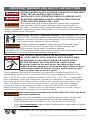
IMPORTANT SAFETY INSTRUCTIONS
READ AND FOLLOW ALL INSTRUCTIONS
SAVE THESE INSTRUCTIONS
INSTALLATION AND
USER’S GUIDE
INTELLIBRITE® 5G
WHITE AND COLOR POOL AND SPA LIGHTS

II
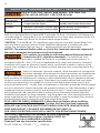
Technical Support: Phone: (800) 831-7133 - Fax: (800) 284-4151
Web site: www.pentair.com
Contents
IMPORTANT WARNING AND SAFETY INSTRUCTIONS............................. iii-iv
IntelliBrite 5G Pool and Spa Lights Overview .................................................... 1
Operating IntelliBrite Pool and Spa lights using a wall switch (12 VAC) ............ 1
Using an External Transformer for Multiple IntelliBrite 12 VAC Lights ................1
Powering on IntelliBrite 5G Lights .................................................................... 2
Selecting a light show mode or fixed color (Color Lights) ................................. 2
Using an IntelliBrite Color Light Controller ........................................................ 2
Replacing the IntelliBrite 5G Pool and Spa Light Fixture
(in an existing pool/after electrical requirements are met) .............................. 3/5
IntelliBrite 5G Pool and Spa Light Fixture Installation
(new pool construction - GFCI Installation Requirements (USA) .................... 6/7
IntelliBrite 5G Pool and Spa Light Fixture Installation
(new pool construction (Canada) ..................................................................... 7
Junction Box/GFCI Installation Requirements (Canada) .................................. 8
Installing the IntelliBrite 5G Pool and Spa Light Fixture
(after electrical requirements are met) ............................................................. 9
IntelliBrite 5G Pool Light (12 V) Fuse Harness Replacement Overview .......... 11
Replacing the IntelliBrite 5G Pool Light Circuit Board Assy (existing pool).......12
Installing the IntelliBrite Light Assembly, new gasket/Uni-tension Wire Clamp .15
Wide and Narrow Angle Lens Adjustment/Part Numbers ............................19/20
Replacing the IntelliBrite Spa Light Fixture (existing pool) .............................. 21
IntelliBrite 5G Spa Light Replacement Kit Part Numbers ................................ 25
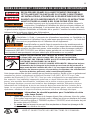
Always install a new Uni-Tension Wire Clamp assembly
and Lens Gasket (see page 19), when reassembling the light
assembly. Failure to do so may permit water to leak into the assembly which
could cause; (a) an electrical hazard resulting in death or serious injury to pool
users, installer, or others due to electrical shock, or (b) breakage of the lamp
or lens, which likewise could result in serious injury to pool user, installers, or
bystanders, or in damage to property.
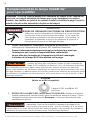
Before Installing luminaries read the following:
THE INTELLIBRITE 5G LED POOL LIGHT AND SPA
LIGHT CANNOT BE USED ON A DIMMER CIRCUIT.
USING A DIMMER SWITCH WILL RESULT IN PERMANENT
DAMAGE TO THE LIGHT.
P/N 620278 Rev C - 2/2019
INTELLIBRITE® 5G Pool and Spa Lights Installation and User’s Guide
FOR 12 VAC LUMINARIES: ALWAYS USE A SEPARATE STEP DOWN
TRANSFORMER TO POWER LUMINARIES. SEE DIAGRAM ON PAGE 7. Note:
Connect all three wires to the corresponding circuit wires in the Junction
Box (black wire to power, white wire to common, and green wire to ground).
12 VAC LUMINARIES SPECIFICATION: 50/60 Hz. REPLACE ANY CRACKED
PROTECTIVE SHIELD (CRACKED LENS) WITH NEW LENS AND GASKET.

INTELLIBRITE® 5G Pool and Spa Lights Installation and User’s Guide INTELLIBRITE® 5G Pool and Spa Lights Installation and User’s Guide
III
Most states and local codes regulate the construction, installation,
and operation of public pools and spas, and the construction of
residential pools and spas. It is important to comply with these codes, many of which
directly regulate the installation and use of this product. Consult your local building and
health codes for more information.
SERIOUS BODILY INJURY OR DEATH CAN RESULT IF THIS LIGHT
IS NOT INSTALLED AND USED CORRECTLY.
INSTALLERS, POOL OPERATORS AND POOL OWNERS MUST
READ THESE WARNINGS AND ALL INSTRUCTIONS BEFORE
USING THE POOL AND/OR SPA LIGHT.
Before installing this product, read and follow all warning notices
and instructions in this Guide. Failure to follow warnings and
instructions can result in severe injury, death, or property damage.
Call (800) 831-7133 for additional free copies of these instructions. Please refer to www.
pentairpool.com for more information related to this products.
IMPORTANT NOTICE - Attention Installer: This Installation and User’s
Guide (“Guide”) contains important information about the installation, operation
and safe use of this underwater pool and spa light. This Guide should be given
to the owner and/or operator of this equipment.
IMPORTANT WARNING AND SAFETY INSTRUCTIONS
BEFORE WORKING ON POOL AND SPA LIGHTS always
disconnect power to the pool and/or spa lights at the circuit
breaker from the light before servicing the light. Failure to do so
could result in death or serious injury to service person, pool
users or others due to electric shock.
RISK OF ELECTRICAL SHOCK OR ELECTROCUTION:
This underwater light must be installed by a licensed or certified electrician or a
qualified pool professional in accordance with the current National Electrical Code
(NEC), NFPA 70 or the Canadian Electrical Code (CEC), CSA C22.1. All applicable
local installation codes and ordinances must also be adhered to. Improper installation
will create an electrical hazard which could result in death or serious injury to pool
users, installers or others due to electrical shock, and may also cause damage
to property. Always disconnect the power to the pool light at the circuit breaker
before servicing the light. Failure to do so could result in death or serious injury to
serviceman, pool users or others due to electrical shock.
Important Safety Information for Pentair Water Pool and Spa Niche
and Light Installation
• All Niche and Light installations must conform with all codes. If local codes
mandate a cord seal, use Pentair Water Pool and Spa plastic niches
(P/N 79206600 and P/N 79206700) and Cord Seal Kit (P/N 670044).
• Under no circumstances replace lights by splicing wire under water or behind
niche.
THE INTELLIBRITE® POOL AND SPA LIGHT REQUIRE HIGH
VOLTAGE WHICH CAN SHOCK, BURN, OR CAUSE DEATH.
Before Installing luminaries read the following:
READ AND FOLLOW ALL INSTRUCTIONS IN THIS MANUAL.

IV
For countries in compliance with International Electromechnical
Commission (IEC) regulatory standards: The light fixture must
be installed by a licensed or certified electrician or a qualified pool service person, in
accordance with IEC 364-7-702 and all applicable local codes and ordinance. Improper
installation will create an electrical hazard, which could result in death or serious injury
to pool user, installer or other due to electrical shock and may also cause damage to the
property.
IMPORTANT WARNING AND SAFETY INSTRUCTIONS
RISK OF ELECTRIC SHOCK AND INJURY. USE ONLY THE
(*) Note: Wet-niche luminaires complying with requirements for both uses may bare
both the Listed Wet-Niche Submersible Luminaires UL Mark. A luminaire not bearing the
corresponding UL Listing Mark is not considered by UL to have been produced under UL’s
Listing and Follow-Up Service for the associated usage location.
CAUTION - The IntelliBrite® 5G Light fixture must only be used with Pentair Water Pool
and Spa fixture housings (niches). If the IntelliBrite light fixture is installed into other
niches, the installation will not carry U.L. approval and will void all warranties.
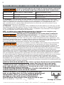
Salt is an inherently corrosive material. While the levels of salt required
for proper operation of an electronic chlorine generator are relatively low
when compared to sea water and other salt solutions, placing any amount of salt in your
pool increases the likelihood of corrosion or other deterioration of pool equipment and any
surfaces used in and around your pool. Metal parts and certain natural and man-made
surfaces are particularly susceptible to corrosion and deterioration when used in and
around salt water pools. Pentair does not represent or otherwise guarantee that the proper
use of an electronic chlorine generator will prevent corrosion or other deterioration of pool
equipment and any surfaces used in and around your pool. Consult your experienced
pool professional, who should be able to advise you on the proper material selection,
installation techniques for those materials, and the proper use, care and maintenance of
those materials for your specific pool type and location in order to minimize the corrosion
and deterioration that is inherent in and around salt water pools.
INSTALLATION METHOD SPECIFIED BELOW.
NOTICE: The external flexible cable or cord of this luminaire cannot be replaced; if
the cord is damaged, the luminaire shall be destroyed.
REPLACE ANY CRACKED PROTECTIVE SHIELD (CRACKED LENS) WITH NEW
LENS AND GASKET. FOR MORE INFORMATION SEE PAGE 11.
FOR LIGHT OPERATION, ONLY USE A SAFETY ISOLATION TRANSFORMER.
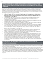
POOL AND SPA FIXED LUMINARIES: Follow these guidelines when installing,
replacing or repairing Pentair Aquatic Systems Pool and Spa fixed luminaries:
Location of Pentair Water Pool and Spa Fountain Required Installation Method
Luminaire Use Fixture* (P/N 560001 and P/N 560000)
Swimming Pool Wet-Niche Swimming Pool Fixture Housing (Forming Shell) ONLY.
and Spa (or Spa) Luminaire (Light) DO NOT USE Fountain Fixture Stand.
Fountain Wet-Niche Submersible Luminaire (Light) Fixture Housing (Forming Shell) or
swimming Pool (or Spa) Luminair (Light) Fountain Fixture Stand
CAUTION! Luminaires not suitable for direct mounting
on normally flammable surfaces (suitable ONLY for
mounting on non-combustible surfaces.
Surface Mount
Fixed pool and spa luminaries specification:
12 VAC 50/60 Hz - 120VAC ,50/60 Hz.

INTELLIBRITE® 5G Pool and Spa Lights Installation and User’s Guide INTELLIBRITE® 5G Pool and Spa Lights Installation and User’s Guide
1
IntelliBrite® 5G Pool and Spa Lights Overview
Operating Pool and Spa Lights Using a Wall Switch (12 VAC)
IntelliBrite 5G pool and spa lights can be manually controlled using a standard wall-mount
light switch. Multiple IntelliBrite lights can be connected via a junction box to a single
switch so that all lights can be switched on and off together. IntelliBrite lights can also be
automatically controlled via Pentair IntelliTouch®, EasyTouch® and SunTouch® Control
Systems. Note: Multiple IntelliBrite 5G pool/spa lights can also be controlled using
the IntelliBrite Controller, for more information see page 2.
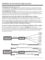
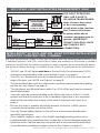
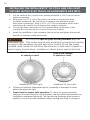
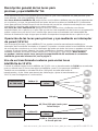
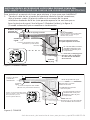
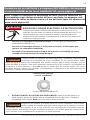
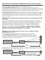
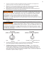
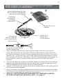
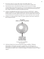
Using an External Transformer for Multiple IntelliBrite 12 VAC Lights
When using multiple IntelliBrite 12 VAC lights on a 300 Watt transformer, it is
recommended that no more than three IntelliBrite pool lights and one IntelliBrite Spa light
be used. It is also recommended not to exceed 100 ft (30.5 m) of total cable run between
the transformer and light. Note: For long cable lengths, set the transformer to 14 VAC
(see diagrams below).
300 Watt
Transformer J Box
12 Gauge
(Minimum)
300 Watt
Transformer J Box
12 Gauge
(minimum)
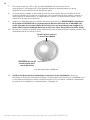
This manual describes how to install the IntelliBrite 5G white and color pool light and the
IntelliBrite 5G white and color spa light.
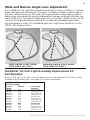
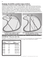
The IntelliBrite 5G white light provides a brilliant white light for a spectacular effect in
your pool and spa. The IntelliBrite 5G white light lens geometry (pool light only) provides
a choice between two light beam shapes; wider coverage with less intensity, or narrower
coverage with more intensity.
The IntelliBrite 5G color light provides brilliant vivid multi-colors with spectacular effects
for your pool and spa. Choose one of the seven pre-programmed color light shows or
select one of the five fixed colors to create virtually endless range of dramatic underwater
lighting effects for a spectacular effect in your pool and spa.
100 ft. (30.5 m)
150 ft. (45.8 m) max. for spa
200 ft. (61 m) max. for pool light

2
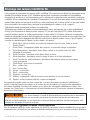
Powering on IntelliBrite® 5G Color Lights
When the IntelliBrite light is powered on, a momentarily white light will illuminate,
followed by the previously selected color. Note: If power to the light is off for more than
five seconds, the last color show mode or fixed color that was saved will be displayed.
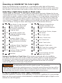
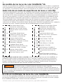
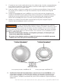
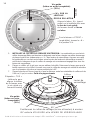
Selecting a light show mode or fixed color
Switch power on to the light. A white light will momentarily illuminate, followed by the pre-
viously selected color. To select a color show mode (1-7) or fixed color (8-12), turn the wall
switch off/on a specific number of times. Each number (1-12) shown below corresponds to
the number of times to power-cycle the switch to activate a color light show or fixed color.
For details about saving color effects while in “show” modes, see “Hold” and “Recall” fea-
ture on page 3. Example: To select California Sunset Mode; turn the light on, then turn off
and on six times. During the off/on switching process, no illumination will occur,
Saving a Color Mode or Fixed Color: When power is switched off to the IntelliBrite
color lights, the last color show mode or fixed color will be saved. The next time the light
is powered on, the previously saved color show mode or fixed color will be displayed.
For example, while in “Party Mode” switch the light off. Wait more than 10 seconds,
switch the light back on to resume “Party Mode.”
During the off/on switching process, before the selected color is displayed,
no illumination will occur for a brief second. This operating
mode is normal during the switching process. During this period the pool and spa will be
dark and precautions should be taken to avoid unforeseen accidents. Failure to observe
this warning may result in serious injury or death to pool and spa users.
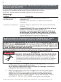
1 SAm Mode: Cycles through
white, magenta, blue and
green colors (emulates
the Pentair SAm® color
changing light).
2 Party Mode: Rapid color
changing building energy
and excitement.
3 Romance Mode: Slow
color transitions creating a
mesmerizing and calming
effect.
4 Caribbean Mode: Transitions
between a variety of blues
and greens.
5 American Mode: Patriotic
red, white and blue
transition.
6 California Sunset Mode:
Dramatic transitions of
orange, red and magenta
tones.
7 Royal Mode: Richer, deeper
color tones.
8 Blue: Fixed color.
9 Green: Fixed color.
10 Red: Fixed color.
11 White: Fixed color.
12 Magenta: Fixed color.
13 Hold: Save the current color
effect during a color light
show.
14 Recall: Activate the last
saved color effect.
Number of times to cycle power (1-5)
Number of times to cycle power (6-14)
Using the IntelliBrite Controller (sold separately, P/N 600054), IntelliBrite 5G color pool/spa
lights can all be synchronized so that individual or multiple IntelliBrite lights all lights can be
switched on and off together.
Using an IntelliBrite Color Light Controller

INTELLIBRITE® 5G Pool and Spa Lights Installation and User’s Guide INTELLIBRITE® 5G Pool and Spa Lights Installation and User’s Guide
3
Risk of Electrical Shock or Electrocution!
This underwater light must be installed by a licensed or certified electrician or
a qualified pool professional in accordance with the National Electrical Code
and all applicable local codes and ordinances. Improper installation will create
an electrical hazard which could result in death or serious injury to pool users,
installers or others due to electrical shock, and may also cause damage to
property. Always disconnect the power to the pool light at the circuit breaker
before servicing the light. Failure to do so could result in death or serious injury
to service person, pool users or others due to electrical shock.
Replacing the IntelliBrite® 5G Pool and Spa
Light Fixture (in an existing pool or spa)
Verify that the pool and spa meets the requirements of the current National Electrical
Code and all local codes and ordinances. A licensed or certified electrician must install
the electrical system to meet or exceed those requirements before the underwater light
is installed. Some of the requirements of the National Electrical Code which the pool’s
electrical system must meet are as follows:
• 120 VAC pool/spa lights must have a Ground Fault Circuit Interrupter (GFCI), with an
appropriately rated circuit breaker. 12 VAC pool/spa/lights do not require a GFCI. See
Figure 1, page 7 for details.
• The Junction Box: For 12 volt models only, the low voltage step-down transformer
shall be located at least 8 in (20.3 cm) above the maximum water line and at least
4 in (10.2 cm) above the ground level or pool deck whichever provides the greater
elevation. The junction box shall be no less than 4 ft (1.22 m) from the inside wall of
the pool, unless separated from the pool by a solid fence, wall or other permanent
barrier. See Figure 3 on page 9.
• Bond the niche-fixture housing to all other metallic items within 5 ft (1.53 m) of the
pool, using a No. 8 AWG bond wire. The Bond connection is located at the rear of the
niche, see Figure 3 on page 9.
• The wet niche is properly installed so the top edge of the underwater light’s lens is at
least 18 inches (45.7 cm) below the surface of the water in the pool, see Figure 3 on
page 9. Also, the face ring PILOT SCREW must be at the 12 o’clock position.
• If non-metallic conduit is used, a No. 8 AWG bonding/grounding wire must be
installed through the conduit from the Junction Box to the bonding/grounding lug
inside the niche. Seal the wire/lug connection with a listed sealant to protect the
connection from possible pool water corrosion. See Figure 3 on page 9.
• To be certain that the pool’s electrical system meets all applicable requirements, the
electrician should also consult the local building department. Note: Use only Pentair
wet niches to insure proper bonding and grounding connections.
Switch power on to the light. A white light will momentarily illuminate, followed by the pre-
viously selected color. To select a color show mode (1-7) or fixed color (8-12), turn the wall
switch off/on a specific number of times. Each number (1-12) shown below corresponds to
the number of times to power-cycle the switch to activate a color light show or fixed color.
For details about saving color effects while in “show” modes, see “Hold” and “Recall” fea-
ture on page 3. Example: To select California Sunset Mode; turn the light on, then turn off
and on six times. During the off/on switching process, no illumination will occur,
During the off/on switching process, before the selected color is displayed,
no illumination will occur for a brief second. This operating
mode is normal during the switching process. During this period the pool and spa will be
dark and precautions should be taken to avoid unforeseen accidents. Failure to observe
this warning may result in serious injury or death to pool and spa users.
Using the IntelliBrite Controller (sold separately, P/N 600054), IntelliBrite 5G color pool/spa
lights can all be synchronized so that individual or multiple IntelliBrite lights all lights can be
switched on and off together.
To select a color light show mode or fixed color mode, rotate the dial so that it points
to the desired selection.
Hold and Recall Feature: When IntelliBrite color lights are powered on, the
previously selected color will be displayed, unless the HOLD or RECALL feature was
previously enabled.
Hold button/LED: Press this button (LED on) to capture and save a color effect while
displaying one of the light show modes. When the button is pressed, the LED will be
on, indicating that the color effect is captured.
Recall Button/LED: Use this button (LED on) to activate the last saved color effect.
When the button is pressed, the LED will be on, indicating that the color effect is being
displayed.

4
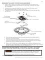
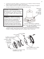
The following removal and installation instructions describe how to remove and
install the IntelliBrite pool and spa light assembly. Also use these instructions
after completing the following light replacement procedure:
Note: For IntelliBrite Spa Light, Face Ring, Uni-Tension Wire Clamp, Gasket and
Lens Removal and Installation instructions, see page 21.
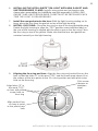
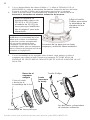
2. To remove light fixture assembly from the pool. Remove the special
bronze (or stainless steel) pilot screw at top of face ring. Remove the
IntelliBrite light assembly from the niche and place it on the deck.
3. Cut the cord about 12 in (30.5 cm) from the back of the light
assembly.
4. Remove Junction Box cover, disconnect the light fixture wires, and
pull the cord through the conduit. Tip: Before pulling the cord, tape
the new cord to the existing cord, This might make it easier to
feed the new cord through the conduit (see the following step).
5. Feed the new light fixture cord through the conduit from the niche
to the Junction Box. Note: Depending on the length of the conduit,
special tools may be required to pull the cord through the conduit.
6. Leave at least 4 ft (1.2 m) of cord to coil around the light fixture; see
Figure 3 on page 9. This allows the light to be serviced on the deck
after the pool is filled with water.
7. Cut the cord at the Junction Box, leaving at least 6 in (1.27 cm) of
cord to make the connections.
8. Strip 6 in (15.2 cm) of the outer cord jacket from the cord to expose
the three insulated conductors. Be careful not to damage the insulation
on the three inner conductors). Strip a 1/2 in (1.27 cm) of insulation
off the three conductors. Be careful not to damage the copper
conductor.
Failure to bring the pool or spa’s electrical system up to code requirements
before installing the underwater light will create an electrical hazard which
could result in death or serious injury to pool users, installers, or others due
to electrical shock, and may also cause damage to property.
1. Switch off main electrical switch or circuit breaker, and the
switch which operates the IntelliBrite underwater light.
• Do not service the light while in the pool water. Service the
light on the deck.
Replacing the IntelliBrite®
5G Pool and Spa Light Fixture
(After Electrical Requirements Are Met)

INTELLIBRITE® 5G Pool and Spa Lights Installation and User’s Guide INTELLIBRITE® 5G Pool and Spa Lights Installation and User’s Guide
5
Use only the special pilot screw provided with this
underwater light. This screw mounts and electrically grounds the housing
securely to the mounting ring and wet niche. Failure to use the screw
provided could create an electrical hazard which could result in death or
serious injury to pool users, installers or others due to electrical shock.
13. Final check for proper IntelliBrite light operation: Switch on
the main switch or circuit breaker to the system, and the switch
that operates the IntelliBrite underwater light itself. The light should
illuminate when power is applied. If not recheck the installation
steps starting with Step 1 (page 4).
9. Connect the three light wires to the corresponding light circuit wires
in the Junction Box. Connect the black wire to power, white wire to
common, and the green wire to ground.
10. Secure the Junction Box cover.
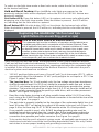
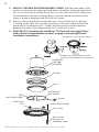
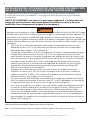
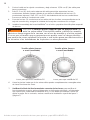
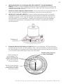
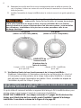
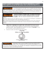
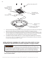
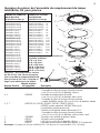
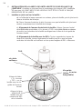
11. Install the IntelliBrite® light assembly into the pool niche. Be sure to
insert the TAB on the lower part of the face ring into the niche SLOT
(located on the lower part of the niche). This is important to secure
the lower part of the light assembly onto the niche before tightening
the pilot screw.
12. Carefully tighten the special bronze (or stainless steel) pilot screw to
secure the upper part of the light assembly onto the niche.
IntelliBrite 5G Pool Light IntelliBrite 5G Spa Light
Face ring TAB
(insert into
niche slot)
Pilot screw (bronze
or stainless steel) Pilot screw (bronze
or stainless steel)

6
The following describes how to install the IntelliBrite® Pool Light fixture and
the IntelliBrite Spa Light fixture. Read page 4 before starting the installation
procedure.
Be sure that the pool or spa meets the requirements of
the current National Electrical Code (N.E.C.) Article 680
and all local codes and ordinances. A licensed or certified electrician must
install the electrical system to meet or exceed those requirements before
the underwater light is installed. Some of the requirements of the National
Electrical Code which the pool’s electrical system must meet are as follows:
BEFORE STARTING: The following steps 1-13 (page 4-5) describe the tasks
that must be completed by the electrician before the IntelliBrite light fixture
is installed. See Figure 1 diagram on page 7.
Note: To be certain that the pool or spa electrical system meets all applicable
requirements, the electrician should also consult the local building department.
Note: Use only Pentair wet niches to insure proper bonding and grounding connections.
• 120 VAC pool/spa lights must be connected to a Ground Fault Circuit Interrupter
(GFCI), with an appropriately rated circuit breaker. See Figure 1, page 7 for
details.
• The Junction Box (or, for 12 volt models, the low voltage transformer) shall be
located at least 8 in (20.3 cm) above the maximum water line and at least four 4
in (10.2 cm) above the ground level or pool deck whichever provides the greater
elevation. The junction box shall be no less than 4 ft (1.22 m) from the inside
wall of the pool, unless separated from the pool by a solid fence, wall or other
permanent barrier. See Figure 3 on page 9.
• Bond the niche-fixture housing to all other metallic items within 5 ft (1.53 m) of the
pool, using a No. 8 AWG bond wire. The Bond connection is located at the rear of
the niche, see Figure 3 on page 9.
• The wet niche is properly installed so the top edge of the underwater light’s lens
is at least 18 in (45.7 cm) below the surface of the water in the pool, see Figure 3
on page 9. Also, the face ring PILOT SCREW must be at the 12 o’clock position.
• If non-metallic conduit is used, a No. 8 AWG bonding/grounding wire must be
installed through the conduit from the Junction Box to the bonding/grounding lug
inside the niche. Seal the wire/lug connection with a listed sealant to protect the
connection from possible pool water corrosion. See Figure 3 on page 9.
INTELLIBRITE® 5G POOL AND SPA LIGHT FIXTURE INSTALLATION
(NEW POOL CONSTRUCTION - USA)

INTELLIBRITE® 5G Pool and Spa Lights Installation and User’s Guide INTELLIBRITE® 5G Pool and Spa Lights Installation and User’s Guide
7
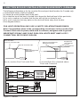
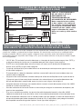
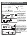
12 VAC
120 VAC
12 VAC LUMINARIES (NO GFCI REQUIRED)
SAFETY ISOLATING
TRANSFORMER
120 V to 12 V
STEP DOWN
TRANSFORMER
(100 W or 300 W)
120 VAC LUMINARIES (GFCI REQUIRED)
Figure 1, USA
FOR LIGHT OPERATION,
ONLY USE A SAFETY
ISOLATION TRANSFORMER.
Note: Connect three wires
to the corresponding
circuit wires in the Junction
Box. Connect: Black wire
to power, white wire to
common, and green wire to
ground. IMPORTANT!
120 VAC POOL/SPA LIGHTS
MUST HAVE A GFCI
CONNECTION.
GFCI 12 VAC LIGHT INSTALLATION REQUIREMENTS (USA)
Be sure the electrical system of your pool conforms with the following requirements of the
Canadian Electrical Code (CE), and all local codes and ordinances. A licensed or certified
electrician must install the electrical system to meet or exceed those requirements before
the light and (fixture-housing) is installed. Some of the CE requirements are listed below.
• 120 VAC and 12 VAC lights must have a Ground Fault Circuit Interrupter (GFCI),
and have an appropriately rated circuit breaker. Figure 2 on page 8.
• The GFCI or a transformer must be located at least 3 m (10 ft) or more from the
edge of the pool, see *NOTE and Figure 2 on page 8.
• The junction/deck box must be sealed to the conduit to prevent water from getting
into the box, see Figure 2 on page 8.
• The light fixture and all metal items within 3 m (10 ft) of the pool must be properly
electrically bonded.
• The niche must be properly installed so the pilot screw hole is at the 12 o’clock
position and that the center line of the Underwater Light’s lens is at a maximum
depth of 600 mm below the surface of the water in the pool, see Figure 4 on
page 9.
• Be sure the niche is properly electrically bonded via the No. 6 AWG ground
connector located at the rear of the niche.
• Use only Pentair lighting fixtures in this niche to ensure proper bonding and
grounding connections.
• If non-metallic conduit is used, a No. 8 AWG bonding/grounding wire must be
installed through the conduit from the Junction Box to the bonding/grounding lug
inside the niche. Seal the wire/lug connection with a listed sealant to protect the
connection from possible pool water corrosion. See Figure 4 on page 9.
INTELLIBRITE® 5G POOL AND SPA LIGHT FIXTURE INSTALLATION
(NEW POOL CONSTRUCTION - CANADA)

8
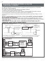
The following information is for the Junction Box and pool deck location for Canada only.
Junction/Deck boxes shall be installed:
(a) above the normal water level of the pool;
(b) so that the top of the box is located at or above the finished level of the pool deck;
(c) in such a manner or location that the box will not be an obstacle; and
(d) in such a manner that any water on the deck will drain away from the box
(See diagram below).
FOR LIGHT OPERATION, ONLY USE A SAFETY ISOLATION TRANSFORMER.
Note: Connect three wires to the corresponding circuit wires in the Junction Box.
Connect: Black wire to power, white wire to common, and green wire to ground.
IMPORTANT! 120 VAC AND 12 VAC POOL/SPA LIGHTS MUST HAVE A GFCI
CONNECTION. SEE FIGURE 2 BELOW.
JUNCTION BOX/GFCI INSTALLATION REQUIREMENTS (CANADA)
Deck water drains
away from Junction/Deck Box
Approved Junction/Deck Box
Water level
below Junction/Deck Box
Approved Junction/Deck Box
elevated and protected
Diving Board or
other equipment
to protect
Junction/Deck Box
Top of Junction Box Flush with Deck Junction/Desk Box elevated above
Deck and Protected
Figure 2, Canada.
12 VAC
120 VAC
12 VAC LUMINARIES (GFCI REQUIRED FOR CANADA)
SAFETY ISOLATING
TRANSFORMER
120 V to 12 V
STEP DOWN
TRANSFORMER
(100 W or 300 W)
120 VAC LUMINARIES (GFCI REQUIRED FOR CANADA)

INTELLIBRITE® 5G Pool and Spa Lights Installation and User’s Guide INTELLIBRITE® 5G Pool and Spa Lights Installation and User’s Guide
9
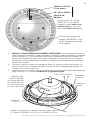
1. Switch off main electrical switch or circuit breaker, and the switch which
operates the IntelliBrite underwater light.
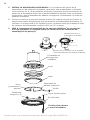
Route light cable through conduit to Junction Box, leaving at least 4 ft (1.22 m) of
cable at the light fixture to coil around the light (this allows the light to be serviced
on the deck after the pool is filled with water). See Figure 3 (USA), and Figure 4,
(Canada) below.
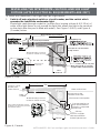
Figure 3, USA.
To install the IntelliBrite® Pool Light and Spa Light fixture:
204 mm
406 mm
292 mm
Coil 1.22 m of light
cable around fixture
for deck light removal .
Concrete must be cut
back around Niche to
allow for a compacted
plaster seal.
Rigid
Conduit
Junction/Deck Box must have a water tight bushing.
To GFCI, Circuit
Breaker and
Power Source.
GFCI and/or Transformer must be
located 3 m or more from pool wall.
(See *NOTE above.)
600 mm max. to the
centerline of the Lens.
Water surface level
Pilot Screw at 12 o'clock position
#6 AWG Bonding Connector
(located on outside of niche)
3 m
INSTALLING THE INTELLIBRITE® 5G POOL AND SPA LIGHT
FIXTURE (AFTER ELECTRICAL REQUIREMENTS ARE MET)
Figure 4, Canada.
18 in (42.72 cm) minimum
to top of lens
4 in (10.2 cm) minimum
48 in (121.92 cm) minimum
16 in
40.64 cm
11.50 in (29.21 cm) min.
8 in (20.32 cm)
Wrap around 48 in (122 cm)
of light cable around fixture
Pilot screw at
12 O’Clock
#8 AWG Bonding Connector
(located on outside of niche)

10
2. Cut the cable at the Junction Box, leaving at least 6 in (15.3 cm) of cord to
make connections.
3. Strip back 6 in (15.3 cm) of the outer cord jacket to expose the three
insulated conductors (be careful not to damage the insulation on the
three inner conductors). Strip a 1/2 in (1.27 cm) of insulation off the three
conductors. Be careful not to damage the copper conductor.
4. Connect all three conductors to the corresponding circuit wires in the
Junction Box and secure the Junction Box cover in place.
INSTALLING THE INTELLIBRITE® 5G POOL AND SPA LIGHT
FIXTURE (AFTER ELECTRICAL REQUIREMENTS ARE MET)
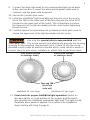
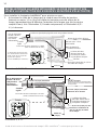
5. Install the IntelliBrite® Light assembly into the niche and tighten the special
bronze (or stainless steel) pilot screw.
Use only the special pilot screw provided with this
underwater light. This screw mounts and electrically grounds the housing
securely to the mounting ring and wet niche. Failure to use the screw
provided could create an electrical hazard which could result in death or
serious injury to pool users, installers or others due to electrical shock.
6. Fill the pool until the underwater light is completely submerged in water
before operating the light.
7. Final check for proper light operation: To check for proper operation,
switch on the main switch or circuit breaker, and the switch that operates the
IntelliBrite underwater light itself. The light should illuminate when power is
applied. If not recheck the installation steps starting with Step 1 on page 4.
IntelliBrite 5G Spa Light
IntelliBrite 5G Pool Light
Pilot screw (bronze
or stainless steel) Pilot screw (bronze
or stainless steel)

INTELLIBRITE® 5G Pool and Spa Lights Installation and User’s Guide INTELLIBRITE® 5G Pool and Spa Lights Installation and User’s Guide
11
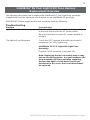
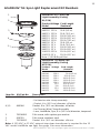
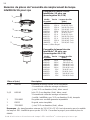
Troubleshooting
Problem Cause/Action
Light does not function properly Check the light wiring connection to the junction box
at the pool side and to the AC power switch.
Be sure that there is proper AC power applied to
the light.
The light will not illuminate. Check the GFCI ground fault wiring and reset if
necessary. For 120 V lights only.
IntellliBrite 5G 12 V Light with Light Fuse
Assembly
Replace FUSE assembly (see page 14):
Note: Replacing the fuse assembly may or may
not resolve this problem. In some instances the
fuse assembly will blow, and after replacing
the fuse the light’s circuit board is still not
functional. In this case, the circuit board must
be replaced.
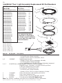
IntelliBrite® 5G Pool Light (12V) Fuse Harness
Replacement Overview
The following describes how to replace the IntelliBrite 5G Pool Light fuse assembly
(if applicable) and the light main circuit board for the IntelliBrite 5G pool light.
IMPORTANT! Before replacing the fuse assembly note the following:

12
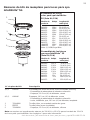
Always install a new lens gasket (P/N 620400Z) and Uni-Tension
Wire Clamp (P/N 600095) whenever disassembling the IntelliBrite
light assembly. Failure to do so may permit water to leak into the assembly which
could cause:
(a) an electrical hazard resulting in death or serious injury to pool users, installers,
or others due to electrical shock, or
(b) breakage of the lens, which likewise could result in serious injury to pool users,
installers, or bystanders, or in damage to property.
REPLACING THE INTELLIBRITE POOL LIGHT CIRCUIT BOARD
ASSEMBLY (IN AN EXISTING POOL)
1. Turn off main electrical switch or circuit breaker, as well as the switch which
operates the IntelliBrite light itself. Note: DO NOT service the light while in
the pool water. Service the light on the deck.
2. Before starting be sure that you have a new lens gasket (P/N 620400Z),
Uni-Tension Wire Clamp (P/N 600095) and a IntelliBrite 5G pool light circuit
board assembly (P/N 619875Z - 300w, P/N 619916Z-400W, P/N 619917Z-
500w) - P/N 619818Z (Color) ready to install.
Removal and Installation of IntelliBrite 5G Light Circuit Board
D A N G E R !
RISK OF ELECTRICAL SHOCK OR ELECTROCUTION
Always disconnect power to the pool light at the circuit breaker
before servicing the light. Failure to do so could result in death
or serious injury to installer, service person, pool users, or
others due to electrical shock.
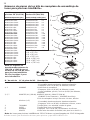
When replacing the IntelliBrite Pool Circuit Board, the Unit-Tension
Wire Clamp (P/N 600095), (Gasket (P/N 620400Z) or Gasket and Lens
(619864Z) MUST ALSO BE REPLACED - SEE PAGE 20 FOR PART
NUMBERS.
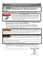
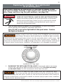
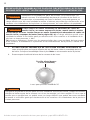
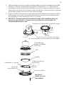
3. REMOVING THE INTELLIBRITE 5G POOL LIGHT ASSEMBLY: Remove
the pilot screw at top of face ring, remove the light assembly from the niche.
Place the assembly on the deck. Note: It is not necessary to drain down the
pool.
4. Unwind the cord from the base of the light housing.
Replace the light circuit board assembly with the same type and
wattage. Failure to replace the light circuit board assembly with
the same type will damage the light assembly and may cause an electrical hazard
resulting in death or serious injury to pool users, installers, or others due to
electrical shock, and may also cause damage to property.
IntelliBrite 5G Pool Light
Pilot screw (bronze
or stainless steel)

INTELLIBRITE® 5G Pool and Spa Lights Installation and User’s Guide INTELLIBRITE® 5G Pool and Spa Lights Installation and User’s Guide
13
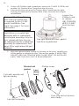
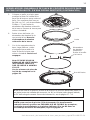
5. Place a cloth on the ground to
protect the lens. Turn the light
over so the lens is resting on
the cloth. Using a 1/4 in (0.64
cm) nut driver and a #3 Phillips
screwdriver, remove the nut from
the Uni-Tension Wire Clamp.
Place the nut aside for
reinstallation.
6. Remove the face ring and
wire clamp from the light
housing. Discard the
Uni-Tension Wire Clamp.
7. With the light resting on
its base, carefully pry off
the gasket to remove the
lens. Set the lens aside for
installation later. Discard
the gasket.
Note: A NEW LENS
GASKET (P/N 620400Z)
AND UNI-TENSION WIRE
CLAMP MUST BE USED
EACH TIME THE LIGHT IS
REASSEMBLED.
See page 20 for
Replacement Kit part
numbers.
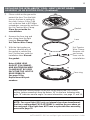
REPLACING THE INTELLIBRITE® POOL LIGHT CIRCUIT BOARD
ASSEMBLY (IN AN EXISTING POOL) (Continued)
Uni-Tension
Wire Clamp:
Remove nut
and screw,
Save nut for
reinstallation.
Face ring
Lens
Note: Note the current position of the lens at the pilot screw (12 o’clock)
position, before removing it from the fixture. “W” on the lens indicates wide
angle, “N” indicates narrow angle. For more information, see page 17 and 19.
Gasket
NOTE: For a pool light (12 V only, no internal step-down transformer)
that has a replacement FUSE ASSEMBLY, continue the procedure on
the next page. If the light does NOT have a replacable fuse assembly,
proceed to page 15.

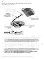
14
Light housing
with circuit
board
Circuit board
terminals
Replaceable
fuse
harness
assembly
Fuse harness
(press down
to release)
Carefully remove
connector plug from
circuit board terminals
Replaceable fuse harness assembly
1. Using your fingers, carefully disconnect each fuse connector plug from the
circuit board terminals. Carefully lift each connector plug upward, with small
side-to-side movements while holding the circuit board terminals with a flat
screw driver. Then gradually disconnect the connector plug from the terminal.
Note: To avoid permanent damage to the circuit board, be sure not to pull the
terminals off the surface of the circuit board.
2. Once the fuse connector plugs are removed from the circuit board terminals,
separate the fuse assembly from the light wire harness by pressing down on the
fuse release lever, then gently pull apart.
REPLACING THE FUSE HARNESS ASSEMBLY (FOR 12 V LIGHTS ONLY)
3. Insert the new fuse harness connector into the light cable harness plug and snap
together.
4. Using your fingers to carefully connect each fuse connector plug onto the circuit
board terminals. Be sure not to press down to hard on the connector, this can
damage the terminal connections on the circuit board.
5. Continue with “INSTALLING THE INTELLIBRITE® 5G POOL LIGHT
ASSEMBLY WITH NEW GASKET AND UNI-TENSION WIRE CLAMP”
on page 15.

INTELLIBRITE® 5G Pool and Spa Lights Installation and User’s Guide INTELLIBRITE® 5G Pool and Spa Lights Installation and User’s Guide
15
INSTALLING THE INTELLIBRITE® POOL LIGHT ASSEMBLY WITH NEW
GASKET AND UNI-TENSION WIRE CLAMP (See step 1 on next page)
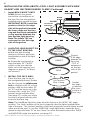
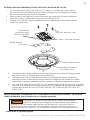
4. Place the two new thermal strips (provided) over the circuit board studs in
the base of the light housing.
5. Place the light circuit board over the base studs and seat the circuit board
on top of the thermal strips. Be sure the two connecting wires are not caught
between the housing and the edge of the circuit board.
6. Using a 1/4 in (0.64 cm) nut driver, tighten each of the four retaining nuts to a
torque value of 6.0 (minimum) to 8.0 (maximum) in-lbs to secure the circuit board.
DO NOT OVERTIGHTEN THE CIRCUIT BOARD NUTS.
Be sure to install ALL of the four retaining nuts. These nuts
ensure proper electrical ground. Failure to install all of the retaining nuts
could create an electrical hazard which could result in death or serious
injury to pool users, installers or others due to electrical shock.
Continue on next page.
Retaining nut (4x)
Light housing
Thermal
strip (2x)
Circuit board
connector plugs
Circuit board
Circuit board
stud (4x)
1. Using a 1/4 in (0.64 cm) nut driver, carefully remove the four retainer nuts
from the light assembly (see illustration on next page). Place the nuts aside
for reinstallation.
2. Unplug the two connector plugs from the circuit board. Lift up the circuit
board and remove it from the light housing base.
3. Carefully lift off the old thermal strips from the base of the light housing base
and discard.
REMOVING THE LIGHT CIRCUIT BOARD ASSEMBLY

INTELLIBRITE® 5G Pool and Spa Lights Installation and User’s Guide
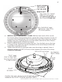
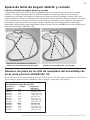
Note: The IntelliBrite light lens ships from the factory in the ‘WIDE’ (W) angle
position. The “wide” position of the lens is typically used for lights located either
side of the pool. The “narrow” position of the lens is typically used for lights located
either end of the pool. To use the “NARROW” angle light beam, rotate the lens/
gasket to align the letter “N” on lens. Note: For more information about the “WIDE”
and NARROW angle lens position, see page 19.
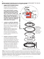
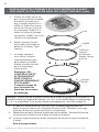
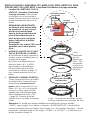
INSTALLING THE INTELLIBRITE® POOL LIGHT ASSEMBLY WITH NEW
GASKET AND UNI-TENSION WIRE CLAMP (Continued)
Uni-Tension
Wire ClampGasket
flat edge
is towards
the inner
surface of
face ring
LENS
Gasket
(Flat edge
towards the
face ring
- TOP is
embossed
on the top
side of the
gasket)
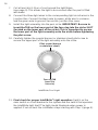
1. Install NEW GASKET ONTO
LENS: Stretch the gasket
around the circumference of
the lens. Be sure the gasket is
installed evenly around the lens.
IMPORTANT NOTE: Install the
gasket so that the flat edge
side of the gasket is towards
the inner surface of the face
ring and the Black embedded
o-ring must be between the
lens and the light housing.
Note: The letters TOP are
embossed on the flat edge
side of the gasket.
2. ALIGN THE LENS/GASKET ON
TO THE LIGHT HOUSING:
a) With the light housing
resting on its base, place the
lens/gasket on top of the light
housing.
b) Rotate the lens/gasket to
align the letter “W” (“WIDE”
angle) on the lens with the
brass nut in the housing (see
diagram on page 17 for brass
nut location).
3. INSTALL THE FACE RING:
Place the face ring on top of
the lens/gasket/housing. Rotate
the face ring so the pilot screw
hole is aligned in the 12 o’clock
position, with the lens letter “W”
(or “N”) and the brass nut in the
housing. Also, verify the “TOP”
position arrow indicator label
(see page 17) on the rear of the
housing is aligned with the pilot
screw on the face ring.
GASKET
FACE RING
LENS
LIGHT HOUSING
INSDIE OF
FACE RING
UNI-TENSION
WIRE CLAMP
BLACK
O-RING
GASKET
LIGHT
HOUSING
16
La page est en cours de chargement...
La page est en cours de chargement...
La page est en cours de chargement...
La page est en cours de chargement...
La page est en cours de chargement...
La page est en cours de chargement...
La page est en cours de chargement...
La page est en cours de chargement...
La page est en cours de chargement...
La page est en cours de chargement...
La page est en cours de chargement...
La page est en cours de chargement...
La page est en cours de chargement...
La page est en cours de chargement...
La page est en cours de chargement...
La page est en cours de chargement...
La page est en cours de chargement...
La page est en cours de chargement...
La page est en cours de chargement...
La page est en cours de chargement...
La page est en cours de chargement...
La page est en cours de chargement...
La page est en cours de chargement...
La page est en cours de chargement...
La page est en cours de chargement...
La page est en cours de chargement...
La page est en cours de chargement...
La page est en cours de chargement...
La page est en cours de chargement...
La page est en cours de chargement...
La page est en cours de chargement...
La page est en cours de chargement...
La page est en cours de chargement...
La page est en cours de chargement...
La page est en cours de chargement...
La page est en cours de chargement...
La page est en cours de chargement...
La page est en cours de chargement...
La page est en cours de chargement...
La page est en cours de chargement...
La page est en cours de chargement...
La page est en cours de chargement...
La page est en cours de chargement...
La page est en cours de chargement...
La page est en cours de chargement...
La page est en cours de chargement...
La page est en cours de chargement...
La page est en cours de chargement...
La page est en cours de chargement...
La page est en cours de chargement...
La page est en cours de chargement...
La page est en cours de chargement...
La page est en cours de chargement...
La page est en cours de chargement...
La page est en cours de chargement...
La page est en cours de chargement...
La page est en cours de chargement...
La page est en cours de chargement...
La page est en cours de chargement...
La page est en cours de chargement...
La page est en cours de chargement...
La page est en cours de chargement...
La page est en cours de chargement...
La page est en cours de chargement...
La page est en cours de chargement...
La page est en cours de chargement...
La page est en cours de chargement...
La page est en cours de chargement...
La page est en cours de chargement...
La page est en cours de chargement...
La page est en cours de chargement...
La page est en cours de chargement...
La page est en cours de chargement...
La page est en cours de chargement...
La page est en cours de chargement...
La page est en cours de chargement...
La page est en cours de chargement...
-
 1
1
-
 2
2
-
 3
3
-
 4
4
-
 5
5
-
 6
6
-
 7
7
-
 8
8
-
 9
9
-
 10
10
-
 11
11
-
 12
12
-
 13
13
-
 14
14
-
 15
15
-
 16
16
-
 17
17
-
 18
18
-
 19
19
-
 20
20
-
 21
21
-
 22
22
-
 23
23
-
 24
24
-
 25
25
-
 26
26
-
 27
27
-
 28
28
-
 29
29
-
 30
30
-
 31
31
-
 32
32
-
 33
33
-
 34
34
-
 35
35
-
 36
36
-
 37
37
-
 38
38
-
 39
39
-
 40
40
-
 41
41
-
 42
42
-
 43
43
-
 44
44
-
 45
45
-
 46
46
-
 47
47
-
 48
48
-
 49
49
-
 50
50
-
 51
51
-
 52
52
-
 53
53
-
 54
54
-
 55
55
-
 56
56
-
 57
57
-
 58
58
-
 59
59
-
 60
60
-
 61
61
-
 62
62
-
 63
63
-
 64
64
-
 65
65
-
 66
66
-
 67
67
-
 68
68
-
 69
69
-
 70
70
-
 71
71
-
 72
72
-
 73
73
-
 74
74
-
 75
75
-
 76
76
-
 77
77
-
 78
78
-
 79
79
-
 80
80
-
 81
81
-
 82
82
-
 83
83
-
 84
84
-
 85
85
-
 86
86
-
 87
87
-
 88
88
-
 89
89
-
 90
90
-
 91
91
-
 92
92
-
 93
93
-
 94
94
-
 95
95
-
 96
96
-
 97
97


Pentair Intellibrite 5G White and Color Lights Le manuel du propriétaire
- Taper
- Le manuel du propriétaire
- Ce manuel convient également à
dans d''autres langues
Documents connexes
-
Pentair GloBrite Color Changing LED Lights Le manuel du propriétaire
-
-
-
-
Pentair SPABRITE Guide d'installation
-
-
Pentair COLOR SYNC Mode d'emploi
-
Pentair 618031 Mode d'emploi
-
-
Autres documents
-
Pentair Pool MICROBRITE Mode d'emploi
-
Pentair Pool Products Amerlite Le manuel du propriétaire
-
-
 NOVOLUX LIGHTING 955A-L0102A Manuel utilisateur
-
Stonco Tall wall pack LED Install Instructions
-
 Dopo lighting 539A-G21X1A Manuel utilisateur
-
 Dopo lighting 916A-L0103K Mode d'emploi
-
NOVOLUX LIGHTING 947A-L3104A Mode d'emploi
-
Jandy AquaLink RS Control Systems Manuel utilisateur
-
CMP Brilliant Wonders® LED Light Mode d'emploi


