Garland 36ER33-88 Mode d'emploi
- Catégorie
- Cuisinières
- Taper
- Mode d'emploi

Part # 1844082 (11/03/08) Page 1
Users are cautioned that maintenance and repairs must be performed by a Garland authorized service agent
using genuine Garland replacement parts. Garland will have no obligation with respect to any product that has been
improperly installed, adjusted, operated or not maintained in accordance with national and local codes or installation
instructions provided with the product, or any product that has its serial number defaced, obliterated or removed,
or which has been modified or repaired using unauthorized parts or by unauthorized service agents.
For a list of authorized service agents, please refer to the Garland web site at http://www.garland-group.com.
The information contained herein, (including design and parts specifications), may be superseded and is subject
to change without notice.
GARLAND COMMERCIAL INDUSTRIES, LLC
185 East South Street
Freeland, Pennsylvania 18224
Phone: (570) 636-1000
Fax: (570) 636-3903
GARLAND COMMERCIAL RANGES, LTD.
1177 Kamato Road, Mississauga, Ontario L4W 1X4
CANADA
Phone: 905-624-0260
Fax: 905-624-5669
Enodis
U
Swallow e
Telephone
:
Fax: 081-8
4
Part # 18144082 (11/03/08) © 2005 Garland Commercial Industries, LLC
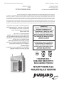
FOR YOUR SAFETY:
DO NOT STORE OR USE GASOLINE
OR OTHER FLAMMABLE VAPORS OR
LIQUIDS IN THE VICINITY OF
THIS OR ANY OTHER
APPLIANCE
WARNING:
IMPROPER INSTALLATION, ADJUSTMENT,
ALTERATION, SERVICE OR MAINTENANCE
CAN CAUSE PROPERTY DAMAGE, INJURY,
OR DEATH. READ THE INSTALLATION,
OPERATING AND MAINTENANCE
INSTRUCTIONS THOROUGHLY
BEFORE INSTALLING OR
SERVICING THIS EQUIPMENT
PLEASE READ ALL SECTIONS OF THIS MANUAL
AND RETAIN FOR FUTURE REFERENCE.
THIS PRODUCT HAS BEEN CERTIFIED AS
COMMERCIAL COOKING EQUIPMENT AND
MUST BE INSTALLED BY PROFESSIONAL
PERSONNEL AS SPECIFIED.
IN THE COMMONWEALTH OF MASSACHUSETTS
THIS PRODUCT MUST BE INSTALLED BY A
LICENSED PLUMBER OR GAS FITTER. APPROVAL
NUMBER: G-1-07-05-28
For Your Safety:
Post in a prominent location, instructions to be
followed in the event the user smells gas. This
information shall be obtained by consulting
your local gas supplier.
INSTALLATION AND
OPERATION MANUAL
THE “MASTER” HALF-SIZE
GAS CONVECTION OVEN

Part # 1844082 (11/03/08)Page 2
IMPORTANT INFORMATION
WARNING:
This product contains chemicals known to the state of California to cause cancer and/or birth defects
or other reproductive harm. Installation and servicing of this product could expose you to airborne
particles of glass wool/ceramic fibers. Inhalation of airborne particles of glass wool/ceramic fibers
is known to the state of California to cause cancer. Operation of this product could expose you to
carbon monoxide if not adjusted properly. Inhalation of carbon monoxide is known to the state of
California to cause birth defects or other reproductive harm.
Keep appliance area free and clear of combustibles.

Part # 1844082 (11/03/08) Page 3
TABLE OF CONTENTS
IMPORTANT INFORMATION..........................................2
DIMENSIONS AND SPECIFICATIONS ..................................4
INSTALLATION......................................................5
Rating Plate ......................................................................5
Clearances .......................................................................5
Gas Connections .................................................................5
Ovens equipped with Casters ....................................................6
Electrical Connection ............................................................6
Ventilation and Air Supply ........................................................6
Assembly ........................................................................7
Double Deck Units ...............................................................7
OPERATION.........................................................8
Testing & Lighting ...............................................................8
Master 200 Solid State Control With Electromechanical Timer ......................8
In O Mode..................................................................8
Start Up......................................................................8
Fan Speed ...................................................................9
Cool Down...................................................................9
Temperature .................................................................9
Timer........................................................................9
PERFORMANCE RECOMMENDATIONS ................................9
COOKING GUIDE...................................................10
PROBLEMS/SOLUTIONS ............................................11
MAINTENANCE AND CLEANING.....................................11
Break-In Period .................................................................11
Exterior Cleaning ...............................................................11
Interior Cleaning ................................................................12
Fan Area Maintenance ..........................................................12
Motor Care .....................................................................12

Part # 1844082 (11/03/08)Page 4
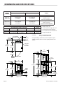
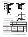
DIMENSIONS AND SPECIFICATIONS
6"
[152mm]
32"
[813mm]
32"
[813mm]
1"
[25mm]
71"
[1803mm]
26"
[660mm]
DOUBLE DECK
FRONT VIEW
9-1/2"
[241mm]
32"
[813mm]
14-3/4"
[375mm]
32"
[813mm]
26"
[660mm]
32"
[813mm]
1"
[25mm]
6
[152mm]
39"
[991mm]
SINGLE DECK
FRONT VIEW
9-1/2"
[241mm]
REAR
GAS
INLET
29-15/32"
[749mm]
16-3/4"
[425mm]
8-21/32"
[220mm]
38-1/8"
[968mm]
2-3/4"
[70mm]
4"
[102mm]
TOP VIEW
3/4" N.P.T.
[19mm]
GAS INLET
6' ELECTRIC
CORD OUTLET
1" N.P.T.
GAS INLET
MODEL
NUMBER
Manifold Operating Pressure
ELECTRICAL
SUPPLY
NATURAL GAS PROPANE
4.0” WC, (10 mbar) 10.0” WC, (24.9 mbar) 120 VOLTS
MCO-G-5L
MCO-G-5R
60,000 BTU/hr
(17.6 kW/hr)
60,000 BTU/hr
(17.6 kW/hr)
Single Phase
60Hz, 6.0 Amps
6-ft. Line Cord Supplied
MCO-G-25L
MCO-G-25R
120,000 BTU/hr
(35.2 kW/hr)
120,000 BTU/hr
(35.2 kW/hr)
Single Phase
60Hz / 6.0 Amps
(2) 6-ft. Line Cords Supplied
INTERIOR DIMENSIONS, (PER DECK) SHIP WT.
MODEL # WIDTH HEIGHT DEPTH lbs. / kg
MCO-G-5 14.25” (362mm) 20” (508mm) 20.75” (527mm) 435/195
MCO-G-25 14.25” (362mm) 20” (508mm) 20.75”(527mm) 870/390
Models shown are:
L, with controls on right side and
the door hinged on left side; R
has controls on left side with door
hinged on right side.
Gas Inlet: One @ 3/4" NPT Single Deck
One @ 1" NPT Double Deck
Gas Input Ratings shown here are for installations up to
2,000 ft. (610mm) above sea level. Specify altitudes over
2,000 ft.

Part # 1844082 (11/03/08) Page 5
INSTALLATION
The importance of the proper installation of commercial
Gas cooking Equipment cannot be over stressed. Proper
performance of the equipment is dependent, in great part,
on the compliance of the installation with the manufacturer’s
specications. Installation must conform to local codes or,
in the absence of local codes, with the National Fuel Code,
ANSI Z223.1, Natural Gas Installation Code, CAN/CGA-B149.1
or the Propane Installation Code, CAN/CGA-B149.2, as
applicable.
Before assembly and connection, check gas supply.
A. The type of gas for which the unit is equipped is stamp on
the date plate located behind lower front panel. Connect
a unit stamped “NAT” only to natural gas; connect a unit
stamped “PRO” only to propane gas.
B. If it is a new installation, have gas authorities check meter
size and piping to assure that the unit is supplied with
sucient amount of gas pressure required to operate the
unit.
C. If it is additional or replacement equipment, have gas
authorities check pressure to make certain that existing
meter and piping will supply fuel at the unit with not
more than 1/2” water column pressure drop.
NOTE: When checking pressure be sure that all other
equipment on the same gas line is on. An internal pressure
regulator is supplied with GARLAND Convection Ovens.
Regulator is preset to deliver gas at pressure shown on the
rating plate.
The appliance and its individual shut-o valve must be
disconnected from the gas supply piping system during any
pressure testing of that system at test pressures in excess of
1/2 PSI (3.45kPa.).
The appliance must be isolated from the gas supply piping
system by closing its individual manual
shut-o valve during any pressure testing of the gas supply
piping system at test pressures equal to or less than
1/2 PSI (3.45 kPa).
Rating Plate
When corresponding with the factory or your local
authorized factory service center regarding service problems
or replacement parts, be sure to refer to the particular unit
by the correct model number (including the prex and sux
letters and numbers) and the warranty serial number. The
rating plate located behind the lower front panel contains
this information.
We suggest installation, maintenance and repairs should be
performed by your local authorized service agency listed in
your information manual pamphlet.
In the event you have any questions concerning the
installation, use, care or service of the product, write or call
our Product Service Department.
This product must be installed by professional personnel as
specied. Garland/U.S. Range products are not approved or
authorized for home or residential use, but are intended for
commercial applications only. Garland / U.S. Range will not
provide service, warranty, maintenance or support of any
kind other than in commercial applications.
Clearances
Combustible and Non-Combustible Wall Clearance:
Side: 1.0” (25mm)
Rear: 1.0” (25mm)
NOTE: Adequate clearance must be provided for servicing
and proper operation.
Gas Connections
A readily accessible gas shut o valve of an approved type
must be installed in the gas supply line upstream of the
unit’s pressure regulator. A pipe joint compound resistant to
liqueed petroleum gases should be used on all pipe joints.
The American National Standards Institute mandates the
use of a pressure regulator on all commercial cooking
equipment. Garland provides an approved internal pressure
regulator with each unit.
When piping the gas supply for a double stack unit, note that
the supply inlet is 1” NPT as opposed to 3/4” for the single
deck. An undersized gas supply line may restrict the ow of
gas and aect the performance of the appliance. If there are
other gas appliances supplied by the same supply line, the
line must be sized to carry the combined volume without
suering a pressure drop of more than 1/2” water column at
the manifold of each appliance on the line at full rate.

Part # 1844082 (11/03/08)Page 6
Ovens equipped with Casters
A. For an appliance equipped with casters, the installation
shall be made with a connector that complies with the
Standard for Connectors for Movable Gas Appliances,
ANSI Z21.69 /CSA 6.16, and a quick-disconnect device
that complies with the Standard for Quick-Disconnect
Devices for Use With Gas Fuel, ANSI Z21.41 / CSA 6.9,
and adequate means must be provided to limit the
movement of the appliance without depending on
the connector and the quick-disconnect device or its
associated piping to limit the appliance movement and
the location(s) where the restraining means may be
attached to the appliance shall be specied.
B. The front casters of the unit are equipped with brakes
to limit the movement of the oven without depending
on the connector and any quick-disconnect device or its
associated piping to limit the appliance movement.
C. The restraint can be attached to the unit near the gas
inlet. If the restraint is disconnected, be sure to reconnect
the restraint after the oven has been returned to its
originally installed position.
Electrical Connection
A separate 10-amp service must be provided for each oven
section. For 115V usage, a cord and plug is provided. The
appliance, when installed, must be electrically grounded
in accordance with local codes, or in the absence of local
codes, with the National electrical code, ANSI/NFPA 70, or the
Canadian Electrical code, CSA C22.2, as applicable.
The appliance is equipped with a three prong (grounding)
plug for your protection against shock hazard and should
be plugged directly into a properly grounded three-prong
receptacle. Do not cut or remove the grounding prong from
this plug.
A wiring diagram is attached to the rear of each oven.
Ventilation and Air Supply
The appliance must be installed in a location in which the
facilities for ventilation permit satisfactory combustion of
gas and proper circulation of air within the available space.
If conning conditions do not allow for normal inltration of
necessary air, outside air must be introduced.
All gas burners and pilots need sucient air to operate. Large
objects placed in front of the unit may inhibit the ow of air
into the front of the oven and result in poor performance.
A good ventilation system is necessary for proper
performance. All Garland Convection Ovens must be
vented by installation under a powered vent canopy, or by
connection to a properly congured direct ue.
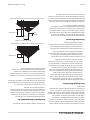
The ue opening is located at the top rear of the oven. Care
should be taken to avoid blockage of this opening.
When the installation of a canopy type exhaust hood is
impossible the oven may be direct vented. Before direct
venting check your local codes on ventilation.
It is recommended that a downdraft diverter be installed in
the direct ue. The parts necessary for proper installation of
direct ueing are available from Garland.
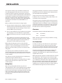
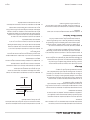
If a horizontal run must be used it should rise not less than
1/4” (6.25mm) for each linear foot of run. The ue should rise
2’ (60cm) to 3’ (90cm) above the roof line or 2’ (60cm) to 3’
(90cm) above any portion of a building within a horizontal
distance of 10 feet (3 meters).
Termination Less than 10 feet (3 meters from ridge
Less than 10 feet (3 meters)
2' (60cm) Min.
3' (90cm) Min.
T
ermination More than 10 feet (3 meters) from ridge
More than 10' (3 meters)
3' (90cm) Min.
INSTALLATION Continued

Part # 1844082 (11/03/08) Page 7
INSTALLATION Continued
Assembly
All units are equipped with N.S.F. approved legs. These
legs must be installed to provide a minimum 6” (153mm)
clearance between the oor and the bottom of the unit in
order to meet national Sanitation Foundation requirements.
A. To install the legs, raise the front of the unit and block
it. Insert the two front legs into the conical leg retainers.
Repeat at the rear.
B. Level the unit by placing a carpenter’s-type level on one
of the oven racks, and adjust each leg by turning its “foot”
to raise or lower the height of the leg. The bottom of each
“foot” is hexagonal in shape so that a wrench may be
used.
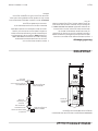
Double Deck Units
A. Install legs as above to the bottom unit.
B. Remove the combustion chamber from the top unit and
raise it into place. Align the body sides and backs of the
two units.
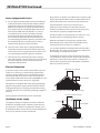
C. Using the angle bracket provided, fasten the bottom
front of the top unit to the main top of the bottom unit,
near the center, as shown.
Bottom of
Top Deck
Top of Bottom Deck
Angle Bracket
SIDE VIEW
D. Replace the combustion chamber on the top unit,
and fasten the two units together at the rear with the
mounting plates and screws provided.
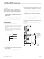
E. Install the two ue boxes and the ue riser to the rear of
the stack as shown.
F. Assemble the interconnecting gas piping as shown.
G. Start by threading the two tailpipes. Be sure to use a pipe
thread compound that is suitable for use on gas ttings.
H. Next install the 90° street elbow on the nipple of the top
unit, and then install the male part of the union on the
street elbow.
I. Install the 3/4” x 3/4” x 1” tee nipple of the bottom unit.
J. Install the 28-1/4” connection pipe to the second 3/4”
inlet on the tee, then install the male part of the union to
the other end of the connection pipe. Be sure to slide the
union’s hex-shaped fastening ring over the connecting
pipe before installing the male half.
K. Connect the top and bottom units’ piping with the union
as shown.
CAUTION: Disconnect both units from electrical supply
before servicing.
Flue Boxes
Flue
Riser
Mounting
Plates
3/4" 90 Deg
Street Elbow
3/4" Standard
Female Union
28 1/4"
Connecting Pipe
3/4" Close
Nipple
3/4" Close
Nipple
3/4" X 3/4" X 1"
Reducing Tee
1" NPT
Gas Inlet
REAR VIEW

Part # 1844082 (11/03/08)Page 8
OPERATION
Testing & Lighting
1. Turn on main gas valve. Remove the lower front cover
and open the control panel. Leak test all ttings and
connections upstream from the service valve. Use
approved gas leak detectors, soap solution or equivalent.
DO NOT USE A FLAME! Should any gas leaks be detected,
turn OFF main gas valve, correct the problem and retest.
2. Open shuto valve located below the control panel. Turn
the electrical supply on. Set the COOK/OFF/COOL switch
to the COOK position and adjust the thermostat knob to
the desired temperature. Electric spark will light the pilot
burner. Check all ttings again and correct any leaks and
recheck.
Replace all service panels and covers before operation.
NOTE: All electronic ignition systems are supplied with a
redundant gas valve. Therefore, the unit is not supplied with
an external pressure regulator.
NOTE: During installation there will be air in the gas line, this
air will have to bleed o before ignition can be established.
The electronic ignition system has a ninety second lock-out
as a safety device on all units. Therefore, several attempts
may be required before pilot ignition is established, wait ve
minutes after each attempt.
FOR YOUR SAFETY: KEEP YOUR APPLIANCE AREA FREE FROM
COMBUSTIBLES.
TO CONSERVE ENERGY Do not waste energy by leaving
controls at high temperature settings during idle periods.
Lower settings will keep oven warm and ready for next use
period. Reset controls as required for heavy load periods.
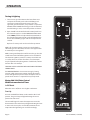
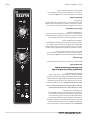
Master 200 Solid State Control
With Electromechanical Timer
In O Mode
When the oven is o, there are no lights or indicators.
Start Up
Press the Cook/O/Cool Down rocker switch to the “Cook”
position. The green lamp will light indicating the oven is
powered in cook mode.
The oven will begin to heat to the temperature set on the
thermostat dial. The amber lamp will light indicating the heat
is active. As the heat cycles on and o to maintain the set
temperature this light will go on and o accordingly.

Part # 1844082 (11/03/08) Page 9
The door must be closed for the oven to operate in cook
Mode. Opening the door will cause the heat to stop. The
motor and fan will shut o. This is a safety feature.
Fan Speed
The fan speed can be either high (1725RPM) or (1150 RPM).
The fan speed is controlled by the left rocker switch marked
high and low.
Cool Down
Pressing the Cook/O/Cool Down rocker switch to the Cool
Down position activates the fan and motor to cool the oven
cavity.
Optimal cool down will be achieved with the door open
slightly.
Pressing the button to the OFF position cancels the cool
down and turns the oven o.
Temperature
The temperature range is from 150°F to 500°F (66°C to 250°C)
is controlled by rotating the temperature dial and aligning
the indicator to the desired temperature.
Timer
The timer is set by rotating the dial clockwise aligning the
indicator to the desired time cycle. The timer will count down
from 2 minutes to 60 minutes. At the end of the timing cycle
the buzzer will sound. The buzzer is turned o by rotating the
dial counter-clockwise to the o position as shown on the
control panel.
NOTE: Timer does not control heat.
OPERATION Continued
PERFORMANCE RECOMMENDATIONS
Your GARLAND Convection Oven will give you the best
quality product and service if you familiarize yourself with
the following operation suggestions and information.
1. Preheat oven thoroughly (approximately. 20 minutes)
before use.
2. As a general rule, temperature should be reduced 25°
to 50° from that used in a standard/conventional oven.
Cooking time may also be shorter, so we suggest closely
checking the rst batch of each product prepared.
3. Use the chart of suggested times and temperatures as
a guide. These will vary depending upon such factors
as size of lead, temparature, and mixture of product
(particulary moisture) and density of product.
4. Keep a record of the times, temperature, and load sizes
you establish for various products. Once you have
determined these, they will be similar for succeeding
loads.
5. When practical, start cooking the lowest temperature
product rst and gradually work up to higher
temperatures.
6. If you nd that your previous temperature setting is more
that 10° higher than needed for succeeding loads, press
the COOL DOWN switch to reach the desired temperature
before setting a new cooking temperature.
7. When loading oven, work as quickly as possible to
prevent loss of heat.
8. Oven will continue to heat even though the timer goes
o. Product should be removed from the oven as soon as
possible to avoid over cooking.
9. Center pans on racks and load each shelf evenly to allow
for proper air circulation within the cavity.
10. When baking, weigh or measure the product in each pan
to assure even cooking.
11. When re-thermalizing frozen casseroles, preheat the oven
100° over the suggested temperature. Return to cooking
temperature when the oven is loaded. This will help
compensate for the introduction of a large frozen mass
into the cavity.
12. Never place anything directly on the bottom of the oven
cavity. This obstructs the airow and will cause uneven
results.
NOTE: Moisture will escape around the door when baking
products with heavy moisture content, such as chicken,
potatoes, and etc. This is normal.

Part # 1844082 (11/03/08)Page 10
COOKING GUIDE
The following suggested times and temperatures are provided as a starting guide. Elevation, atmospheric conditions, recipe,
cooking pans and oven loading may aect your actual results.
PRODUCT TEMPERATURE (ºF) TIME
Cakes
White Sheet Cakes – 5 lbs 300º 20 min
White Sheet Cakes – 6 lbs 300º 22 min
Yellow Sheet Cake – 21 oz 325º 15 min
Yellow Sheet Cake – 5 lbs 325º 22 min
Chocolate Layer Cake – 21 oz 300º 22 min
Angel Food Cake 375º 22 min
Brownies 350º 15 min
Breads
Soda Biscuits 400º 6 min
Yeast Rolls 325º 24 min
Sweet Bread 325º 24 min
Corn Bread 350º 22 min
Gingerbread 300º 24 min
Apple Turnovers 350º 25 min
Cream Pus 300º 25 min
Sugar Cookies 325º 12 min
Chocolate Chip cookies 375º 8 min
Apple Pie (Fresh) 375º 25 min
Blueberry Pie (Fresh) 350º 30 min
Blueberry Pie (Frozen) 300º 50 min
Pumpkin Pie (Frozen) 300º 50 min
Frozen Pizza 300º 6 min
Macaroni & Cheese 350º 15 min
Fish Sticks 350º 16 min
Stued Peppers 350º 45 min
Baked Potatoes 350º 60 min
Meats
Chicken Parts 350º 45 min
Hamburger Patties-10/lb Frozen 350º 8 min
Hamburger Patties - 10/lb Fresh 350º 5 min
Hamburger Patties - 4/lb Frozen 350º 12 min
Hamburger Patties – 4/lb Fresh 350º 8 min
Meatloaf – 4lb 325º 45 min
Bacon 350º 10 min
Roast Beef 20lb 325º 3 hr 15 min
Prime Rib 10lb 300º 1 hr 45 min
Stued Pork Chops 350º 45 min
Lamb Chops 375º 40 min
Boneless Veal Roast 300º 3 Hr

Part # 1844082 (11/03/08) Page 11
PROBLEMS/SOLUTIONS
Problem Solution
Cakes are dark on the sides and not done in the center Lower oven temperature
Cakes edges are too brown Reduce number of pans or lower oven temperature
Cakes have light outer color Raise temperature
Cake settles slightly in the center Bake longer or raise oven temperature slightly.
Do not open door too often or for long periods
Cake ripples Overloading pans or batter is too thin
Cakes are too coarse Lower oven Temperature
Pies have uneven color pans Reduce number of pies per rack
or eliminate use of bake pans
Cupcakes crack on top Lower oven temperature
Meats are browned and not done in center Lower temperature and roast longer.
Meats are well done and browned Reduce time. Limit amount of moisture
Meats develop hard crust Reduce temperature or place pan of water in oven.
Rolls have uneven color Reduce number or size of pans.
MAINTENANCE AND CLEANING
NOTE: Disconnect line cord from power supply before
cleaning or servicing.
Break-In Period
When oven is new, operate it for one hour at 375°F (191°C)
before you begin your normal cooking operation. After
cooling, wipe the interior, including the racks, with a clean
damp cloth.
Exterior Cleaning
Establish a regular schedule. Any spills should be wiped o
immediately.
1. The oven should always be allowed to cool suciently
before any cleaning is attempted.
2. Wipe exposed, cleanable surface when cool with a mild
detergent and hot water. Stubborn residue spots may be
removed with a lightweight non-metallic scouring pad.
Dry thoroughly with a clean cloth.
3. Stainless Steel surfaces can often be cleaned adequately
using a mild soap and warm water solution on a sponge
or soft cloth. Dry Thoroughly.
4. Stubborn stains may be removed by using a non-metallic
abrasive pad, rubbing in the direction of the metal’s grain.
If necessary, for particularly heavy deposits, you may mix
a thin paste of water and scouring powder, and apply
it with a sponge. Be careful to apply light pressure and
remember to rub only in the direction of the grain in the
metal.
5. The control panel surface is easily cleaned with hot water,
soap and a soft cloth. Do not use hard abrasives, solvent
type materials or metallic scouring pads since these will
scratch or cloud the surface.
6. Never spray the perforated areas or control panel with
steam or water, as this will allow moisture into the control
cavity, which could damage electrical components.

Part # 1844082 (11/03/08)Page 12
Interior Cleaning
Establish a regular cleaning schedule or wipe o on the same
day when spillovers occur.
1. Cool down oven.
2. Remove oven racks.
3. Lift rack guides on either side of oven o of holders. Racks
and guides may be run through dishwasher while oven
cavity is being cleaned.
4. Clean with soap and water using a non-metallic scouring
pad, if necessary. If dirt and grease have accumulated, a
mild ammonia solution or commercial oven cleaner such
as Easy-O or Dow may be used.
5. To reinstall, reverse procedure. Place the bottom of the
rack guide against the cavity wall. Keeping the top pulled
away from the wall lift up. Push the top of the guide
against the wall and push down locking it into place.
Fan Area Maintenance
If aluminum foil is routinely used to wrap food or cooking
vessels during oven operation, the following preventive
maintenance must be performed:
1. Turn power switch to “OFF” position
2. Remove oven racks and rack guides.
3. Remove air bae and clean any stains or deposits.
MAINTENANCE AND CLEANING Continued
4. Check blower wheel and air bae for particles of
aluminum foil or food deposits. Clean ns of blower
wheel. (Caution: edges of blower wheel ns may be
sharp).
5. Reinstall the air bae, rack guides and oven racks.
This simple practice, if performed on a regular basis will keep
your Garland oven operating at peak performance.
Motor Care
The motor on your convection oven is maintenance free
since it is constructed with self-lubricating sealed ball
bearings. It is designed to provide durable service when
treated with ordinary care. We have a few suggestions
to follow on the care of your motor. When the motor is
operating, it cools itself internally by air entering at the rear
of the motor case, provided proper clearance has been
allowed.
Since the blower wheel is in the oven cavity it is at the same
temperature as the oven. If the motor is stopped while the
oven is hot, the heat from the blower wheel is conducted
down the shaft and into the armature of the motor. This
action could shorten the life of the motor.
We recommend, at the end of the bake or roasting period,
when the oven will be idle for any period of time, or before
shutting down completely, that the door be left open
slightly. Set the COOK/OFF/COOL switch to COOL. Allow the
motor to run for approximately 30 minutes in Cool-Down.
Once cool, set the rocker switch to OFF.
NOTE: Optimal cool-down will be achieved with the door
open slightly.

Part # 1844082 (11/03/08) Page 13


Pièce nº 1844082 (11/03/08) Page 13
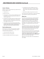
5. La surface du panneau de commande se nettoie
facilement avec de l’eau chaude, du savon et un chi on
doux. Ne pas utiliser de produits abrasifs durs, de solvants
ni de tampons à récurer métalliques qui peuvent ternir ou
rayer la surface.
6. Ne jamais asperger les parties perforées ou le panneau
de commande avec de la vapeur ou de l’eau, car cela fera
pénétrer de l’humidité dans la cavité des commandes et
pourrait endommager les composants électriques.
Nettoyage Intérieur
Établir un calendrier de nettoyage régulier ou essuyer le jour
même tout déversement.
1. Refroidir le four.
2. Retirer les grilles du four.
3. Soulever de leurs supports les guides de grilles d’un côté
du four, soulever la partie supérieure de la paroi du four,
passer les clips, pousser vers le bas et retirer. Les grilles et
les guides peuvent passer dans le lave-vaisselle pendant
le nettoyage de l’intérieur du four.
4. Nettoyer à l’eau et au savon doux en utilisant un
tampon à récurer non-métallique si nécessaire. En cas
d’accumulation de saleté et de graisse, on peut utiliser
une solution peu concentrée d’ammoniac ou un produit
de nettoyage pour fours du commerce comme Easy-O
ou Dow
5. Pour le remontage, inverser la procédure. Placer le bas du
guide de grille contre la paroi du four. En maintenant la
partie supérieure éloignée de la paroi, soulever. Pousser
le haut du guide contre la paroi et pousser vers le bas
pour le bloquer en place.
Maintenance De La Zone Du Ventilateur
Si on utilise habituellement du papier aluminium pour
envelopper les aliments ou les récipients de cuisson dans le
four, il est nécessaire d’e ectuer l’entretien préventif suivante
:
1 Mettre l’interrupteur d’alimentation en position « OFF ».
ENTRETIEN ET NETTOYAGE suite
2. Retirer les crémaillères et les guides des crémaillères du
four.
3. Retirer le dé ecteur d’air et nettoyer toutes les taches ou
dépôts.
4. Véri er la présence de particules d’aliments ou
d’aluminium sur le ventilateur et le dé ecteur. Nettoyer
les ailettes du ventilateur. (Attention : les bords des
ailettes peuvent être coupants).
5. Remettre en place le dé ecteur, les guides de crémaillère
et les crémaillères dans le four.
Cette pratique simple si elle est réalisée régulièrement,
maintiendra votre four Garland dans un état de
fonctionnement impeccable.
Entretien Du Moteur
Le moteur de ce four à convection est sans entretien étant
donné qu’il est fabriqué avec des roulements à billes
autolubri ants étanches. Il est conçu pour o rir un service
durable avec un entretien normal. Nous o rons ci-dessous
quelques suggestions à suivre en ce qui concerne le
moteur. Lors du fonctionnement du moteur, il se refroidit
automatiquement par l’air pénétrant dans la partie arrière de
son carter, à condition qu’un dégagement su sant existe à
l’arrière de l’appareil.
Étant donné que le ventilateur se trouve dans le four, il est
à la même température que celui-ci. Si le moteur est arrêté
pendant que le four est chaud, la chaleur du ventilateur
est transmise à l’arbre et à l’induit du moteur. Ceci peut
raccourcir la durée de vie du moteur.
Nous recommandons, à la n de chaque période de cuisson
ou de rôtissage ou avant l’arrêt complet, de laisser la porte
entrouverte. Placer le commutateur COOK/OFF/COOL en
position COOL. Laisser le moteur tourner pendant environ 30
minutes en refroidissement. Une fois le four refroidi, régler le
commutateur à bascule sur OFF.
NOTA : Le refroidissement optimal est obtenu avec la porte
du four entrouverte.

Pièce nº 1844082 (11/03/08)Page 12
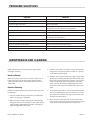
PROBLÈMES/SOLUTIONS
ENTRETIEN ET NETTOYAGE
REMARQUE: Débrancher le cordon électrique de la source
d’alimentation avant lenettoyage ou l’entretien.
Période De Rodage
Quand le four est neuf, le faire fonctionner pendant une
heure à 375°F (191°C) avant de commencer toute opération
normale de cuisson. Après refroidissement, essuyer
l’intérieur, y compris les grilles, avec un chi on propre et
humide.
Nettoyage Extérieur
Établir un calendrier de nettoyage régulier. Tout déversement
doit être essuyé immédiatement.
1. On devra toujours laisser le four refroidir su samment
avant de procéder au nettoyage.
2. Essuyer à froid les surfaces exposées et nettoyables avec
un chi on humecté d’une solution savonneuse non
abrasive et d’eau chaude. Les tâches rebelles peuvent être
retirées à l’aide d’un tampon à récurer non-métallique.
Bien essuyer avec un chi on propre.
3. Les surfaces en acier inoxydable peuvent être nettoyées
avec une solution d’eau tiède et de savon doux sur une
éponge ou un chi on doux. Sécher soigneusement.
4. Les taches rebelles peuvent être éliminées en utilisant
un tampon à récurer non métallique et en frottant
dans le sens du grain du métal. Si nécessaire, pour les
dépôts particulièrement importants, on peut utiliser une
pâte obtenue avec de l’eau et de la poudre à récurer et
l’appliquer avec une éponge. Faire attention à ne pas trop
appuyer et frotter uniquement dans le sens du grain du
métal.
Problèmes Solutions
Si le gâteau est doré sur les côtés
et n’est pas cuit au centre
Abaisser la température du four
Si les bords du gâteau sont brûlés Réduire le nombre de plats ou la température du four
Si la couleur du gâteau est pâle Augmenter la température
Si le gâteau s’a aisse légèrement au centre Prolonger le temps de cuisson ou augmenter légèrement la
température du four. Ne pas ouvrir la porte trop souvent ni
pendant de longues périodes de temps
Si le gâteau comporte des rides Surcharge des plats ou pâte trop ne
Si le gâteau est trop dur Abaisser la température du four
Si les tartes sont de couleur inégale Réduire le nombre de tartes par grille ou éliminer les moules
de cuisson
Si les petits gâteaux se fendent sur le dessus Abaisser la température du four
Si les viandes sont dorées mais pas cuites au centre Abaisser la température du four
et prolonger le temps de cuisson.
Si les viandes sont bien cuites et roussies Réduire le temps de cuisson.
Limiter la quantité d’humidité
Si les viandes ont une croûte dure Réduire la température ou placer un plat avec
de l’eau dans le four
Si les pains mollets sont de couleur inégale Réduire le nombre ou la taille des moules

Pièce nº 1844082 (11/03/08) Page 11
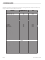
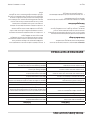
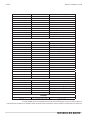
GUIDE DE CUISSON
Les temps et les températures suggérés suivants sont fournis comme guide de départ. L’altitude, les conditions atmosphériques,
la recette, les plats de cuisson et le chargement du four peuvent a ecter les résulats dé nitifs obtenus.
PRODUIT TEMPÉRATURE (ºF) TEMPS
Gâteaux
Gâteau Blancs Étagés – 5 lbs 300º 20 min
Gâteau Blancs Étagés – 6 lbs 300º
Gâteau Jaune Étagé – 21 oz 325º 15 min
Gâteau Jaune Étagé – 5 lbs 300º 22 min
Gâteau Étagé Au Chocolat – 21 oz 300º 22 min
Gâteau Des Anges 375º 22 min
Carrés Au Chocolat 350º 15 min
Pains
Biscuits À La Poudre Levante 400º 6 min
Petits Pains À la Levure 325º 24 min
Pain Viennois 325º 24 min
Pain De Maïs 350º 22 min
Pain D’épice 300º 24 min
Chaussons Aux Pommes 350º 25 min
Choux À La Crème 300º 25 min
Biscuits Aux Sucre 325º 12 min
Biscuits Aux Copeaux De Chocolat 375º 8 min
Tarte Aux Pommes (Fraîche) 375º 25 min
Tarte Aux Bleuets (Fraîche) 350º 30 min
Tarte Aux Bleuets (Congelée) 300º 50 min
Tarte À La Citrouille (Congelée) 300º 50 min
Congelée Pizza 300º 6 min
Macaronis Au Fromage 350º 15 min
Bâtonnets De Poisson 350º 16 min
Poivrons Farcis 350º 45 min
Pommes De Terre Au Four 350º 60 min
Viandes
Morceaux De Poulet 350º 45 min
Galettes De Bœuf -10/lb Congelée 350º 8 min
Galettes De Bœuf - 10/lb Fraîche 350º 5 min
Galettes De Bœuf - 4/lb Congelée 350º 12 min
Galettes De Bœuf – 4/lb Fraîche 350º 8 min
Pain De Viande – 4lb 325º 45 min
Bacon 350º 10 min
Rôti De Bœuf 20lb 325º 3 hr 15 min
Côte De Bœuf 10lb 300º 1 hr 45 min
Côtelettes De Porc Farcies 350º 45 min
Côtelettes D’agneau 375º 40 min
Rôti De Veau San Os 300º 3 Hr

Pièce nº 1844082 (11/03/08)Page 10
RECOMMANDATIONS D’UTILISATION
Ce four à convection GARLAND o rira à l’utilisateur les
meilleurs services et donnera les meilleurs résultats si
l’utilisateur se conforme aux suggestions et informations
d’utilisation suivantes.
1. Bien préchau er le four (environ 20 minutes) avant son
utilisation.
2. D’une façon générale, réduire la température de 25° à
50° par rapport à celle d’un four conventionnel/standard.
Le temps de cuisson peut également être plus court
et pour cette raison nous recommandons de surveiller
attentivement la première cuisson de chaque type de
produits.
3. Noter les temps de cuisson, les températures et les
quantités d’aliment pour les di érents produits. Une
fois ces renseignements notés, les autres opérations de
cuisson seront similaires.
4. Si possible, commencer par cuire les produits ayant
la température de cuisson la plus basse et passer
progressivement aux températures plus élevées
5. Si le réglage de température précédent est plus élevé
de 10° à la température nécessaire pour les charges
suivantes, utiliser le mode de refroidissement pour
atteindre la température souhaitée avant de régler à
nouveau le thermostat.
6. Pour charger le four, travailler aussi vite que possible pour
éviter les pertes de chaleur.
7. Le four continue à chau er même après l’arrêt de la
minuterie. Les aliments doivent être retirés du four aussi
vite que possible pour éviter de trop les faire cuire.
8. Centrer les plats dans le four et les répartir également sur
les grilles pour permettre une bonne circulation de l’air à
l’intérieur du fours.
9. Pour la pâtisserie, peser ou mesurer les produits dans
chaque moule pour assurer une cuisson régulière.
10. Pour le réchau age des plats en cocotte congelés,
préchau er le four à 100° de plus que la température
suggérée. Revenir ensuite à la température de cuisson
suggérée après le chargement du four. Cela permet de
compenser la chute de température provoquée par
l’introduction d’une grande quantité d’aliments froids
dans le four.
11. Ne jamais placer quoi que se soit directement sur le fond
du four. Cela empêche la circulation de l’air et cause une
cuisson inégale.
REMARQUE : Une certaine quantité d’humidité s’échappera
autour de la porte du four lors de la cuisson d’aliments à forte
teneur en humidité comme le poulet, les pommes de terre
etc. Cela est normal.
On obtient un refroidissement optimal avec la porte
légèrement ouverte.
Mettre le bouton en position « OFF » pour annuler le
refroidissement et éteindre le four.
Température
La plage de températures va de 150°F à 500°F (66°C à 250°C)
et est commandée en tournant le cadran de température et
en alignant l’indicateur sur la température souhaitée.
UTILISATION suite
Minuterie
La minuterie est réglée en tournant le bouton dans le
sens horaire pour aligner l’indicateur avec le cycle désiré
de minuterie. La minuterie décompte de 2 minutes à 60
minutes. À la n du cycle de minuterie, un signal sonore
retentit. On arrête le signal sonore en tournant le cadran
dans le sens inverse des aiguilles d’une montre en position «
O », comme indiqué sur le panneau de commande.
NOTA : La minuterie ne commande pas le chau age.

Pièce nº 1844082 (11/03/08) Page 9
REMARQUE :De l’air pénètrera dans la canalisation de gaz
pendant l’installation, et cet air doit être purgé avant de
procéder à l’allumage de l’appareil. Le système d’allumage
électronique est doté d’un verrouillage de 90 secondes
comme dispositif de sécurité sur tous les appareils. Par
conséquent, il peut être nécessaire de refaire plusieurs
tentatives avant l’allumage de la veilleuse. Attendre cinq
minutes après chaque tentative.
POUR LA SÉCURITÉ DE L’UTILISATEUR, ÉLOIGNER TOUTE
MATIÈRE COMBUSTIBLE DE LA ZONE ENTOURANTLE FOUR.
POUR ÉCONOMISER L’ÉNERGIE : Ne pas gaspiller l’énergie en
laissant les commandes sur les réglages forts pendant les
périodes d’inactivité. Des réglages plus bas maintiendront
le four chaud et prêt pour la période d’utilisation suivante.
Régler à nouveau les commandes si nécessaire pour les
périodes de forte utilisation.
Commande Transistorisée Master 200
Avec Minuterie Électromécanique
En mode d’arrêt
Quand le four est éteint, il n’y a aucun voyant ni indicateur.
Démarrage
Mettre le commutateur à bascule Cook/O /Cool Down en
position « Cook ». Le témoin vert s’allume, indiquant que le
four est sous tension et en mode de cuisson.
Le four commence à chau er pour atteindre la température
réglée sur le cadran du thermostat. Le témoin ambre s’allume
indiquant que le chau age est actif. Ce témoin s’allume et
s’éteint en même temps que le dispositif de chau age pour
maintenir la température réglée.
La porte doit être fermée pour que le four fonctionne en
mode de cuisson. L’ouverture de la porte arrête le dispositif
de chau age. Le moteur et le ventilateur s’arrêtent. Ceci est
une fonction de sécurité.
Vitesse du ventilateur
La vitesse du ventilateur peut être rapide (1 725 tr/min) ou
lente (1 150 tr/min). La vitesse du ventilateur est commandée
par l’interrupteur à bascule de gauche marqué High (rapide)
et Low (lent).
Refroidissement
Mettre le commutateur à bascule Cook/O /Cool Down
en position « Cool Down » pour activer le ventilateur et le
moteur a n de refroidir l’intérieur du four.
UTILISATION suite
La page est en cours de chargement...
La page est en cours de chargement...
La page est en cours de chargement...
La page est en cours de chargement...
La page est en cours de chargement...
La page est en cours de chargement...
La page est en cours de chargement...
La page est en cours de chargement...
-
 1
1
-
 2
2
-
 3
3
-
 4
4
-
 5
5
-
 6
6
-
 7
7
-
 8
8
-
 9
9
-
 10
10
-
 11
11
-
 12
12
-
 13
13
-
 14
14
-
 15
15
-
 16
16
-
 17
17
-
 18
18
-
 19
19
-
 20
20
-
 21
21
-
 22
22
-
 23
23
-
 24
24
-
 25
25
-
 26
26
-
 27
27
-
 28
28


Garland 36ER33-88 Mode d'emploi
- Catégorie
- Cuisinières
- Taper
- Mode d'emploi
dans d''autres langues
Documents connexes
-
Garland E20 Series Owner Instruction Manual
-
-
Garland Convection Microwave Oven Manuel utilisateur
-
Garland Master series Owner Instruction Manual
-
-
-
-
-
-
Garland MST44 Mode d'emploi