ACI Farfisa ZH1252W / ZH1252B Le manuel du propriétaire
- Taper
- Le manuel du propriétaire

- 1 -
Mi 2515-1
ITALIANOENGLISHFRANÇAISESPAÑOLPORTUGUÊSDEUTSCH
Mi 2515-1
ZH1252B
ZH1252W
4
1
"
"
16
8
/
/
13
1
123
29
6
"
8
/
5
168
Videocitofono vivavoce a
colori per sistema digitale DUO
Videocitofono a colori con schermo LCD
da 4,0" della serie DUO.
Per abilitare le funzioni videocitofoniche
sono disponibili 4 tasti; i tasti e
possono essere utilizzati anche per
effettuare le chiamate intercomunicanti.
Dati tecnici
Alimentazione: dalla linea
Assorbimento:
- a riposo: 6mA
- in funzionamento: 180mA
Schermo: 4" LCD
Temperatura funzionamento: 0° ÷ +40°C
Umidità massima: 90%RH
Hands Free Colour Video
Intercom for DUO digital system
Colour video intercom with 4.0" LCD
screen for DUO series.
To enable the video intercom functions,
4 keys are available on the front panel;
keys and can be used also to
make intercom calls.
Technical data
Power supply: directly from the line
Current:
- stand-by: 6 mA
- operating: 180 mA
Screen: 4" LCD
Operating temperature:0 °C to + 40 °C
Maximum humidity: 90% RH
Vidéophone mains libres
à couleurs pour système DUO
Vidéophone en couleurs avec écran LCD
de 4,0" de la série DUO.
4 touches servent pour les fonctions
du vidéophone; les touches et
peuvent être utilisées également pour
effectuer les appels inter-communicants.
Données techniques
Alimentation: directe de la ligne
Absorption:
- à repos: 6mA
- en fonctionnement: 180mA
Ecran: 4" LCD
Température de fonctionnement: 0°+40°C
Humidité maximum: 90%RH
Videoportero viva voz a
colores por sistema digital DÚO
Videoportero a colores con pantalla LCD
de 4,0" de la serie DUO.
Para habilitar las funciones del
videoportero están disponibles 4 teclas;
las teclas y pueden utilizarse
también para efectuar las llamadas de
intercomunicación.
Datos técnicos
Alimentación: de la línea
Absorbimiento:
- en reposo: 6 mA
- en funcionamiento: 180 mA
Pantalla: 4" LCD
Temp. de funcionamiento:0 °C to + 40 °C
Humedad máxima: 90% RH
Vídeo-porteiro viva voz a
cores para sistema digital DUO
Vídeo-porteiro da série DUO com
monitor LCD 4" a cores.
Existem 4 botões para activar as funções
de intercomunicação; os botões e
também podem ser utilizadas para
efectuar chamadas internas.
Dados técnicos
Alimentação: a partir da linha
Consumo:
- em estado de repouso: 6mA
- em funcionamento: 180mA
Monitor: 4" LCD
Temperatura funcionamento: 0° ÷ +40°C
Humidade máxima: 90%RH
Video-Gegensprechanlage
mit Farbbildschirm für das
digitale DUO-System
Video-Gegensprechanlage mit 4-Zoll-
LCD-Farbbildschirm, Baureihe DUO.
Für den Betrieb stehen 4 Tasten zur
Verfügung. Die Tasten und
steuern auch die Gesprächsverbindun-
gen.
Technische Daten
Stromversorgung: Leitung
Verbrauch:
- Ruhestellung: 6 mA
- in Betrieb: 180 mA
Bildschirm: LCD, 4"
Betriebstemperatur: 0° ÷ +40°C
Relative Luftfeuchtigkeit: 90%RH

- 2 -
Mi 2515-1
ITALIANOENGLISHFRANÇAISESPAÑOLPORTUGUÊS
DEUTSCH
AVVERTENZE DI SICUREZZA
Leggere attentamente le avvertenze
contenute nel presente manuale perché
forniscono importanti informazioni riguar-
danti la sicurezza di installazione, uso
e manutenzione. Conservarlo in modo
appropriato per future consultazioni.
Posizionare il videocitofono in ambiente
asciutto e lontano da fonti di calore o
apparecchiature che producono calore
e campi magnetici.
Per la pulizia del videocitofono non usare
acqua o solventi chimici, ma un panno
pulito.
Questo apparecchio deve essere de-
stinato solo all’uso per il quale è stato
concepito. Il costruttore non può essere
considerato responsabile per eventuali
danni derivati da usi impropri, erronei ed
irragionevoli.
Non lasciare alla portata dei bambini le
parti dell’imballaggio (sacchetti di plasti-
ca, polistirolo espanso, ecc.).
Non aprire l’apparecchio quando è acce-
so.
L’esecuzione dell’impianto deve essere
effettuato da personale specializzato ed
in conformità con le leggi vigenti.
In caso di guasto, funzionamento irrego-
lare o modica all’impianto avvalersi di
personale specializzato.
L’apparecchio è conforme alle direttive
CEE (marchio europeo CE).
SAFETY NOTICES
Read the instructions contained in this
manual carefully because they provide
important information about safe instal-
lation, use and maintenance. Keep this
manual appropriately for future refer-
ence.
Install your videointercom in a dry place
away from heat sources or devices that
produce heat and magnetic elds.
Do not clean the videointercom with
water or chemical solvents, use a dry
cloth for cleaning.
This device must be exclusively oper-
ated for its intended use. The manu-
facturer cannot be held responsible for
possible damage caused by improper,
erroneous and unreasonable use.
Keep packing parts away from children
(i.e. plastic bags, expanded polysty-
rene, etc.).
Do not open the device when it is on.
The installation must be made by spe-
cialized personnel in compliance with
the regulations in force.
Always refer to specialized personnel in
case of breakdown, irregular operation
or change in the installation.
The device complies with the EEC di-
rectives (CE European mark).
ADVERTENCIAS DE SEGURIDAD
Leer cuidadosamente las advertencias
contenidas en el presente manual porque
fornecen importantes informaciones con
respecto a la seguridad de instalación,
empleo y manutención. Conservarlo de
modo apropiado por futuras consultas.
Posicionar el videoportero en entornos
secos y lejos de fuentes de calor o
aparatos que producen calor y campos
magnéticos.
Por la limpieza del videoportero no usar
agua o solventes químicos sino un paño
limpio.
Este aparato tiene que sólo ser destinado
al empleo por el que ha sido concebido.
El constructor no puede ser considerado
responsable por eventuales daños deri-
vados por empleos impropios, erróneos
e irrazonables.
No dejar al alcance de los niños las par-
tes del embalaje, bolsitas de plástico,
poliestireno, etcétera.
No abrir el aparato cuando es encendido.
La ejecución de la instalación tiene que
ser efectuada de personal especializado
y en conformidad con las leyes vigentes.
En caso de avería, funcionamiento
irregular o modicación a la instalación
valerse de personal especializado.
El aparato está conforme a las directivas
CEE (marca europea CE).
AVISOS DE SEGURANÇA
Leia atentamente os avisos contidos
no presente manual porque trazem
importantes informações quanto à
segurança em termos de instalação,
utilização e manutenção. Guarde-o num
lugar seguro para eventuais consultas.
Posicione o vídeo porteiro num ambien-
te seco e longe de fontes de calor ou
de equipamentos que produzam calor
e campos magnéticos.
Para a limpeza do vídeo porteiro, não
use água nem solventes químicos, mas
somente um pano limpo.
Este aparelho é destinado somente
ao uso para o qual foi concebido.
O fabricante não se responsabiliza
por danos derivantes de utilizações
impróprias, erróneas ou irracionais.
Não deixe os elementos da embalagem
(sacos de plástico, polistirene expandido
etc.) ao alcance das crianças.
Não abra o aparelho quando ele estiver
ligado.
A instalação e o ensaio do equipamento
devem ser feitos por pessoal
especializado e em conformidade com
as leis vigentes.
Em caso de avaria, funcionamento
irregular ou alteração no equipamento,
recorra a pessoal especializado.
O aparelho é conforme as directivas
CEE (marca européia CE).
NOTICE DE SECURITÉ
Lire attentivement les instructions conte-
nues dans le présent manuel parce qu'ils
fournissent d'importants renseignements
concernant la sécurité d’installation,
d'usage et d'entretien. On recommande
le conserver de manière appropriée pour
consultations futures.
Positionner le moniteur en milieu sec et loin
de sources de chaleur ou d'appareillages
qui produisent chaleur ou champs magné-
tiques.
Pour la propreté du moniteur ne pas utiliser
de l'eau mais qu'un tissu propre.
Ce poste doit être destiné seulement
à l’usage pour lequel il a été conçu. Le
constructeur ne peut pas être considéré
comme responsable pour dommages
éventuels dérivés par l'utilisations impropres,
erronés et déraisonnables.
Ne pas laisser à la portée des enfants les
parties de l’emballage, sac en plastique,
polystyrène expansé, etc..
Ne pas ouvrir l’appareil quand il est en
marche.
L’exécution du montage et mise en œuvre
doivent être effectuées par personnel
spécialisé et en conformité avec les lois
en vigueur.
En cas de panne, fonctionnement irrégulier
ou modication à l’installation il faut se servir
de personnel spécialisé.
L’appareil est conforme à la directive CEE,
marque européenne CE.
SICHERHEITSHINWEISE
Hinweise im vorliegenden Handbuch
aufmerksam durchlesen, da sie wichtige
Informationen zur sicheren Installation,
Verwendung und Wartung enthalten.
Handbuch sorgfältig aufbewahren, um es
jederzeit wieder einsehen zu können.
Video-Gegensprechanlage in einem
trockenen Raum, fern von Wärmequellen
oder Geräten aufstellen, die Wärme oder
Magnetfelder erzeugen.
Video-Gegensprechanlage nicht mit
Wasser oder chemischen Lösungsmitteln,
sondern ausschließlich mit einem feuchten
Tuch reinigen.
Dieses Gerät darf nur für den vorgesehenen
Verwendungszweck benutzt werden.
Der Hersteller haftet nicht für Schäden,
die durch unsachgemäße oder falsche
Benutzung entstehen.
Verpackungsteile (Plastikbeutel, Styropor
usw.) dürfen nicht in Kinderhände gelangen.
Gerät im eingeschalteten Zustand nicht
öffnen.
Die Installation der Anlage darf nur vom
Fachmann entsprechend den geltenden
gesetzlichen Vorschriften vorgenommen
werden.
Bei Defekten, Betriebsstörungen oder
Änderungen an der Anlage ist ein Fachmann
hinzuzuziehen.
Gerät entspricht den EWG-Richtlinien
(europäisches CE-Kennzeichnung).

- 3 -
Mi 2515-1
ITALIANOENGLISHFRANÇAISESPAÑOLPORTUGUÊSDEUTSCH
LM
A1
LM
J1
2
1
3
4
J3
VOL
ON ON
A1
SW1
SW2
2
1
3
4 - Effettuare i collegamenti sulla morsettiera come
da schema da realizzare.
- Make the connections as required by the electric
diagram.
- Procéder aux branchements sur le bornier tel
que détaillé dans le schéma.
- Realizar las conexiones en la caja de bornes
como en el esquema de realización.
- Efectuar as ligações sobre a caixa de terminais
de acordo com o esquema a ser realizado.
-Klemmenbrett gemäß Schaltplan anschließen.
5 - Reinserire la morsettiera sul videocitofono.
- Plug-in back the terminal block on the videointercom.
- Réintroduire le bornier dans le vidéophone.
- Reintroducir la caja de bornes en el videoportero.
- Recolocar a caixa de terminais no vídeo-porteiro.
- Klemmenbrett wieder am Video-Gegensprechgerät anschließen.
LM
A1
LM
J1
2
1
3
4
J3
VOL
ON ON
A1
SW1
SW2
2
1
3
1 -Murare una scatola da incasso da 83mm o 60mm ad un'al-
tezza dalla pavimentazione di circa 1,5 m.
- Mount on the wall a built-in box of 83mm or 60mm at ap-
proximately 1.5 meters above the ground.
- Murer une boîte encastrable de 83 mm ou 60 mm à une
hauteur du sol d’environ 1,5 m.
- Acoplar a la pared una caja empotrada de 83mm o 60 mm
a una altura del suelo de aprox. 1,5 m.
- Edicar uma caixa de embutir de 83mm ou 60mm a uma
altura do piso de cerca 1,5 m.
- Eine Einbaudose (83 mm oder 60 mm) auf etwa 1,5 m Höhe
über dem Fußboden einbauen.
2 -Fissare la staffa alla scatola da incasso.
- Screw the bracket to the built-in box.
- Fixer le support à la boîte encastrable.
- Fijar el soporte a la caja empotrada.
- Fixar o suporte na caixa de embutir.
- Den Bügel an der Einbaudose xieren.
3 - Togliere la morsettiera dal videocitofono.
- Unplug the terminal block from the videointercom.
- Enlever le bornier du vidéophone.
- Extraer la caja de bornes del videoportero.
- Retirar a caixa de terminais do vídeo-porteiro.
- Klemmenbretter vom Video-Gegensprechgerät abtrennen.
1. INSTALLAZIONE - INSTALLATION - INSTALLATION
INSTALLACIÓN - INSTALLAÇÃO - EINBAU

- 4 -
Mi 2515-1
ITALIANOENGLISHFRANÇAISESPAÑOLPORTUGUÊS
DEUTSCH
7 - Smontaggio del videocitofono.
- Dismounting the video intercom.
- Démontage du vidéophone.
- Desmontaje del videoportero.
- Desmontagem do vídeo-porteiro.
- Video-Gegensprechgerät abbauen.
6 - Fissare il videocitofono alla staffa.
- Fix the video intercom to the wall bracket.
- Fixer le vidéophone sur le support de xation.
- Asegurar el videoportero al soporte de jación.
- Fixar o vídeo-porteiro ao suporte de xação.
- Video-Gegensprechgerät auf dem Halterungsbügel befestigen.
Morsetti
LM / LM Ingressi di linea
A1 / A1 Ingresso chiamata di piano
Terminal boards
LM / LM Line inputs
A1 / A1 Floor call input
Bornes
LM / LM Entrées de ligne
A1 / A1 Entrée appel d'étage
Terminales
LM / LM Entradas de línea
A1 / A1 Entrada llamada de piso
Terminais
LM / LM Entradas de linha
A1 / A1 Entrada chamada de patamar
Klemmen
LM / LM Leitungseingänge
A1 / A1 Eingang Klingelanschluss im Treppenhaus

- 5 -
Mi 2515-1
ITALIANOENGLISHFRANÇAISESPAÑOLPORTUGUÊSDEUTSCH
Regolazioni
Volume
In conversazione o durante la chiamata è
possibile cambiare il volume dell'audio e
della suoneria come indicato nel capitolo
3. Impostazioni. La regolazione VOL
VOL
posta sul retro del videocitofono non
è utilizzata.
Sensibilità microfono
Se durante la conversazione si ode un audio
intermittente o se durante una chiamata
l'altoparlante tende a distorcere, si consiglia
di ritoccare leggermente la sensibilità del
microfono agendo sul trimmer SENS
SENS
posto sul retro del videocitofono.
Colore e Luminosità.
Per regolare il colore e la luminosità
dell'immagine, girare con un piccolo gira-
vite i trimmer posti sul retro del di-
spositivo.
Adjustments
Volume
In conversation or during the call it is pos-
sible to change the volume of the audio and
of the ringtone as indicated in Chapter 3.
Settings. VOL adjustment
VOL
located
on the rear of the video-
intercom is not used.
Microphone sensitivity
If audio is excessively intermittent during
the conversation or the speaker tends to
distort it during the call, it is recommended
to slightly change the microphone sensitivity
using the SENS
SENS
trimmer on the back
of the videointercom.
Colour and Brightness
To adjust the colour and brightness
of the image, turn with a small screwdri-
ver, the trimmers located in the rear
of the device.
Réglages
Volume
En conversation ou pendant l’appel il est
possible de changer le volume de l’audio
et de la sonnerie comme indiqué dans le
chapitre 3. Congurations. Le réglage
VOL
VOL
placé sur l’arrière du vidéo-
phone n’est pas utilisé.
Sensibilité du microphone
Si pendant la conversation on entend un son
excessivement intermittent ou si pendant
un appel le haut-parleur tend à déformer,
on suggère de retoucher la sensibilité du
microphone légèrement en agissant sur le
trimmer SENS
SENS
mis sur le derrière du
moniteur.
Colore e Luminosità .
Pour régler la couleur et la luminosité
de l'image régler à l’aide d’un petit tour-
nevis les trimmers placés sur la
partie arrière du
dispositif.
Ajustes
Volumen
En conversación o durante la llamada es
posible cambiar el volumen del audio y del
timbre come se indica en el capítulo 3.
Planteamientos. El ajuste VOL
VOL
colocado detrás del videoportero no
se utiliza.
Calibrado de los niveles fónicos
Si durante la conversación se oye un audio
intermitente o si el altavoz tiende a torcer,
se aconseja retocar ligeramente la sen-
sibilidad del micrófono actuando sobre el
trimmer SENS
SENS
puesto en el reverso
del videoportero.
Color y Luminosidad
Para ajustar el color y la luminosidad
de la imagen ajuste con un pequeño
destornillador los trimmers colocados
detrás del dispositivo.
Regulações
Volume
O volume do som e da campainha pode
ser alterado durante a conversa ou a
chamada, tal como indicado no Capítulo
3. Congurações. O comando do VOL
VOL
situado na parte de trás do vídeo-
porteiro não é utilizado .
Calibragem dos níveis fónicos
Se, durante a conversação, ouvir um áudio
intermitente ou se, durante uma chamada,
o alto-falante tender a distorcer o som,
aconselha-se a retocar ligeiramente a
sensibilidade do microfone através do
compensador SENS
SENS
instalado na
parte traseira do vídeo porteiro.
Cor e Luminosidade.
Para ajustar a cor e a luminosidade
da imagem, utilize uma chave de fendas
pequena para ajustar o potenció-
metro situado na parte de trás do
aparelho.
Einstellungen
Lautstärke
Sie können die Lautstärke für Anrufe oder
Gespräche sowie das Läutwerk einstellen,
siehe Abschnitt 3. Einstellungen. Die Ein-
stellung VOL
VOL
auf der Geräterücksei-
te, ist nicht
genutzt.
Mikrofonempndlichkeit
Falls Sie bei Gesprächen Störgeräusche
hören oder der Lautsprecher verzerrt,
sollten Sie die Mikrofonempndlichkeit
regeln. Stellen Sie die Regelschraube
SENS
SENS
auf der Geräterückseite nach.
Farbe und Lichtstärke
Um Farbe und Lichtstärke zu regeln,
die Regelschrauben (Trimmer) auf
der Rückseite mit einem kleinen
Schraubendreher einstellen.
LM
A1
LM
J1
2
1
3
4
J3
SENS
VOL
Non utilizzato
Non utilisé
Not used
No utilizado
Nicht genutzt
Não utilizado
ON ON
A1
SW1
SW2
J4
2
1
3
Regolazione colore
Colour adjustment
Réglage couleur
Regulação cor
Ajuste color
Farbregelung
Regolazione luminosità
Brightness adjustment
Réglage luminosité
Regulação luminosidade
Ajuste luminisitad
Lichtstärke
Regolazione sensibilità del microfono
Adjusting microphone sensitivity
einstellen
Réglage sensibilité du microphone
Regulagem sensibilidade do microfone
Regulación sensibilidad del micrófono
Mikrofonempfindlichkeit

- 6 -
Mi 2515-1
ITALIANOENGLISHFRANÇAISESPAÑOLPORTUGUÊS
DEUTSCH
* Lettere di riferimento schematico (vedere lo schema a pagina 7).
** Distanza con il posto interno più lontano.
*** La lunghezza totale dei cavi dal derivatore ai posti interni non deve
superare i 300 metri (somma di tutte le tratte "E").
Tabella delle distanze massime garantite
Table of the maximum permitted distances
Tableau des distances maximales garanties
Tabla de las distancias máximas garantizadas
Tabela das distâncias máximas garantidas
Tabelle mit den gewährleisteten Höchstabständen
Tratta * Cavo Farsa 2302 Cavo telefonico Cavo CAT5
Section* Farsa 2302 cable Twisted cable CAT5 cable
Tronçon* Câble Farsa 2302 Câble torsadé Câble CAT5
Tramo* Cable Farsa 2302 Cable trenzado Cable CAT5
Trecho* Cabo Farsa 2302 Cabo trançado Cabo CAT5
Abschnitt* Kabel Farsa 2302 Telefonkabel Kabel CAT5
2x1mm² - AWG17 2x0,32mm² - AWG22 2x0,2mm² - AWG24
A 50 m - 164 ft 10 m - 33 ft 5 m - 17 ft
B 150 m - 328 ft 150 m - 328 ft 150 m - 328 ft
C ** 150 m - 328 ft 150 m - 328 ft 150 m - 328 ft
D 50 m - 164 ft 10 m - 33 ft 5 m - 17 ft
E *** 30 m - 164 ft 10 m - 33 ft 5 m - 17 ft
F ** 150 m - 328 ft 50 m - 164 ft 35 m - 115 ft
* Letters for reference on the diagrams (see page 7)
** Farthest internal station.
*** The total length of cables from line distributors to internal stations
should not exceed 300m (adding all the "E" sections).
* Lettres de référence schématique (voir à la page 7).
** Distance avec le poste interne plus éloigné.
*** La longueur totale des câbles du dérivateur aux postes internes ne
doit pas dépasser 300 mètres (somme de tous les tronçons “E”).
* Letras de referencia (véase la página 7).
** Distancia con el aparato interno más distante.
*** La longitud total de los cables del derivador a los aparatos inter-
nos no puede ser superior a los 300 metros (total de todos los
tramos “E”).
* Letras de referência esquemática (ver a página 7).
** Distância com o posto interno mais afastado.
*** O comprimento total dos cabos do derivador aos locais internos
não deve superar 300 metros (soma de todos os trechos “E”).
* Kennbuchstaben (siehe Seite 7).
** Abstand vom am weitesten entfernten Hausanschluss.
*** Kabellänge von der Abzweigung zu den Hausanschlüssen höch-
stens 300 m (Summe aller Abschnitte E).
Selezione impedenza di chiusura
Sul retro del videocitofono è posizionato
il ponticello J1 che permette di adattare il
segnale video proveniente dalla montante
e quindi migliorare la qualità dell'immagine
visualizzata.
Selección impedancia de cierre
Atrás del videoportero es posicionado el
puentecillo J1 que permite de adaptar la
señal video procedente del montante y por
lo tanto mejorar la calidad de la imagen
visualizada.
Selecting the closing impedance
The jumper J1 provided on the back of the
videointercom can be used to adjust the
video signal coming from the riser and thus
improve the quality of the image displayed.
Selecção da impedância
deencerramento
Na parte traseira do vídeo-porteiro está
posicionado o jumper J1, que permite a
adaptação do sinal de vídeo vindo da linha
vertical e, assim, melhorar a qualidade da
imagem visualizada.
Sélection impédance de ferme-
ture
Sur l’arrière du moniteur le petit pont J1 est
placé, il permet d’adapter le signal vidéo
provenant du montant et ainsi améliorer la
qualité de l'image afchée.
Verschlussimpedanz
Das durch die Steigleitung übertragene
Videosignal kann mit dem Jumper (Stecker)
J1 geregelt werden, um die Bildqualität zu
verbessern.
J1 Petit pont pour adapter l’impédance
du signal vidéo
J1 Impedanzregelung für das
Videosignal
J1 Ponticello per adattare l'impedenza
del segnale video
J1 Puentecillo para adaptar la impe-
dancia de la señal de video
J1 Jumper to adjust the impedance of
the video signal
J1 Jumper para adaptação da impe-
dância do sinal de vídeo
LM
A1
LM
J1
2
1
3
4
J3
VOL
ON ON
A1
SW1
SW2
2
1
3
J1
1
2
3
4
1-2
chiusura 100Ω (di fabbrica)
termination 100Ω (default)
fermeture 100Ω (d'usine)
cierre 100Ω (de fábrica)
fechar 100Ω (de fábrica)
Sperre 100Ω (ab Werk)
2-3
chiusura 15Ω
termination 15Ω
fermeture 15Ω
cierre 15Ω
fechar 15Ω
Sperre 15Ω
3-4
linea aperta
open line
ligne ouverte
línea abierta
linha aberta
offene Leitung

- 7 -
Mi 2515-1
ITALIANOENGLISHFRANÇAISESPAÑOLPORTUGUÊSDEUTSCH
DV2420
2221S
2221ML
230V
127V
0
D
J1
12345
J1
12345
LM
LM
LP
LP
PA
SE
2220
230V
127V
0
DV2421Q
DV2424Q
VD2120
LP
LP
LM
LM
LM
LM
LI LI
LO
LO
LO
LO
LI LI
LM
LM
A1
A1
LM
LM
A1
GN
FP
FP
A
B
E
E
C
TD2100..
CD213...
EC
EM
S1
S2
ZH1252
ZH1252
F
LO LO
LI LI
J1
12345
J1
12345
J1
12345
PRI
110V÷240VAC
VD2121CAG
AG21
LP
LP
PA
SE
LP
LP
PB
GN
S+
S-
VD2101AGL
AG21L
TD2000
J1
12345
DV2422A
L1
L1
L1
L1
LO
LO
LO
LO
LI LI
J1
12345
J1
12345
J1
12345
LI LI
L2
L2
L2
L2
IMPIANTO VIDEOCITOFONICO MULTIFAMILIARE
MULTI-FAMILY VIDEOINTERCOM SYSTEM
INSTALLATION VIDEOPHONIQUE A PLUSIEURS DIRECTIONS
SISTEMA DE VIDEOPORTERO MULTIFAMILIAR
INSTALAÇÃO DE VÍDEO-PORTEIRO MULTIFAMILIAR
MEHRFAMILIEN-VIDEO-GEGENSPRECHANLAGE
PA = Pulsante apriporta (opzionale)
Door release push-button (optional)
Bouton-poussoir ouvre porte (optionnel)
Pulsador abrepuerta (opcional)
Botão para abrir a porta (opcional)
Türöffner (bei Bedarf)
SE = Serratura elettrica (12Vca-1A max.)
Electric door lock (12VAC-1A max)
Gâche électrique (12Vca-1A max)
Cerradura eléctrica (12Vca-1A máx.)
Fechadura eléctrica (12Vca-1A max)
elektrisches Türschloss (12 V Ws - 1A max)
FP= Pulsante chiamata di piano (opzionale)
Floor call push-button (optional)
Bouton-poussoir de palier (optionnel)
Pulsador de piso (opcional)
Botão de patamar (opcional)
Klingelanschluss im Treppenhaus (bei Bedarf)

- 8 -
Mi 2515-1
ITALIANOENGLISHFRANÇAISESPAÑOLPORTUGUÊS
DEUTSCH
2. FUNZIONE DEI TASTI
I 4 tasti sul pannello frontale permettono di accedere alle funzioni ed alle regolazioni del dispositivo
e variano la loro funzione a seconda della modalità operativa del videocitofono. I tasti possono essere
utilizzati in due differenti modi:
1) pressione breve
2) pressione lunga (maggiore di 3 secondi).
Attenzione. Durante la pressione di un tasto, il tono di dissuasione o di occupato indica che la funzione non è disponibile
perché il servizio non è attivo o la linea videocitofonica è occupata da un altro utente.
Pressione lunga: > di 3 secondi
2.1 Funzione dei tasti a riposo
A riposo i tasti assumono le seguenti funzioni:
Tasto
Pressione breve
La funzione dipende dall'Indirizzo memorizzato
nel pulsante (per le programmazioni vedi paragrafo
4.1.2 Indirizzi associati al tasto), in dettaglio:
- indirizzo di un altro appartamento, si chiama
l'utente memorizzato;
- indirizzo di un'altra stanza dello stesso ap-
partamento, si chiama la stanza memorizzata;
- indirizzo di un attuatore, si attiva/disattiva
l'attuatore;
- indirizzi di posti esterni (max. 4), ad ogni
pressione si visualizzano, ciclicamente, le im-
magini dei relativi posti esterni.
Pressione lunga
Attiva/disattiva la funzione "silenzioso", esclu-
sione della suoneria e dei toni del dispositivo.
Quando la funzione "silenzioso" è attiva l'icona
lampeggia lentamente.
Pressione breve
Stesse funzioni del tasto , ad eccezione della
memorizzazione degli indirizzi dei posti esterni
che non è possibile.
Pressione lunga
Si accede al menù programmazione delle sonerie,
l'icona si accende ssa (vedi paragrafo 3.2
Sonerie).
Pressione breve
Aziona la serratura elettrica dell'ultimo posto
esterno che ha effettuato una chiamata.
Pressione lunga
Se programmato sul posto esterno, aziona l'at-
tuatore ausiliario dell'ultimo posto esterno che ha
effettuato una chiamata.
Pressione breve
Si collega con l'ultimo posto esterno che ha effet-
tuato una chiamata.
Pressione lunga
Come pressione breve.
>3 Sec

- 9 -
Mi 2515-1
ITALIANOENGLISHFRANÇAISESPAÑOLPORTUGUÊSDEUTSCH
3. IMPOSTAZIONI
I parametri che seguono possono essere modicati dall'utente
durante il normale uso del videocitofono.
3.1 Volume
L'utente può regolare il volume della conversazione
agendo sui tasti e ; è possibile regolare livelli
diversi per la conversazione con il posto esterno e per
quella intercomunicante; la regolazione avviene durante la
conversazione ed i livelli impostati, rimarranno validi anche
per le conversazioni successive.
2.2 Funzione dei tasti durante una conversazione
All'arrivo di una chiamata o durante una conversazione, i
tasti assumono le seguenti funzioni:
Tasto
Pressione breve
La funzione dipende dall'Indirizzo memorizzato
(per le programmazioni vedi paragrafo 4.1.2 In-
dirizzi associati al tasto), in dettaglio:
- indirizzo di un altro appartamento, nessuna
funzione;
- indirizzo di un'altra stanza dello stesso ap-
partamento, nessuna funzione;
- indirizzo di un attuatore, si attiva/disattiva
l'attuatore;
- indirizzi di posti esterni (max. 4), nessuna
funzione.
Pressione lunga
Attiva/disattiva la funzione "silenzioso" non si
sentiranno più la suoneria ed i toni del dispositivo.
Quando la funzione "silenzioso" è attiva l'icona
lampeggia lentamente.
Pressione breve
Stesse funzioni del tasto , ad eccezione della
memorizzazione degli indirizzi dei posti esterni
che sul tasto non è possibile.
Pressione lunga
Durante la conversazione permette di regolare il
volume audio, si accende l'icona e si hanno
circa 3 secondi di tempo per aumentare o
diminiure il volume dell'audio.
Pressione breve
Aziona la serratura elettrica dell'ultimo posto
esterno che ha effettuato una chiamata.
Pressione lunga
Se programmato sul posto esterno, aziona l'at-
tuatore ausiliario dell'ultimo posto esterno che ha
effettuato una chiamata.
Pressione breve
Attiva la conversazione audio con il posto esterno
o con l'apparecchio intercomunicante; se premuto
nuovamente, termina la conversazione in corso.
Pressione lunga
Se presente e programmata, commuta sulla te-
lecamera supplementare del posto esterno.
3.1.1 Livello audio con posto esterno
Durante una conversazione con il posto esterno premere
a lungo il tasto , si accende l'icona e si hanno circa
3 secondi di tempo per aumentare o diminuire
il volume dell'audio; il livello impostato sarà memorizzato
ed utilizzato anche per le future conversazioni con il posto
esterno.
3.1.2 Livello audio intercomunicante
Durante una conversazione intercomunicante premere a
lungo il tasto , si accende l'icona e si hanno circa
3 secondi di tempo per aumentare o diminuire il
volume dell'audio; il livello impostato sarà memorizzato ed
utilizzato anche per le future conversazioni intercomunicanti.
3.2 Sonerie
L'utente può modicare la melodia ed il numero degli squilli
per ciascuna tipologia di chiamata in arrivo; il volume è
invece lo stesso per tutte le chiamate.
Le tipologie di chiamata sono:
- da posto esterno
- da intercomunicante di palazzo
- da piano
- da intercomunicante di appartamento
3.2.1 Entrare in modalità programmazione soneria
Con il videocitofono a riposo, premere il tasto a lungo,
si entra in modalità programmazione soneria e si accende
l'icona ; se entro 10 secondi non verrà eseguita alcuna
operazione, il dispositivo esce automaticamente dalla
modalità di programmazione e si spegne l'icona .
3.2.2 Selezionare melodia
Le melodie disponibili sono:
- Din-don
- Classico
- Trillo alto
- Trillo basso
per selezionare la melodia premere più volte il tasto , le
melodie saranno selezionate in successione e riprodotte
dal dispositivo; dopo aver selezionato la melodia, passare
alla programmazione successiva.
3.2.3 Regolare il volume soneria
Con i tasti o si può abbassare o alzare il volume.
Attenzione: il volume della suoneria è unico per tutte
le tipologie di chiamata.
3.2.4 Impostare il numero di squilli
All'arrivo della chiamata ogni melodia può essere ripetuta
da 1 ad 8 volte (numero squilli), per cambiare il numero
di squilli premere più volte il tasto , ad ogni pressione si
incrementa di una unità il numero di squilli, un tono, ripetuto
n volte, indicherà quanti squilli sono stati selezionati.
3.2.5 Associare la suoneria al tipo di chiamata
Per terminare la programmazione è necessario attribuire la
soneria, precedentemente selezionata, al tipo di chiamata
che può essere:
- da posto esterno
- da intercomunicante di palazzo
- da piano
- da intercomunicante di appartamento

- 10 -
Mi 2515-1
ITALIANOENGLISHFRANÇAISESPAÑOLPORTUGUÊS
DEUTSCH
Per associare la soneria al tipo di chiamata, premere a
lungo il tasto:
per associarla alla chiamata da posto esterno
per associarla alla chiamata intercomunicante di
palazzo
per associarla alla chiamata da piano
per associarla alla chiamata intercomunicante di
appartamento
3.2.6 Uscire dalla modalità programmazione soneria
Aspettare circa 10 secondi senza premere alcun tasto,
il dispositivo esce automaticamente dalla modalità
programmazione e si spegne l'icona .
4. PROGRAMMAZIONI
Per poter funzionare correttamente, il videocitofono deve
essere programmato; se non sono richieste prestazioni
particolari l'unica programmazione necessaria è quella relativa
all'indirizzo utente, in questo caso passare direttamente al
paragrafo 4.2.1 Indirizzo utente e numero di stanza.
Attenzione: le programmazioni devono essere eseguite
da personale esperto (installatore), un'errata
programmazione può compromettere il corretto
funzionamento dell'intero impianto videocitofonico.
4.1 Programmazioni di sistema
Le programmazioni che possono essere effettuate sono:
- indirizzi associati al tasto
- Indirizzo associato al tasto
- indirizzo rilancio chiamata da piano
- indirizzi secondari del videocitofono
Per le programmazioni seguire le modalità descritte nei
paragra successivi.
4.1.1 Entrare in programmazione di sistema
Per accedere alle programmazioni di sistema è necessario
spostare il ponticello J4 dalla posizione 2-3 alla posizione
1-2, si accende l'icona .
4.1.2 Indirizzi associati al tasto
Al tasto possono essere associati 1 indirizzo di
appartamento e di stanza, per le chiamate intercomunicanti
o 1 indirizzo attuatore oppure no a 4 indirizzi di posti
esterni per poterli controllare in sequenza.
- Programmazione Indirizzo Intercomunicante di
Palazzo:
con i microinterruttori SW1 impostare l'indirizzo di
appartamento desiderato e con i microinterruttori SW2
impostare il numero di stanza 0 (vedi tabella a pagina
39); premere a lungo il tasto no a che un tono non
confermerà l'avvenuta memorizzazione.
- Programmazione Indirizzo Intercomunicante di
Appartamento:
con i microinterruttori SW1 impostare l'indirizzo del proprio
appartamento e con i microinterruttori SW2 impostare il
numero di stanza, da 0 a 3 (vedi tabella a pagina 39);
premere a lungo il tasto no a che un tono non
confermerà l'avvenuta memorizzazione.
- Programmazione Indirizzo Attuatore:
con i microinterruttori SW1 impostare l'indirizzo
dell'attuatore che si intende comandare (da 211 a 230)
e con i microinterruttori SW2 impostare il numero di
stanza 0 (vedi tabella a pagina 39); premere a lungo il
tasto no a che un tono non confermerà l'avvenuta
memorizzazione.
- Programmazione Indirizzi Posti Esterni:
nel tasto è possibile programmare no a 4 indirizzi di
posti esterni con i quali ci si collegherà in sequenza ad ogni
pressione del tasto. Con i microinterruttori SW1 impostare
l'indirizzo del primo posto esterno, ed impostare 0 sui
microinterruttori SW2, (vedi tabella a pagina 39); premere
a lungo il tasto no a che un tono non confermerà
l'avvenuta memorizzazione del primo indirizzo. Se si
intende programmare un secondo indirizzo è necessario
impostare i microinterruttori SW1 con l'indirizzo del
secondo posto esterno, lasciando a 0 i microinterruttori
SW2 (vedi tabella a pagina 39) e premere a lungo il tasto
no a che due toni non confermeranno l'avvenuta
memorizzazione del secondo indirizzo. Procedere in
maniera analoga per la programmazione del terzo e quarto
indirizzo del posto esterno, l'avvenuta programmazione
è confermata rispettivamente da tre o quattro toni.
Per cambiare gli indirizzi memorizzati è necessario uscire
dalla programmazione, attendere 3 secondi e rientrare in
programmazione; impostare con SW1 il nuovo indirizzo,
lasciando SW2 a 0 e premere a lungo il tasto no a
che un tono non confermerà l'avvenuta memorizzazione
del nuovo primo indirizzo; procedere in modo analogo per
cambiare l'eventuale secondo, terzo e quarto indirizzo. Per
cancellare gli indirizzi memorizzati è necessario impostare
il codice 255 su SW1 e 0 su SW2 (vedi tabella a pagina
39) e premere a lungo il tasto no a che un tono non
confermerà l'avvenuta cancellazione del primo indirizzo;
procedere in modo analogo per cancellare l'eventuale
secondo, terzo e quarto indirizzo memorizzato.
4.1.3 Indirizzi associati al tasto
Al tasto possono essere associati 1 indirizzo di
appartamento e di stanza per chiamate intercomunicanti
o 1 indirizzo attuatore.
- Programmazione Indirizzo Intercomunicante di
Palazzo:
con i microinterruttori SW1 impostare l'indirizzo di
appartamento desiderato e con i microinterruttori SW2
impostare il numero di stanza 0 (vedi tabella a pagina
39); premere a lungo il tasto no a che un tono non
confermerà l'avvenuta memorizzazione.
- Programmazione Indirizzo Intercomunicante di
Appartamento:
con i microinterruttori SW1 impostare l'indirizzo del
proprio appartamento e con i microinterruttori SW2
impostare il numero di stanza, da 0 a 3 (vedi tabella a
pagina 39); premere a lungo il tasto no a che un
tono non confermerà l'avvenuta memorizzazione.
- Programmazione Indirizzo Attuatore:
con i microinterruttori SW1 impostare l'indirizzo
dell'attuatore che si intende comandare (da 211 a 230)
e con i microinterruttori SW2 impostare il numero di
stanza 0 (vedi tabella a pagina 39); premere a lungo il
tasto no a che un tono non confermerà l'avvenuta
memorizzazione.

- 11 -
Mi 2515-1
ITALIANOENGLISHFRANÇAISESPAÑOLPORTUGUÊSDEUTSCH
Per cambiare l'indirizzo memorizzato è necessario
impostare con SW1 ed SW2 i nuovi codici e premere
a lungo il tasto no a che un tono non confermerà
l'avvenuta memorizzazione, invece per cancellare l'indirizzo
memorizzato è necessario impostare il codice 255 su SW1
e 0 su SW2 (vedi tabella a pagina 39) e premere a lungo
il tasto no a che un tono non confermerà l'avvenuta
cancellazione.
4.1.4 Indirizzo rilancio chiamata da piano
All'arrivo di una chiamata da piano squilla solo il monitor
a cui è collegato il pulsante di chiamata, se si intende
rilanciare la chiamata anche su tutti gli altri monitor presenti
nell'appartamento o in un altro appartamento, occorre:
- con i microinterruttori SW1 impostare l'indirizzo del
videocitofono principale dell'appartamento a cui si intende
rilanciare la chiamata e con i microinterruttori SW2
impostare il numero di stanza 0 (vedi tabella a pagina
39); premere a lungo il tasto no a che un tono non
confermerà l'avvenuta memorizzazione.
Attenzione: il rilancio di chiamata farà squillare tutti
i videocitofoni (sia principali che secondari) presenti
nell'appartamento a cui è stata rilanciata la chiamata
da piano.
Per cambiare l'indirizzo memorizzato è necessario
impostare con SW1 ed SW2 i nuovi codici e premere a
lungo il tasto no a che un tono non confermerà l'avvenuta
memorizzazione; per cancellare l'indirizzo memorizzato è
necessario impostare il codice 255 su SW1 e 0 su SW2
(vedi tabella a pagina 39) e premere a lungo il tasto no
a che un tono non confermerà l'avvenuta cancellazione.
4.1.5 Indirizzi aggiuntivi
Un videocitofono può essere abilitato a ricevere anche
le chiamate indirizzate ad altri utenti (max 4), per la
programmazione dei relativi indirizzi occorre:
- con i microinterruttori SW1 impostare l'indirizzo del
primo utente per il quale si vuole rispondere e con i
microinterruttori SW2 il relativo numero di stanza (vedi
tabella a pagina 39); premere a lungo il tasto no a che
un tono non confermerà l'avvenuta memorizzazione del
primo indirizzo. Se si intende programmare altri indirizzi
aggiuntivi è necessario impostare i microinterruttori SW1
con l'indirizzo del secondo utente per il quale si vuole
rispondere e i microinterruttori SW2 con il relativo numero
di stanza (vedi tabella a pagina 39); premere a lungo il
tasto no a che due toni non confermeranno l'avvenuta
memorizzazione del secondo indirizzo. Procedere in
maniera analoga per la programmazione dell'indirizzo del
terzo e quarto utente per i quali si desidera rispondere,
l'avvenuta programmazione è confermata rispettivamente
da tre o quattro toni.
Per cambiare gli indirizzi memorizzati è necessario uscire
dalla programmazione, attendere 3 secondi e rientrare
in programmazione; impostare con SW1 ed SW2 i nuovi
codici e premere a lungo il tasto no a che un tono
non confermerà l'avvenuta memorizzazione del nuovo
primo indirizzo aggiuntivo; procedere in modo analogo per
cambiare l'eventuale secondo, terzo e quarto indirizzo. Per
cancellare gli indirizzi memorizzati è necessario impostare
il codice 255 su SW1 e 0 su SW2 (vedi tabella a pagina
39) e premere a lungo il tasto no a che un tono non
confermerà l'avvenuta cancellazione del primo indirizzo;
procedere in modo analogo per cancellare l'eventuale
secondo, terzo e quarto indirizzo memorizzato.
4.1.6 Uscire dalla programmazione di sistema
Per uscire dalla programmazione riportare il ponticello J4
dalla posizione 1-2 alla posizione 3-4, si spegnerà l'icona
.
4.1.7 Ripristino programmazioni di fabbrica
Per ripristinare le programmazioni di fabbrica occorre:
- entrare in modalità programmazione (vedi paragrafo
4.1.1);
- premere in sequenza i tasti → → → ;
- per 1 sec. si accende l'icona e si spegne l'icona
le impostazioni del dispositivo e le programmazioni di
sistema sono ritornate ai valori di fabbrica;
- uscire dalla modalità programmazione (vedi paragrafo
4.1.6).

- 12 -
Mi 2515-1
ITALIANOENGLISHFRANÇAISESPAÑOLPORTUGUÊS
DEUTSCH
4.2 Programmazioni videocitofono
Per la programmazione del dispositivo è necessario impostare
i codici che identicano il videocitofono rispettivamente
all'interno dell'impianto (indirizzo utente da 001 a 200) ed
all'interno dell'appartamento (numero di stanza da 0 a 3).
Per l'indirizzo utente tenere presente che:
- non deve essere lo stesso numero di un altro
appartamento; se più posti interni in parallelo sono
presenti nell'appartamento, devono avere lo stesso
indirizzo utente ma diverso numero di stanza (vedi
paragrafo successivo);
- deve coincidere con il numero memorizzato nella pulsantiera
esterna e nell'eventuale centralino di portineria;
- deve essere memorizzato nel tasto di chiamata o nei
contatti dell'apparecchio di un altro utente se occorre
intercomunicare tra i due appartamenti.
Per il numero di stanza tenere presente che:
- Il numero di stanza stabilisce anche una gerarchia negli
apparati interni in quanto l’apparecchio che avrà il
numero di stanza 0 (zero) sarà denito principale, gli
altri saranno tutti secondari.
- Il differente numero di stanza consente di effettuare e ricevere
selettivamente le chiamate tra apparecchi all’interno dello
stesso appartamento; le chiamate da esterno o da altro
appartamento faranno squillare tutti i dispositivi, il primo
che risponderà attiverà la conversazione e spegnerà le
sonerie degli altri.
- all’arrivo di una chiamata da posto esterno videocitofonico
tutti gli apparecchi squillano, ma solo il principale (numero di
stanza 0 "zero") mostra l’immagine della telecamera. Dagli
altri videocitofoni dello stesso appartamento, è possibile
visionare l'ingresso premendo il tasto , tale operazione
disattiva tutte le sonerie, accende il videocitofono e
contemporaneamente spegne il videocitofono principale.
4.2.1 Indirizzo utente e numero di stanza.
Per programmare l'indirizzo utente ed il numero di stanza del
videocitofono non occorre alcuna procedura, è sufciente
posizionare i microinterruttori SW1 ed SW2 in accordo con
la tabella riportata a pagina 39; (di fabbrica il videocitofono
è programmato con indirizzo utente 100 e numero di
stanza 0).
Attenzione: poiché i microinterruttori SW1 ed SW2
sono utilizzati anche per eseguire altre programmazioni
(vedi paragrafo 4.1 Programmazioni di sistema), la
loro posizione potrebbe essere stata modicata.
Prima di utilizzare il dispositivo ricordarsi di
posizionare i microinterruttori SW1 ed SW2 in
accordo con l'indirizzo utente ed il numero di stanza
che si intende attribuire al videocitofono.
5. FUNZIONAMENTO
5.1 Videocitofonia
A seguito di una chiamata dal posto esterno il videocitofono
squilla e sullo schermo appare l'immagine per circa 30
secondi. Premendo il tasto si può conversare con l'esterno
per un tempo di circa 90 secondi, durante la conversazione
per spegnere anticipatamente il videocitofono, premere il
tasto .
La serratura elettrica si aziona premendo il tasto ; il
comando funziona anche senza ricevere alcuna chiamata,
in questo caso si aziona la serratura elettrica dell'ultimo
ingresso che ha chiamato o è stato attivato.
Durante una conversazione videocitofonica, premendo
a lungo il tasto , si ha la possibilità di effettuare la
regolazione del volume audio (vedi paragrafo 3.1 Volume).
La suoneria può essere disattivata premendo a lungo il
tasto ; il simbolo lampeggia per indicare l'avvenuta
disattivazione e continuerà a lampeggiare no a quando
la suoneria non sarà riattivata con modalità analoga alla
disattivazione.
Con il monitor a riposo, premendo il tasto , si visualizza
l'immagine proveniente dall'ultimo posto esterno che
ha effettuato una chiamata. Premendo il tasto , se
opportunamente programmato, si possono visualizzare
le immagini provenienti da altri posti esterni, se presenti
nell'impianto (max 4). Per le programmazioni dei tasti vedi
paragrafo 4.1 Programmazioni di sistema.
5.2 Intercomunicante
Con i tasti e , se opportunamente programmati,
si possono chiamare altri apparecchi presenti nello stesso
appartamento o nello stesso palazzo. Per le programmazioni
dei tasti vedi paragrafo 4.1 Programmazioni di sistema.

- 13 -
Mi 2515-1
ITALIANOENGLISHFRANÇAISESPAÑOLPORTUGUÊSDEUTSCH
2. FUNCTION OF THE KEYS
The 4 frontal keys allow accessing the functions and the settings of the device and vary their function
depending on the operating mode of the video intercom. The keys can be used in two different ways:
1) short pressure
2) long pressure (over 3 seconds).
Attention. During the pressure of a key, the dissuasion or busy tone indicates that the function is not available because
the service is not active or the video intercom line is busy by another user.
Long pressure: > 3 Seconds
2.1 Function of the keys in stand-by
In stand-by, the keys have the following functions:
Keys
Short pressure
The function depends on the Address stored in
the pushbutton (for programming see paragraph
4.1.2 Addresses associated to the key), in detail:
- address of another apartment, the stored
user is called;
- address of another room of the same apart-
ment, the stored room is called;
- address of an actuator, the actuator is acti-
vated/deactivated;
- addresses of external stations (max. 4), at
each pressure are displayed, cyclically, the
images of the related external stations.
Long pressure
It activates/deactivates the “silent” function, exclu-
sion of the ringtone and the tones of the device.
When the “silent” function is active, icon blinks
slowly.
Short pressure
Same functions of key , except for the storing
of the addresses of the external stations, which
is not possible.
Long pressure
It is accessed to the programming menu of the
ringtones; icon lights up (see paragraph 3.2
Ringtones).
Short pressure
It activates the electrical lock of the last external
station that has made a call.
Long pressure
If programmed on the external station, it activates
the auxiliary actuator of the last external station
that has made a call.
Short pressure
It connects with the last external station that has
made a call.
Long pressure
As short pressure.
>3 Sec

- 14 -
Mi 2515-1
ITALIANOENGLISHFRANÇAISESPAÑOLPORTUGUÊS
DEUTSCH
3. SETTINGS
The parameters that follow can be modied by the user during
normal use of the video intercom.
3.1 Volume
The user can adjust the volume of the conversation by
acting on keys and ; it is possible to adjust different
levels for conversation with the external station and for the
intercommunication; the adjustment takes place during the
conversation and the set levels will remain valid also for le
next conversations.
3.1.1 Audio level with external door station
During a conversation with the external station press for a
long time key ; icon lights up and there are about
3 seconds to increase or decrease , the audio
volume; the set level will be stored and used also for future
conversations with the external station.
3.1.2 Intercommunicating audio level
During an intercommunicating conversation press for a
long time key ; icon lights up and there are about
3 seconds to increase or decrease , the audio
volume; the set level will be stored and used also for future
intercommunicating conversations.
3.2 Ringtones
The user can modify the melody and the number of rings
for each type of call in arrival; instead, the volume is the
same for all calls.
The types of calls are:
- from external station
-fromintercommunicatingblockofats
-fromoor
- from intercommunicating apartment
3.2.1 Entering in the ringtone programming mode
With the video intercom in stand-by, press key for a long
time, the ringtone programming mode is entered and icon
lights up; if within 10 seconds no operation will occur,
the device exits automatically from the programming mode
and icon turns off.
3.2.2 Select melody
The available melodies are:
- Din-don
- Classic
- High trill
- Low trill
To select the melody press repeatedly key ; the melodies
will be selected in sequence and reproduced by the
device; after having selected the melody, pass to the next
programming.
3.2.3 Adjust the ringtone volume
With keys or the volume can be lowered or raised.
Attention: the volume of the ringtone is the same for
all types of calls.
3.2.4 Settting the number of rings
Upon arrival of the call each melody can be repeated from
1 to 8 times (number of rings); to change the number of
rings press repeatedly key ; at each pressure the number
of rings increases by one unit; a tonality, repeated n times,
will indicate the number of rings that have been selected.
3.2.5 To associate the ringtone to the type of call
To end programming, it is necessary to attribute the
previously selected ringtone to the type of call that can be:
- from external station
-fromintercommunicatingblockofats
-fromoor
- from intercommunicating apartment
2.2 Function of the keys during a conversation
Upon arrival of a call or during a conversation, the keys have
the following functions:
Keys
Short pressure
The function depends on the Address stored in
the pushbutton (for programming see paragraph
4.1.2 Addresses associated to the key), in detail:
- address of another apartment, no function;
- address of another room of the same apart-
ment, no function;
- address of an actuator, the actuator is acti-
vated/deactivated;
- addresses of external stations (max. 4), no
function.
Long pressure
It activates/deactivates the “silent” function, exclu-
sion of the ringtone and the tones of the device.
When the “silent” function is active, icon blinks
slowly.
Short pressure
Same functions of key , except for the storing
of the addresses of the external stations which on
key is not possible.
Long pressure
During the conversation it allows adjusting the au-
dio volume; icon lights up and there are about
3 seconds to increase or decrease the
audio volume.
Short pressure
It activates the electrical lock of the external sta-
tion that has made a call.
Long pressure
If programmed on the external station, it activates
the auxiliary actuator of the external station that
has made a call.
Short pressure
It activates the audio conversation with the call-
ing door station or intercommunicating device; if
pressed once again, it terminates the conversation
in progress.
Long pressure
If it is present and programmed, it switches over
on the additional camera of the door station.

- 15 -
Mi 2515-1
ITALIANOENGLISHFRANÇAISESPAÑOLPORTUGUÊSDEUTSCH
To associate the ringtone to the type of call, press for a
long time key:
to associate it to the call from external station
to associate it to the call from intercommunicating
block of ats
to associate it to the call from oor
to associate it to the call from intercommunicating
apartment
3.2.6 Exit from the ringtone programming mode
Wait about 10 seconds without pressing any key; the device
exits automatically from the programming mode and icon
turns off.
4. PROGRAMMING
To function properly, the video intercom must be programmed;
if no special performance are required the only needed
programming is that related to the user address, in this case
pass directly to paragraph 4.2.1 User Address and number
of room.
Attention: the programming must be performed by expert
(installer), incorrect programming can prevent proper
operation of the entire video intercom system.
4.1 System programming
The programming that can be performed are:
- addresses associated to the key
- address associated to the key
-callre-launchaddressfromoor
- secondary addresses of the video intercom
For programming, follow the methods described in the
following paragraphs.
4.1.1 Entering into the system programming
For accessing to the system programming jumper J4 must
be moved from position 2-3 to position 1-2; icon lights up.
4.1.2 Addresses associated to key
To key can be associated 1 address of apartment and
of room for intercommunicating calls, or 1 actuator address
or up to 4 addresses of external stations to be able to control
them in sequence.
- Programming Building Intercommunicating Address:
with microswitches SW1 set the address of the desired
apartment and with microswitches SW2 set the room
number 0 (see table on page 39); press for a long time
key until a tone will conrm the occurred storing.
- Programming Apartment Intercommunicating Address:
with microswitches SW1 set the address of your apartment
and with microswitches SW2 set room number, from 0 to
3 (see table page 39; press for a long time key until
a tone will conrm the occurred storing.
- Programming Actuator Address:
with microswitches SW1 set the actuator address which is
intended to control (from 211 to 230) and with microswitches
SW2 set the room number 0 (see table on page 39);
press for a long time key until a tone will conrm the
occurred storing.
- Programming External Station Addresses:
in the key , it is possible to programme up to 4 addresses
of external stations with which it will be connected in
sequence at each pressure of the key. With micro-switches
SW1 set the address of the rst external station, and set 0
on microswitches SW2, (see table on page 39); press for
a long time key until a tone will conrm the occurred
storing of the rst address. If it is intended to programme
a second address, it is necessary to set microchips SW1
with the address of the second external station leaving at
0 microswitches SW2 (see table on page 39) and press
for a long time key until two tones will conrm the
occurred storing of the second address. Proceed in a
similar manner to the programming of the third and fourth
external station address, the occurred programming is
conrmed respectively by three or four tones.
To change the stored addresses, it is necessary to exit
from the programming, wait 3 seconds and re-enter in
programming; with SW1 set the new address, leaving
SW2 at 0 and press for a long time key until a tone
will conrm the occurred storing of the new rst address;
proceed in a similar manner to change the eventual second,
third and fourth address. To delete the stored addresses, it
is necessary to set code 255 on SW1 and 0 on SW2 (see
table on page 39) and press for a long time key until
a tone will conrm the occurred cancellation of the rst
address; proceed in a similar way to cancel any second,
third and fourth stored address.
4.1.3 Addresses associated to key
To key can be associated 1 address of apartment and
of room for intercommunicating calls, or 1 actuator address.
- Programming Building Intercommunicating Address:
with microswitches SW1 set the address of the desired
apartment and with microswitches SW2 set the room
number 0 (see table on page 39); press for a long time
key until a tone will conrm the occurred storing.
- Programming Apartment Intercommunicating Address:
with microswitches SW1 set the address of your apartment
and with microswitches SW2 set room number, from 0 to
3 (see table page 39); press for a long time key until
a tone will conrm the occurred storing.
- Programming Actuator Address:
with microswitches SW1 set the actuator address that it is
intended to control (from 211 to 230) and with microswitches
SW2 set the room number 0 (see table on page 39);
press for a long time key until a tone will conrm the
occurred storing.
To change the stored address, it is necessary to set with
SW1 and SW2 the new codes and press for a long time key
until a tone will conrm the occurred storing; instead
to delete the stored address, it is necessary to set code
255 on SW1 and 0 on SW2 (see table on page 39) and
press for a long time key until a tone will conrm the
occurred cancellation.
4.1.4 Forwardingaoorcall
Upon arrival of a call from a oor, only the monitor to which
the call pushbutton is connected rings. If it is intended to
relaunch the call also on all the other monitors present in
the apartment or in another apartment, it is necessary to
proceed as follows:
- with microswitches SW1 set the address of the main
video intercom of the apartment to which it is intended to

- 16 -
Mi 2515-1
ITALIANOENGLISHFRANÇAISESPAÑOLPORTUGUÊS
DEUTSCH
forward the oor call and with microswitches SW2 set the
room number 0 (see table on page 39); press for a long
time key until a tone will conrm the occurred storing.
Attention: when forwarding a oor call, all video
intercoms (both main and secondary) present in the
apartment to which the oor call was forwarded will
ring.
To change the stored address, it is necessary to set with
SW1 and SW2 the new codes and press for a long time key
until a tone will conrm the occurred storing; instead, to
delete the stored address, it is necessary to set code 255
on SW1 and 0 on SW2 (see table on page 39) and press
for a long time key until a tone will conrm the occurred
cancellation.
4.1.5 Additional Addresses
A video intercom can be enabled to receive also the calls
addressed to other users (max 4); for the programming of
the relative addresses it is necessary to proceed as follows:
- with microswitches SW1 set the address of the rst user
for whom it is desired to answer and with microswitches
SW2 the relative room number (see table on page 39);
press for a long time key until a tone will conrm the
occurred storing of the rst address. If it is intended to
programme other additional addresses, it is necessary to
set microswitches SW1 with the address of the second
user for which it is desired to answer and microswitches
SW2 with the relative number of room (see table on page
39); press for a long time key until two tones will conrm
the occurred storing of the second address. Proceed in
a similar way for the programming of the address of the
third and fourth user for which it is desired to answer; the
occurred programming is conrmed respectively by three
or four tones.
To change the stored addresses, it is necessary to exit
from the programming, wait 3 seconds and re-enter into
the programming; set with SW1 and SW2 the new codes
and press for a long time key until a tone will conrm
the occurred storing of the new rst additional address;
proceed in a similar way to change the eventual second,
third and fourth address. To delete stored addresses, it is
necessary to set code 255 on SW1 and 0 on SW2 (see table
on page 39) and press for a long time key until a tone
will conrm the occurred cancellation of the rst address;
proceed in a similar manner to cancel any second, third
and fourth stored address.
4.1.6 Exit from the system programming
To exit from programming, jumper J4 must be taken from
position 1-2 to position 3-4, icon will turn off.
4.1.7 Restore factory settings
To restore default factory settings, you must:
- Access programming mode (see section 4.1.1);
- Press in sequence keys → → → ;
- the icon ashes for 1 second and the icon turns OFF, the
device settings and system programming are returned to the default
factory settings;
- exit the programming mode (see section 4.1.6).
4.2 Video intercom programming
For programming of the device it is necessary to set the
codes that identify the video intercom respectively inside
the plant (user addresses from 001 to 200) and inside the
apartment (room number from 0 to 3).
For user address keep in mind that:
- it must not be the same number of another apartment;
if more internal stations in parallel are in the apartment,
they must have the same user address but different
room number (see next paragraph);
- it must coincide with the number stored in the external
keyboard and in the possible reception switchboard;
- it must be stored in the key call or in the device contacts of
another user if it is necessary to intercommunicate between
the two apartments.
For the number of room, keep in mind that:
- the number of room establishes also a hierarchy in the
internal device, as the device that will have room number
0(zero)willbedenedasthemain, while all others will
be secondary;
- the different number of room allows carrying out and
selectively receiving calls between devices within the same
apartment; the calls from outside or from another apartment
will ring up all the devices, the rst to answer will activate
the conversation and will turn off the ringtones of the others;
- upon arrival of a call from an external video intercom station,
all the devices will ring, but only the main (number of room
0 "zero") shows the image of the camera. From the other
video intercoms of the same apartment, it is possible to view
the entry by pressing key . This operation deactivates all
ringtones, turns on the video intercom and simultaneously
turns off the main video intercom.
4.2.1 User Address and number of room.
To program the address and the room number of the video
intercom no procedure is needed, just place microswitches
SW1 and SW2 in accordance with the table on page 39;
(from factory the video intercom is programmed with user
address 100 and room number 0).
Attention: since microswitches SW1 and SW2 are used
to perform also other programming (see paragraph 4.1
System Programming), their position may have been
changed.
Before using the device remember to position
microswitches SW1 and SW2 in accordance with
the user address and the room number that it is
intended to be given to the video intercom.

- 17 -
Mi 2515-1
ITALIANOENGLISHFRANÇAISESPAÑOLPORTUGUÊSDEUTSCH
5. OPERATION
5.1 Video Intercom
Following a call from the external station, the video intercom
rings and on the screen appears the image for about 30
seconds. By pressing key it is possible to converse with
the outside for about 90 seconds. During the conversation,
to turn off in advance the video intercom, press key .
The electrical lock is activated by pressing key ; the
command operates also without receiving any call, In this
case is operated the electrical lock of the last door station
that has made a call or that was activated.
During a video intercom conversation, by pressing for a
long time key , there is the possibility to adjust the audio
volume (see paragraph 3.1 Volume).
The ringtone can be deactivated by pressing for a long time
key ; symbol blinks to indicate the ringtone deactivation
and will continue to blink until the ringtone will be reactivated
in a similar way to that for deactivation.
With the monitor in stand-by, by pressing key , is viewed
the image incoming from the last external station that has
made a call. By pressing key , if properly programmed,
are viewed images incoming from other external stations, if
present in the installation (max 4). For programming of the
keys see paragraph 4.1 System programming.
5.2 Intercommunicating
With keys and , if properly programmed, other devices
present in the same apartment or in the same building, can
be called. For programming of the keys see paragraph 4.1
System programming.

- 18 -
Mi 2515-1
ITALIANOENGLISHFRANÇAISESPAÑOLPORTUGUÊS
DEUTSCH
2. FONCTION DES TOUCHES
Les 4 touches sur le panneau avant permettent d’accéder aux fonctions et aux réglages du dispositif
et varient leur fonction selon la modalité d’exploitation du vidéophone. Les touches peuvent être
utilisées de deux différentes façons:
1) légère pression
2) longue pression (plus de 3 secondes).
Attention. Pendant la pression d’une touche, le ton de dissuasion ou d’occupé indique que la fonction n’est pas
disponible car le service n’est pas actif ou la ligne du vidéophone est occupée par un autre utilisateur.
Longue pression: > 3 secondes
2.1 Fonction des touches au repos
Au repos les touches assument les fonctions suivantes:
Touche
Pression brève
La fonction dépend de l’adresse mémorisée dans
le bouton-poussoir (pour les programmations
voir paragraphe 4.1.2 Adresses associées à la
touche, en détail:
- adresse d’un autre appartement, l’utilisateur
mémorisé est appelé;
- adresse d’une autre pièce du même appar-
tement, la pièce mémorisée est appelée;
- adresse d’un actionneur, l’actionneur est mis
en/hors service;
- adresses de postes externes (max. 4), à
chaque pression sont visualisées, en mode
cyclique, les images des postes externes relatifs.
Longue pression
Met en/hors service la fonction "silencieux", exclu-
sion de la sonnerie et des tons du dispositif. Quand
la fonction "silencieux" est en service, l'icone
clignote lentement.
Pression brève
Mêmes fonctions que la touche à l’exception
de la mémorisation des adresses des postes
externes qui n’est pas possible.
Longue pression
On accède au menu programmation des sonneries,
l'icone s’allume (voir paragraphe 3.2 Sonne-
ries).
Pression brève
La serrure électrique du dernier poste externe qui
a effectué un appel est actionnées.
Longue pression
Si programmé sur la plaque de rue, l’actionneur
auxiliaire de la dernière plaque de rue qui a effec-
tué un appel est mis en service.
Pression brève
Il se raccorde a la dernière plaque de rue qui a
effectué un appel.
Longue pression
Comme pression brève.
>3 Sec

- 19 -
Mi 2515-1
ITALIANOENGLISHFRANÇAISESPAÑOLPORTUGUÊSDEUTSCH
2.2 Fonction des touches pendant une conversation
A l'arrivée d’un appel ou pendant une conversation, les
touches exercent les fonctions suivantes:
Touche
Pression brève
La fonction dépend de l’adresse mémorisée dans
le bouton-poussoir (pour les programmations
voir paragraphe 4.1.2 Adresses associées à la
touche, en détail:
- adresse d’un autre appartement, aucune
fonction;
- adresse d’une autre pièce du même appar-
tement, aucune fonction ;
- adresse d’un actionneur, l’actionneur est mis
en/hors service;
- adresses de postes externes (max. 4),
aucune fonction.
Longue pression
Met en/hors service la fonction "silencieux", exclu-
sion de la sonnerie et des tons du dispositif. Quand
la fonction "silencieux" est en service, l'icone
clignote lentement.
Pression brève
Mêmes fonctions que la touche à l’exception
de la mémorisation des adresses des postes
externes qui sur la touche n’est pas possible.
Longue pression
Pendant la conversation elle permet de régler le
volume du son, l’icone s’allume et on dispose
de 3 secondes environ pour augmenter ou
diminuer le volume du son.
Pression brève
Elle actionne la serrure électrique de la plaque
de rue qui a effectué un appel.
Longue pression
Si programmé sur la plaque de rue, elle met en
service l’actionneur auxiliaire de la plaque de rue
qui a effectué un appel.
Pression brève
Elle active la conversation audio avec la plaque de
rue ou avec l’appareil intercommunicant; si appuyé
à nouveau, la conversation en cours prend n.
Longue pression
Si présente et programmée, elle commute sur la
caméra supplémentaire du poste externe.
3. CONFIGURATIONS
Les paramètres qui suivent peuvent être modiés par
l’utilisateur pendant l’utilisation normal du vidéophone.
3.1 Volume
L'utilisateur peut régler le volume de la conversation en
agissant sur les touches et ; il est possible de régler
des niveaux différents pour la conversation avec la plaque
de rue et pour celle intercommunicante; le réglage s’effectue
pendant la conversation et les niveaux congurés, resteront
valables également pour les conversations successives.
3.1.1 Niveau sonore avec la plaque de rue
Pendant une conversation avec le poste externe appuyer
en mode prolongé sur la touche , l'icone s’allume
et on dispose de 3 secondes environ pour augmenter
ou diminuer le volume sonore; le niveau conguré
sera mémorisé et utilisé également pour les conversations
futures avec le poste externe il volume dell'audio.
3.1.2 Niveau sonore intercommunicant
Pendant une conversation intercommunicante appuyer en
mode prolongé sur la touche , l'icone s’allume et
on dispose de 3 secondes environ pour augmenter
ou diminuer le volume sonore; le niveau conguré
sera mémorisé et utilisé également pour les conversations
intercommunicantes.
3.2 Sonneries
L'utilisateur peut modier la mélodie et le nombre de sonneries
pour chaque typologie d’appel entrant; le volume est au
contraire le même pour tous les appels.
Les typologies d’appel sont:
- de poste externe
- d’intercommunicant d’immeuble
- d’étage
- d’intercommunicant d’appartement
3.2.1 Entrer en modalité programmation sonnerie
Avec le vidéophone au repos, appuyer la touche en
mode prolongé, on entre en modalité programmation
sonnerie et l’icone s’allume; si dans un laps de 10
secondes aucune opération ne sera effectuée, le dispositif
sort automatiquement de la modalité de programmation et
l'icone s’éteint.
3.2.2 Sélectionner la mélodie
Les mélodies disponibles sont:
- Ding-dong
- Classique
- Sonnerie forte
- Sonnerie basse
Pour sélectionner la mélodie appuyer plusieurs fois la
touche , les mélodies seront sélectionnées en succession
et reproduites par le dispositif; après avoir sélectionné la
mélodie, passer à la programmation successive .
3.2.3 Régler le volume de la sonnerie
Avec les touches ou on peut augmenter ou baisser
le volume.
Attention: le volume de la sonnerie est unique pour
toutes les typologies d’appel.
3.2.4 Congurer le nombre de sonneries
A l'arrivée de l’appel chaque mélodie peut être répétée de 1
à 8 fois (nombre de sonneries), pour changer le numéro de
sonneries appuyer plusieurs fois sur la touche , à chaque
pression on augmente d’une unité le nombre de sonneries,
un ton, répété n fois, indiquera combien de sonneries ont
été sélectionnées.
3.2.5 Associer la sonnerie au type d’appel
Pour terminer la programmation il est nécessaire d’attribuer
la sonnerie, sélectionnée auparavant, au type d’appel qui
peut être:
- de poste externe
- d’intercommunicant d’immeuble

- 20 -
Mi 2515-1
ITALIANOENGLISHFRANÇAISESPAÑOLPORTUGUÊS
DEUTSCH
- d’étage
- d’intercommunicant d’appartement
Pour associer la sonnerie au type d’appel, appuyer en
mode prolongé la touche:
pour l’associer à l’appel de poste externe
pour l’associer à l’appel intercommunicant
d’immeuble
pour l’associer à l’appel d’étage
pour l’associer à l’appel intercommunicant
d’appartement
3.2.6 Sortir de la modalité programmation sonnerie
Attendre 10 secondes sans appuyer aucune touche,
le dispositif sort automatiquement de la modalité
programmation et l’icone s’éteint.
4. PROGRAMMATIONS
Pour pouvoir fonctionner correctement, le vidéophone doit être
programmé ; si aucune prestation particulière n’est demandée,
l’unique programmation nécessaire est celle relative à l’adresse
utilisateur, dans ce cas passer directement au paragraphe
4.2.1 Adresse utilisateur et numéro de la pièce.
Attention: Les programmations doivent être effectuées
par du personnel expérimenté (installateur), une
programmation erronée peut compromettre le
fonctionnement correct de toute l’installation du
vidéophone.
4.1 Programmations de système
Les programmations qui peuvent être effectuées sont:
- adresses associées à la touche
- adresse associée à la touche
- adresse relance appel de l’étage
- adresses secondaires du portier vidéo
Pour les programmations suivre les modalités décrites dans
les paragraphes suivants.
4.1.1 Entrer en programmation de système
Pour accéder aux programmations de système il est
nécessaire de déplacer le pont J4 de la position 2-3 à la
position 1-2, l'icone s’allume.
4.1.2 Adresses associées à la touche
A la touche peuvent être associées 1 adresse
d’appartement et de pièce pour les appels intercommunicants
ou 1 adresse actionneur ou jusqu’à 4 adresses de postes
externes pour pouvoir les contrôler en séquence.
- Programmation adresse Intercommunicant
d’immeuble:
Avec les micro-interrupteurs SW1 congurer l’adresse
d’appartement souhaité et avec les micro-interrupteurs
SW2 congurer le numéro de pièce 0 (voir tableau à page
39); appuyer en mode prolongé sur la touche jusqu’à
ce qu’un ton ne conrmera l’effective mémorisation.
- Programmation adresse Intercommunicant
d’appartement:
avec les micro-interrupteurs SW1 congurer l’adresse
d’appartement souhaité et avec les micro-interrupteurs
SW2 congurer le numéro de pièce de 0 à 3 (voir tableau
à page 39); appuyer en mode prolongé sur la touche
jusqu’à ce qu’un ton ne conrmera l’effective mémorisation
- Programmation Adresse Actionneur:
avec les micro-interrupteurs SW1 congurer l’adresse de
l’actionneur que l’on veut commander (de 211 à 230) et les
micro-interrupteurs SW2 congurer le numéro de pièce 0
(voir tableau à page 39); appuyer en mode prolongé sur
la touche jusqu’à ce qu’un ton conrmera l’effective
mémorisation.
- Programmation Adresses Plaque de Rues:
dans la touche il est possible de programmer jusqu’à
4 adresses de postes externes avec lesquelles on se
raccordera en séquence à chaque pression de la touche.
Avec les micro-interrupteurs SW1 congurer l’adresse
du premier poste externe, et congurer 0 sur les micro-
interrupteurs SW2 (voir tableau à page 39); appuyer
en mode prolongé sur la touche jusqu’à ce qu’un
ton conrmera l’effective mémorisation de la première
adresse. Si on veut programmer une seconde adresse il
est nécessaire de congurer les micro-interrupteurs SW1
avec l’adresse du second poste externe, en laissant à
0 les micro-interrupteurs SW2 (voir tableau à page 39)
et appuyer en mode prolongé sur la touche jusqu’à
ce qu’un ton conrmera l’effective mémorisation de la
seconde adresse. Procéder de la même façon pour la
programmation de la troisième et quatrième adresse du
poste externe, l’effective programmation est conrmée
respectivement de trois ou quatre tons.
Pour changer les adresses mémorisées il est nécessaire
de sortir de la programmation, attendre 3 secondes et
rentrer en programmation; congurer avec SW1 la nouvelle
adresse, en laissant SW2 à 0 et appuyer en mode prolongé
la touche jusqu’à ce qu’un ton conrmera l’effective
mémorisation de la nouvelle première adresse ; procéder
de la même façon pour changer l’éventuelle seconde,
troisième et quatrième adresse. Pour effacer les adresses
mémorisées il est nécessaire de congurer le code 255 sur
SW1 et 0 sur SW2 (voir tableau à page 39) et appuyer en
mode prolongé la touche jusqu’à ce qu’un ton conrmera
l’effective effacement de la première adresse; procéder de
la même façon pour éliminer l’éventuelle seconde, troisième
et quatrième adresse mémorisée.
4.1.3 Adresses associées à la touche
A la touche peuvent être associées 1 adresse
d’appartement et de pièce pour des appels intercommunicants
ou 1 adresse actionneur.
- Programmation Adresse Intercommunicante
d’Immeuble:
avec les micro-interrupteurs SW1 congurer l’adresse
d’appartement souhaité et avec les micro-interrupteurs
SW2 congurer le numéro de pièce 0 (voir tableau à
page 39); appuyer en mode prolongé sur la touche
jusqu’à ce qu’un ton conrmera l’effective mémorisation.
- Programmation Adresse Intercommunicante
d’Appartement:
avec les micro-interrupteurs SW1 congurer l’adresse
d’appartement souhaité et avec les micro-interrupteurs
SW2 congurer le numéro de pièce de 0 à 3 (voir tableau
à page 39); appuyer en mode prolongé sur la touche
jusqu’à un ton conrmera l’effective mémorisation.
- Programmation Adresse Actionneur
avec les micro-interrupteurs SW1 congurer l’adresse
de l’actionneur que l’on veut commander (de 211 à 230)
La page est en cours de chargement...
La page est en cours de chargement...
La page est en cours de chargement...
La page est en cours de chargement...
La page est en cours de chargement...
La page est en cours de chargement...
La page est en cours de chargement...
La page est en cours de chargement...
La page est en cours de chargement...
La page est en cours de chargement...
La page est en cours de chargement...
La page est en cours de chargement...
La page est en cours de chargement...
La page est en cours de chargement...
La page est en cours de chargement...
La page est en cours de chargement...
La page est en cours de chargement...
La page est en cours de chargement...
La page est en cours de chargement...
La page est en cours de chargement...
-
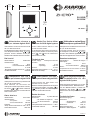 1
1
-
 2
2
-
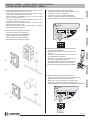 3
3
-
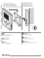 4
4
-
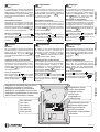 5
5
-
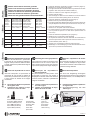 6
6
-
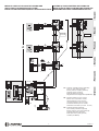 7
7
-
 8
8
-
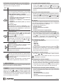 9
9
-
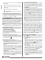 10
10
-
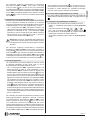 11
11
-
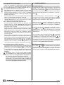 12
12
-
 13
13
-
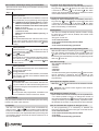 14
14
-
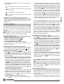 15
15
-
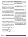 16
16
-
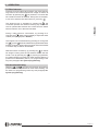 17
17
-
 18
18
-
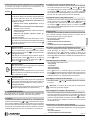 19
19
-
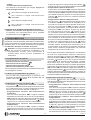 20
20
-
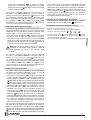 21
21
-
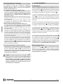 22
22
-
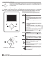 23
23
-
 24
24
-
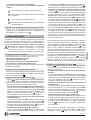 25
25
-
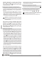 26
26
-
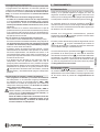 27
27
-
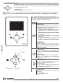 28
28
-
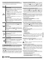 29
29
-
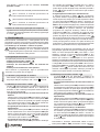 30
30
-
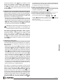 31
31
-
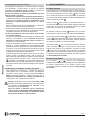 32
32
-
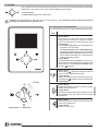 33
33
-
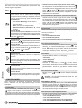 34
34
-
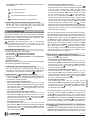 35
35
-
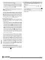 36
36
-
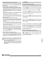 37
37
-
 38
38
-
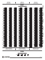 39
39
-
 40
40


ACI Farfisa ZH1252W / ZH1252B Le manuel du propriétaire
- Taper
- Le manuel du propriétaire
dans d''autres langues
- italiano: ACI Farfisa ZH1252W / ZH1252B Manuale del proprietario
- English: ACI Farfisa ZH1252W / ZH1252B Owner's manual
- español: ACI Farfisa ZH1252W / ZH1252B El manual del propietario
- Deutsch: ACI Farfisa ZH1252W / ZH1252B Bedienungsanleitung
- português: ACI Farfisa ZH1252W / ZH1252B Manual do proprietário
Documents connexes
-
ACI Farfisa ZH1262W / ZH1262B Le manuel du propriétaire
-
ACI Farfisa ML2002C Le manuel du propriétaire
-
-
-
-
-
-
-
-

