Peerless ESA763PU Guide d'installation
- Catégorie
- Supports muraux à panneau plat
- Taper
- Guide d'installation

ISSUED: 01-05-11 SHEET #: 061-9062-7 03-22-12
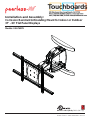
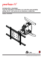
Models: ESA763PU
Installation and Assembly:
Corrosion Resistant Articulating Mount for Indoor or Outdoor
37" - 63" Flat Panel Displays
2300 White Oak Circle • Aurora, Il 60502 • (800) 865-2112 • Fax: (800) 359-6500 • www.peerless-av.com
Max UL Load Capacity: 200 lb (90.7 kg)

2 of 50 ISSUED: 01-05-11 SHEET #: 061-9062-7 03-22-12
Note: Read entire instruction sheet before you start installation and assembly.
Table of Contents
Parts List.............................................................................................................................................................................3, 4
Wall installation ...................................................................................................................................................................6, 7
Installing Adapter Brackets to Display ...............................................................................................................................8-13
Mounting Flat Panel Display .................................................................................................................................................14
Cable Management ..............................................................................................................................................................16
Tools Needed for Assembly
• stud fi nder ("edge to edge" stud fi nder is recommended)
• phillips screwdriver
• drill
• 3/16" (5mm) drill bits for wood studs, 13/32" (10mm) drill bits for concrete
• level
• Do not begin to install your Peerless product until you have read and understood the instructions and warnings
contained in this Installation Sheet. If you have any questions regarding any of the instructions or warnings, for US
customers please call Peerless customer care at 1-800-865-2112, for all international customers, please contact
your local distributor.
• This product should only be installed by someone of good mechanical aptitude, has experience with basic building
construction, and fully understands these instructions.
• Due to outdoor environmental conditions such as heavy snow, hail, rain, etc. the environmental mount and
hardware must be inspected at least once a year. This product should not be exposed to high winds. A qualifi ed
installer or inspector must check for signs of rust, loose fasteners, bent metal, etc. If evidence of excessive wear,
deterioration or any unsafe condition is observed, this product must be taken out of service immediately. Direct all
inquiries to customer care if you have any questions.
• Make sure that the supporting surface will safely support the combined load of the equipment and all attached
hardware and components.
• Never exceed the Maximum UL Load Capacity. See page one.
• If mounting to wood wall studs, make sure that mounting screws are anchored into the center of the studs. Use of
an "edge to edge" stud fi nder is highly recommended.
• Always use an assistant or mechanical lifting equipment to safely lift and position equipment.
• Tighten screws fi rmly, but do not overtighten. Overtightening can damage the items, greatly reducing their holding
power.
• This product was designed to be installed on the following wall construction only;
WALL CONSTRUCTION HARDWARE REQUIRED
• Wood Stud Included
• Wood Beam Included
• Solid Concrete Included
• Cinder Block Included
•Metal Stud Contact Qualifi ed Professional (not evaluated by UL)
•Brick Contact Qualifi ed Professional (not evaluated by UL)
•Other or unsure? Contact Qualifi ed Professional
WARNING

3 of 50 ISSUED: 01-05-11 SHEET #: 061-9062-7 03-22-12
ESA763PU
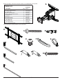
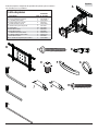
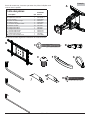
Description Qty. Part #
A
wall arm assembly 1 095-T1994
Buniversal adapter bracket 1 095-T1635-2
C3" wood screw 3 520-D1243
D10mm concrete anchor 4 590-0321
EM10 x 15mm socket head screw 2520-D1262
Fwall plate cover 2590-1325
Gcable ties 16 590-1168
H6mm allen wrench 1 560-9716
I5mm allen wrench 1 560-9640
Jrear cable cover 4 590-P1326
K
front cable cover 4 590-P1327
L5/32" allen wrench 1 560-9646
M2.5" security wood screw 1 520-D1668
Parts List
BCD
EG
M
H
J
L
F
K
I
A
Parts may appear slightly different than illustrated.
Before you begin, make sure all parts shown are included with your product.

4 of 50 ISSUED: 01-05-11 SHEET #: 061-9062-7 03-22-12
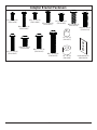
Adapter Bracket Fasteners
M4 x 12 mm (6)
(510-D1079)
M4 x 25 mm (4)
(510-D1082)
M5 x 12 mm (4)
(520-D1064) M5 x 25 mm (4)
(520-D1122)
M8 x 12 mm (6)
(520-D1068)
M8 x 40 mm (4)
(520-D1152)
M8 x 25 mm (4)
(520-D1101)
I.D. .34" (4)
(540-1059)
I.D. .22" (4)
(540-1057)
M6 x 30 mm (4)
(520-D1067)
M6 x 12 mm (4)
(520-D1050)
M6 x 25 mm (4)
(520-D1211)
M6 x 20 mm (4)
(520-D1554)
multi-washer (6)
(580-D1036)

5 of 50 ISSUED: 01-05-11 SHEET #: 061-9062-7 03-22-12
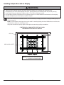
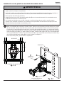
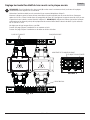
1/4-20 X 17 MM SCREWS WALL PLATE
WALL ARM
SLIDE PLATE
WALL PLATE RAIL
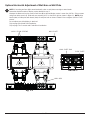
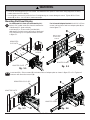
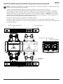
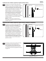
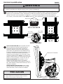
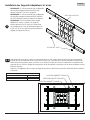
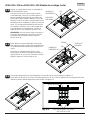
NOTE: If mounting wall arm (A) to wood stud walls, slots on wall plate must align to wood studs.
Determine desired location of display center detailed in step 2.
Measure the distance from the center of wall arm (A) to desired display center. Loosen four 1/4-20 x 17mm screws
using 5mm allen wrench (I). Slide wall arm assembly 4-1/2" to the left or right as shown in fi gure 1.1. NOTE: Align
bevels (dots) of slide plate with bevels (dots) of wall plate rails as shown in detail 1 then retighten 1/4-20 x 17mm
screws.
Do not adjust arm while display is attached.
Skip to page 6 for Wood Stud Installation.
Skip to page 7 for Concrete and Cinder Block Installation.
1
Optional Horizontal Adjustment of Wall Arm on Wall Plate
fi g. 1.1
DETAIL 1

6 of 50 ISSUED: 01-05-11 SHEET #: 061-9062-7 03-22-12
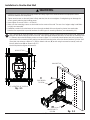
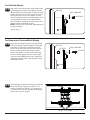
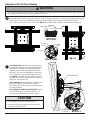
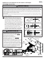
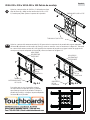
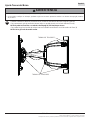
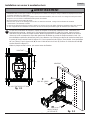
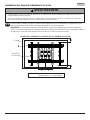
9"
(229 mm)
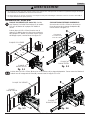
Use a stud fi nder to locate the edges of the studs and draw a vertical line down the center of each stud. Determine
and mark the desired display center on the wall. Place wall plate template (wall arm) on wall with top mounting slots
9" (229mm) above desired display center as shown in fi gure 2.1. Level wall plate template (wall arm) on wall and
mark center of four mounting holes making sure that the mounting holes are on the stud centerlines. Drill four 3/16"
(5mm) dia. pilot holes to a depth of 3" (76mm). Attach wall arm (A) to wall using three wood screws (C) and one
security wood screw (M) as shown in fi g. 2.2.
Level wall plate then tighten all fasteners.
Installation to Double-Stud Wall
2
• Installer must verify that the supporting surface will safely support the combined load of the equipment and all
attached hardware and components.
• Tighten wood screws so that wall plate is fi rmly attached, but do not overtighten. Overtightening can damage the
screws, greatly reducing their holding power.
• Never tighten in excess of 80 in. • lb (9 N.M.).
• Make sure that mounting screws are anchored into the center of the stud. The use of an "edge to edge" stud fi nder
is highly recommended.
• Hardware provided is for attachment of mount through standard thickness drywall or plaster into wood studs.
Installers are responsible to provide hardware for other types of mounting situations (not evaluated by UL).
WARNING
A
WOOD STUD
WOOD STUD
fi g. 2.2
CS = CENTER OF DISPLAY
fi g. 2.1
CS
M
C
#14 SECURITY
SCREW
5/16" WOOD
SCREW

7 of 50 ISSUED: 01-05-11 SHEET #: 061-9062-7 03-22-12
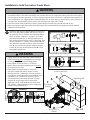
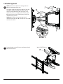
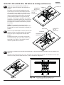
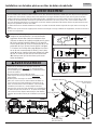
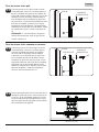
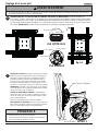
Installation to Solid Concrete or Cinder Block
Determine and mark the desired display center on the
wall. Place wall plate template (wall arm) on wall with
top mounting slots 9" (229mm) above desired display
center as shown in fi gure 2.1 on page 6. Level wall
plate template (wall arm) on wall and mark center of
four mounting holes. Drill four 13/32" (10mm) dia. pilot
holes to a depth of 3" (76mm). Insert anchors (D) into
four holes fl ush with wall as shown (right). Place wall
arm (A) over anchors and secure using three wood
screws (C) and one security wood screw (M). Level,
then tighten all fasteners.
D
2
2
A
fi g. 2.3
M
C
• When installing Peerless wall mounts on cinder block, verify that you have a minimum of 1-3/8" (35mm) of actual
concrete thickness in the hole to be used for the concrete anchors. Do not drill into mortar joints! Be sure to mount
in a solid part of the block, generally 1" (25mm) minimum from the side of the block. Cinder block must meet ASTM
C-90 specifi cations. It is suggested that a standard electric drill on slow setting is used to drill the hole instead of a
hammer drill to avoid breaking out the back of the hole when entering a void or cavity.
• Concrete must be 2000 psi density minimum. Lighter density concrete may not hold concrete anchor.
• Make sure that the supporting surface will safely support the combined load of the equipment and all attached
hardware and components.
WARNING
• Tighten screws so that wall plate is fi rmly attached,
but do not overtighten. Overtightening can damage
screws, greatly reducing their holding power.
• Never tighten in excess of 80 in. • lb (9 N.M.).
• Always attach concrete expansion anchors directly
to load-bearing concrete.
• Never attach concrete expansion anchors to
concrete covered with plaster, drywall, or other
fi nishing material. If mounting to concrete surfaces
covered with a fi nishing surface is unavoidable (not
evaluated by UL), the fi nishing surface must be
counterbored as shown below. Be sure concrete
anchors do not pull away from concrete when
tightening screws. If plaster/drywall is thicker than
5/8" (16mm), custom fasteners must be supplied by
installer (not evaluated by UL).
WARNING
SOLID CONCRETE
CINDER BLOCK
CUTAWAY VIEW
INCORRECT CORRECT
wall
plate wall
plate
plaster/
dry wall plaster/
dry wall
concrete concrete
1
3
2
D
Drill holes and insert anchors (D).
Place plate (A) over anchors (D) and secure with screws (C,M).
Tighten all fasteners.
A
D
C,M
concrete
surface
#14 SECURITY
SCREW
5/16" WOOD
SCREW

8 of 50 ISSUED: 01-05-11 SHEET #: 061-9062-7 03-22-12
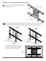
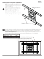
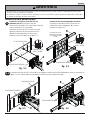
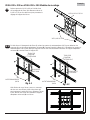
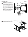
NOTE: If display has a VESA 400 horizontal
mounting pattern, skip to step 3-3 or 3-4 on page
10.
NOTE: For VESA 200x200 or VESA 200x100
mount hole patterns, skip to step 4 on page 11.
NOTE: For dedicated PLP plate installation skip to
step 5 on page 13.
Remove four 1/4-20 x .6" screws using 5 mm allen
wrench (I) and loosen two 1/4-20 x 1.25" screws
1/2 turn to allow for display bracket adjustment.
1/4-20 x .6" SCREWS
1/4-20 x 1.25" SCREWS
3
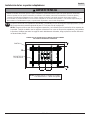
To prevent scratching the display, set a cloth on a fl at, level surface that will support the weight of the display.
Place display face side down and refer to display manufacturers instructions for removing obstructions from the
back of the display. Adjust display brackets to align with display mounting holes.
Measure horizontal mounting hole pattern and choose fi xed stop-position from chart below.
3-1
FIXED STOP-POSTION #2
FIXED STOP-POSTION #1
FIXED STOP-POSTION #3
horizontal mounting hole pattern fixed stop-position
10-3/4" - 16-1/16" (273 - 408 mm) #1
15-1/16" - 21-9/16" (383 - 548 mm) #2
20-7/16" - 27-9/16" (519 - 700 mm) #3
Installing Adapter Brackets to Display

9 of 50 ISSUED: 01-05-11 SHEET #: 061-9062-7 03-22-12
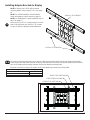
Select the screws from the baffl ed fastener pack that best fi t your display and secure to display following step 3-3
or 3-4 on page 10.
NOTE: Top and bottom mounting holes must be used for attaching display brackets. Middle holes should also be
used where the fasteners and displays allow.
Verify that all holes are properly aligned, then tighten screws using a phillips screwdriver.
CENTER DISPLAY BRACKETS VERTICALLY AND
HORIZONTALLY ON BACK OF DISPLAY
DISPLAY
DISPLAY BRACKETS
NOTE: "X" dimensions should be equal.
"Y" dimensions should be equal.
• Tighten screws so display brackets are fi rmly attached to display. Do not tighten with excessive force.
Overtightening can cause stress damage to screws, greatly reducing their holding power and possibly causing
screw heads to become detached. Tighten to 40 in. • lb (4.5 N.M.) maximum torque.
• If screws don't get three complete turns in the display inserts or if screws bottom out and bracket is still not tightly
secured, damage may occur to display or product may fail.
WARNING
YY
X
X
Installing Adapter Brackets to Display
3-2

10 of 50 ISSUED: 01-05-11 SHEET #: 061-9062-7 03-22-12
Begin with the shortest length screw, hand thread
screw through multi-washer and display brackets
(B) into display as shown below. Screw must make
at least three full turns into the mounting hole and
fi t snug into place. Do not over tighten. If screw
cannot make three full turns into the display, select
a longer length screw from the baffl ed fastener
pack. Repeat for remaining mounting holes, level
display brackets and tighten screws.
NOTE: Spacers may not be used, depending upon
the type of display.
Skip to step 3-5.
Begin with the longest length screw, hand thread
screw through multi-washer, display brackets (B)
and spacer in that order into display as shown
below. Screw must make at least three full turns
into the mounting hole and fi t snug into place.
Do not over tighten. If screw cannot make three
full turns into the display, select a shorter length
screw from the baffl ed fastener pack. Repeat for
remaining mounting holes, level display brackets
and tighten screws.
For Flat Back Display
For Bump-out or Recessed Back Display
3-3
3-4
DISPLAY MULTI-WASHER
SCREW
B
DISPLAY MULTI-WASHER
SPACER
B
SCREW
Center display brackets horizontally and vertically
on back of display. Tighten two 1/4-20 x 1.25"
screws. Reinstall four 1/4-20 x .6" screws using
5 mm allen wrench (I) into appropriate fi xed-stop
position from chart on page 8.
3-5 1/4-20 x 1.25" SCREWS
1/4-20 x .6" SCREWS

11 of 50 ISSUED: 01-05-11 SHEET #: 061-9062-7 03-22-12
Remove four 1/4-20 x .6" screws using 5mm allen wrench
(I) and loosen two 1/4-20 x 1.25" screws 1/2 turn to allow for
display bracket adjustment.
Remove four 1/4-20 self tapping screws to detach display brackets from outer mount holes of universal adapter
bracket (B) using 5mm allen wrench (I) as shown in fi gure 4.1. Reinstall four 1/4-20 self tapping screws to secure
display brackets to inner set of mounting holes on universal adapter bracket (B) as shown in fi gure 4.2.
1/4-20 SELF
TAPPING SCREWS 1/4-20 SELF
TAPPING SCREWS
DISPLAY
BRACKETS DISPLAY
BRACKETS
INNER
MOUNTING
HOLES
OUTER
MOUNTING
HOLES
fi g. 4.1 fi g. 4.2
VESA 200 x 200 or VESA 200 x 100 Mounting Pattern
To prevent scratching the display, set a cloth on a
fl at, level surface that will support the weight of the
display. Place display face side down and place
universal adapter bracket (B) onto display.
4-1
4
BB
B
1/4-20 x .6" SCREWS
1/4-20 x 1.25" SCREWS

12 of 50 ISSUED: 01-05-11 SHEET #: 061-9062-7 03-22-12
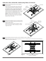
Slide universal adapter bracket to the opposite side
and align second display bracket with second set of
display mounting holes.
Hand thread screws through multi-washer, display
bracket, and spacer if used, into display as shown.
Tighten all screws.
4-3
SCREW
MULTI-WASHER
MULTI-
WASHER
DISPLAY DISPLAY
BRACKET
VESA 200 x 200 or VESA 200 x 100 Mounting Pattern (Continued)
Align one display bracket with one set of display
mounting holes.
Begin with the shortest length screw, hand thread
screw through multi-washer and display brackets
into display as shown. Screw must make at least
three full turns into the mounting hole and fi t snug
into place. Do not over tighten. If screw cannot
make three full turns into the display, select a longer
length screw from the baffl ed fastener pack. Center
display brackets vertically and tighten screws.
NOTE: For displays with a bump-out or recessed
back, spacer may be used. Spacer goes between
display bracket and display.
4-2 SCREW DISPLAY
DISPLAY
BRACKET
Center display brackets horizontally on back of display as shown in fi gure 4.3.
Tighten two 1/4-20 x 1.25" screws. Reinstall four 1/4-20 x .6" screws using 5 mm allen wrench (I) into fi xed-stop
position 1 as shown in fi gure 4.4.
4-4
fi g. 4.4
1/4-20 x 1.25" SCREWS
FIXED STOP POSITION #1 WITH
1/4-20 x .6" SCREWS
fi g. 4.3

13 of 50 ISSUED: 01-05-11 SHEET #: 061-9062-7 03-22-12
• Do not lift more weight than you can handle. Use additional man power or mechanical lifting equipment to safely
handle placement of the display.
• Do not tighten screws with excessive force. Overtightening can cause damage to mount. Tighten M10 x 15mm
screws (E) to 40 in. • lb (4.52 N.M.) maximum torque.
WARNING
For Dedicated PLP Plate (not evaluated by UL):
Refer to PLP model instruction sheet for attachment
of dedicated PLP plate to display.
Install two M10 x 15mm screws (provided with
dedicated PLP plate) into top two holes of dedicated
PLP plate leaving 1/4" of exposed thread as shown
in fi gure 5.1.
Insert two M10 x 15mm screws (E) into bottom holes of adapter plate as shown in fi gure 5.3 or 5.4. Tighten all
fasteners with 6mm allen wrench (H).
5-1
Mounting Flat Panel Display
5For Universal Adapter Bracket: Hook M10 x 15mm
screws into keyslots of wall arm adapter plate (A) as
shown fi gure 5.2.
A
A
DEDICATED
PLP PLATE
ADAPTER PLATE ADAPTER PLATE
M10 X 15 MM
SCREW
1/4" M10 X 15 MM
SCREW
1/4"
fi g. 5.1 fi g. 5.2
fi g. 5.3 fi g. 5.4
EE
DEDICATED PLP PLATE
ADAPTER PLATE
ADAPTER PLATE
DISPLAY NOT
SHOWN FOR
CLARITY
B
B

14 of 50 ISSUED: 01-05-11 SHEET #: 061-9062-7 03-22-12
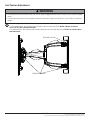
TILT Adjustment: Adjust tension knob on side of
mount to desired tension to enable tilt adjustment
and balance your display size and weight. Push
or pull from top or bottom of display to adjust tilt
as shown. The tilt can be adjusted to a maximum
of 10° forward or 5° backward. Retighten tension
knob.NOTE: For larger displays, tension screw on
opposite side of mount may need to be tightened
using 5/32" allen wrench (L).
ROLL Adjustment: Rotate display 5° clockwise or
counter-clockwise, level display then tighten
M5 x 10mm roll screws using 5mm allen wrench (I)
as shown in detail 2.
FOR VERTICAL HEIGHT ADJUSTMENT: Tighten
or loosen M8 x 40mm screw to achieve ± 1" of
vertical height adjustment as shown in detail 2.
7
• Do not tighten screws with excessive force.
• Be careful not to pinch fi ngers when opening and
closing mount from the wall.
CAUTION
TENSION KNOB
DETAIL 2
M5 X 10MM
SCREWS
M8 X 40MM
SCREW
Adjustment of Flat Panel Display
6
• M10 x 15mm screws (E) must be securly tightened before changing orientation of wall arm assembly (A). Failure to
lock adapter bracket can cause display to come off of mount.
WARNING
fi g. 6.1
FOR PORTRAIT OR LANDSCAPE DISPLAY ORIENTATION: Remove two M5 x 12mm screws, one M5 x 6mm
screw and rotation block from top of tilt head as shown in top view and rear view. Gently grasp sides of display and
rotate display into portrait or landscape position as shown in fi gure 6.1 and reinstall rotation block with two
M5 x 12mm screws and one M5 x 6mm screw. NOTE: M5 x 6mm screw required in landscape orientation only.
REAR VIEW
TOP VIEW
ROTATION BLOCK
ROTATION BLOCK
M5 X 12MM SCREWS
M5 X 6MM SCREWS
M5 X 12MM
SCREWS
M5 X 6MM
SCREWS

15 of 50 ISSUED: 01-05-11 SHEET #: 061-9062-7 03-22-12
KJ
A
GCABLE
DETAIL 3
SLOT
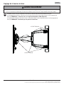
Cable Management
NOTE: Make sure cables have enough slack to
allow full movement of the arm.
Run power cable through top or bottom of arm (A)
and signal cable(s) through other side of arm in
order to avoid interference with the signal. Lock
cables into place by snapping cable covers (J &
K) onto mount as shown. Display may have to be
moved for easy access.
Optional: If additional cable management is
required route cable ties (G) through slots of arm (A)
as shown in detail 3.
8
Snap wall plate covers (F) to top and bottom of wall
plate rails as shown.
9F
WALL PLATE RAIL

16 of 50 ISSUED: 01-05-11 SHEET #: 061-9062-7 03-22-12
If more or less tension is desired in the arm pivot points, do the following:
• To increase tension, turn socket screw clockwise with 5mm allen wrench (I). NOTE: Tighten screws to
50 in • lbs (5.6 N.m.) maximum torque.
• To reduce tension, turn socket screw counter-clockwise with 5mm allen wrench (I). NOTE: Do not turn more
than half a turn.
10
• Do not remove screw or loosen screw until it is no longer engaged with the mount. Doing so may cause the display
to fall.
• If screws become loose over time, tighten screws as necessary. Tighten screws to 50 in • lbs (5.6 N.m.) maximum
torque.
WARNING
TENSION SCREWS
TENSION SCREW
Arm Tension Adjustment
© 2012, Peerless Industries, Inc. All rights reserved.
All other brand and product names are trademarks or registered trademarks of their respective owners.

Modelos: ESA763PU
Instalación y montaje:
Soporte articulador resistente a la corrosión para pantallas
planas de 37" a 63" para uso en interiores y exteriores
2300 White Oak Circle • Aurora, Il 60502 • (800) 865-2112 • Fax: (800) 359-6500 • www.peerless-av.com
PUBLICADO: 01-05-11 HOJA #: 061-9062-7 03-22-12
Màxima capcaidad de carga: 200 lb (90.7 kg)

18 de 50 PUBLICADO: 01-05-11 HOJA #: 061-9062-7 03-22-12
Español
• No comience a instalar su producto de Peerless hasta haber leído y entendido las instrucciones y las advertencias
contenidas en la Hoja de Instalación. Si tiene alguna pregunta acerca de cualquiera de las instrucciones o las
advertencias, por favor, llame a Servicio al Cliente de Peerless al 1-800-865-2112 si está en EE. UU. Si es un cliente
internacional, por favor, comuníquese con su distribuidor local.
• Este producto sólo debe ser instalado por una persona que tenga una buena aptitud mecánica, que tenga
experiencia en construcción básica de edifi cios y que entienda estas instrucciones en su totalidad.
• Debido a condiciones ambientales, como grandes cantidades de nieve, granizo, lluvia, etc., el soporte y los
accesorios se tienen que inspeccionar, por lo menos, una vez al año. Este producto no debe estar expuesto a fuertes
vientos. Un instalador o inspector califi cado debe revisar el soporte para detectar señales de oxidación, sujetadores
sueltos, metales doblados, etc. Si se detectan señales de desgaste excesivo, deterioro o cualquier condición que no
sea segura, se debe descontinuar el uso del producto de inmediato. Dirija todas sus preguntas a Servicio al Cliente,
si tiene alguna.
• Asegúrese de que la superfi cie de apoyo sostendrá, con seguridad, la carga combinada del equipo y todos los
fi jadores y componentes.
• Nunca sobrepase la capacidad máxima de soportar carga aceptada por Underwriters Laboratories. Vea la página 17.
• Si va a instalar el producto en una pared con montantes de madera, asegúrese de que los tornillos de montaje estén
anclados en el centro de los montantes. Se recomienda utilizar un localizador de montantes de "borde a borde".
• Siempre cuente con la ayuda de un asistente o utilice un equipo mecánico de izar para levantar y colocar el equipo
con más seguridad.
• Apriete los tornillos con fi rmeza, pero no en exceso. Apretarlos en exceso puede dañar los artículos y puede
disminuir signifi cativamente su fuerza de fi jación.
• Este producto fue diseñado para ser instalado en paredes con la siguiente construcción solamente:
CONSTRUCCIÓN DE LA PARED ACCESORIOS NECESARIOS
• Montante de madera Incluido
• Viga de madera Incluido
• Concreto macizo Incluido
• Bloque de hormigón de escorias Incluido
• Montante de metal No lo instale excepto con el juego de accesorios de Peerless para
montantes de metal (no evaluados por UL)
• Ladrillo Comuníquese con un profesional califi cado (no evaluados por UL)
• ¿Otra superfi cie o no está seguro? Comuníquese con un profesional califi cado
ADVERTENCIA
NOTA: Lea la hoja de instrucciones completa antes de comenzar la instalación y el ensamblaje.
Herramientas necesarias para el ensamblaje
• localizador de montantes (se recomienda uno de "borde a borde")
•destornillador phillips
•taladro
•broca de 13/32" (10 mm) para paredes de concreto y de bloque de hormigón de escorias, broca de 3/16" (5 mm) para
paredes con montantes de madera
•nivel
Tabla de Contenido
Lista de piezas................................................................................................................................................................19, 20
Instalación en una pared ................................................................................................................................................22, 23
Instalación del soporte adaptador universal ....................................................................................................................24-28
Instalación de la pantalla plana ............................................................................................................................................29
Manejo de los cables ............................................................................................................................................................32

19 de 50 PUBLICADO: 01-05-11 HOJA #: 061-9062-7 03-22-12
Español
Las piezas pueden verse un poco distintas a la ilustración.
Antes de empezar, asegúrese de que todas las piezas que se muestran
son incluidos con su producto.
BCD
EG
M
H
J
L
F
K
I
A
ESA763PU
Descripción Cant. N° de pieza
A
brazo de pared 1 095-T1994
Bsoporte adaptador universal 1 095-T1635-2
C3" tornillos para madera 3 520-D1243
D10mm anclajes de concreto 4 590-0321
Etornillos de M10 x 15mm 2520-D1262
Fcubiertas de la placa de pared 2590-1325
Gsujetacables 16 590-1168
Hllave allen de 6mm 1 560-9716
Illave allen de 5mm 1 560-9640
JCubierta trasera para cables 4 590-P1326
K
Cubierta delantera para cables 4 590-P1327
Lllave allen de 5/32" 1 560-9646
M2.5" tornillo de seguridad para madera 1 520-D1668
Lista de piezas

20 de 50 PUBLICADO: 01-05-11 HOJA #: 061-9062-7 03-22-12
Español
M4 x 12 mm (6)
(510-D1079)
M4 x 25 mm (4)
(510-D1082)
M5 x 12 mm (4)
(520-D1064) M5 x 25 mm (4)
(520-D1122)
M8 x 12 mm (6)
(520-D1068)
M8 x 40 mm (4)
(520-D1152)
M8 x 25 mm (4)
(520-D1101)
I.D. .34" (4)
(540-1059)
I.D. .22" (4)
(540-1057)
M6 x 30 mm (4)
(520-D1067)
M6 x 12 mm (4)
(520-D1050)
M6 x 25 mm (4)
(520-D1211)
M6 x 20 mm (4)
(520-D1554)
Fijaciones para los soportes adaptadores
arandela
múltiple (6)
(580-1036)
La page est en cours de chargement...
La page est en cours de chargement...
La page est en cours de chargement...
La page est en cours de chargement...
La page est en cours de chargement...
La page est en cours de chargement...
La page est en cours de chargement...
La page est en cours de chargement...
La page est en cours de chargement...
La page est en cours de chargement...
La page est en cours de chargement...
La page est en cours de chargement...
La page est en cours de chargement...
La page est en cours de chargement...
La page est en cours de chargement...
La page est en cours de chargement...
La page est en cours de chargement...
La page est en cours de chargement...
La page est en cours de chargement...
La page est en cours de chargement...
La page est en cours de chargement...
La page est en cours de chargement...
La page est en cours de chargement...
La page est en cours de chargement...
La page est en cours de chargement...
La page est en cours de chargement...
La page est en cours de chargement...
La page est en cours de chargement...
La page est en cours de chargement...
La page est en cours de chargement...
-
 1
1
-
 2
2
-
 3
3
-
 4
4
-
 5
5
-
 6
6
-
 7
7
-
 8
8
-
 9
9
-
 10
10
-
 11
11
-
 12
12
-
 13
13
-
 14
14
-
 15
15
-
 16
16
-
 17
17
-
 18
18
-
 19
19
-
 20
20
-
 21
21
-
 22
22
-
 23
23
-
 24
24
-
 25
25
-
 26
26
-
 27
27
-
 28
28
-
 29
29
-
 30
30
-
 31
31
-
 32
32
-
 33
33
-
 34
34
-
 35
35
-
 36
36
-
 37
37
-
 38
38
-
 39
39
-
 40
40
-
 41
41
-
 42
42
-
 43
43
-
 44
44
-
 45
45
-
 46
46
-
 47
47
-
 48
48
-
 49
49
-
 50
50


Peerless ESA763PU Guide d'installation
- Catégorie
- Supports muraux à panneau plat
- Taper
- Guide d'installation
dans d''autres langues
- English: Peerless ESA763PU Installation guide
- español: Peerless ESA763PU Guía de instalación
Documents connexes
-
Peerless SA771P spécification
-
-
-
-
-
-
-
-
-
