Schneider Electric EVlink Pro AC Instruction Sheet
- Taper
- Instruction Sheet

Main GPS DIV ANT
Q3240A1-1
EVA1Mp
EVlink™ - EVA1MS / EVA1MM
GEX5945401-01
04/2023
1/16
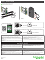
Modem 4G embarqué pour EVlink Pro AC
Embedded 4G Modem for EVlink Pro AC
fr
en
EVA1MS EVA1MM
RISQUE D'ÉLECTROCUTION, D'EXPLOSION OU D'ÉCLAIR D'ARC ÉLECTRIQUE
p Coupez l’alimentation complète de la borne de charge avant toute intervention sur
celle-ci.
p Utilisez un testeur de tension présentant les caractéristiques nominales appropriées.
Si ces directives ne sont pas respectées, cela entraînera la mort ou des blessures
graves.
HAZARD OF ELECTRIC SHOCK, EXPLOSION OR ARC FLASH
p Turn off all power supplying the charging station before working on the charging station.
p Use a voltage tester of appropriate rating.
Failure to follow these instructions will result in death or serious injury.
DANGER / DANGER
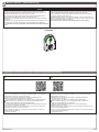
RISQUE D’INTERFÉRENCE RADIO
p En fonctionnement le modem peut émettre des signaux électromagnétiques
susceptibles d’interférer avec différents systèmes embarqués.
p N’utilisez pas le modem dans des zones où l’utilisation de communications mobiles est
limitée ou interdite.
Si ces directives ne sont pas respectées, cela peut entraîner des dommages
matériels.
RISK OF RADIO INTERFERENCE
p In operation, the modem may emit electromagnetic signals that can interfere with
different embedded systems.
p Do not use the modem in areas where the use of mobile communications is limited or
prohibited.
Failure to follow these instructions can result in equipment damage.
AVIS / NOTICE
REMARQUE IMPORTANTE
p Cet équipement doit être installé et entretenu par un électricien qualifié.
p Toutes les normes et réglementations de sécurité locales, nationales et régionales
applicables doivent être respectées lors de l’installation et de l’utilisation de cet
équipement.
p Le fabricant décline toute responsabilité en cas de non-respect des instructions fournies
dans la présente fiche.
p L’usage du modem ne peut se faire que si la couverture du réseau GSM est assurée
par l’opérateur.
PLEASE NOTE
p This device must be installed and serviced by a qualified electrician.
p All applicable local, regional and national safety standards and regulations must be
complied with during the installation and use of this device.
p The manufacturer disclaims all liability in the event of non-compliance with the
instructions on this sheet.
p The modem can only be used if GSM network coverage is provided by the operator.
Customer Care Center
x2 x2
Main GPS DIV ANT
Q3240A1-1
EVA1Mp
https://www.youtube.com/watch?v=XZlwfECY5pE
https://www.youtube.com/watch?v=xoO-q_HU-h8&t=97s
Configuration du modem avec eSetup / Modem Configuration With eSetup
Installation du modem / Modem Installation

GEX5945401-012/16
Pour EAV1MM uniquement
For EVA1MM only
AVIS / NOTICE
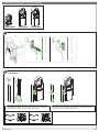
Nécessaire pour l’installation / Required for Installation
1Contenu / Content
T6
Ø13 mm
eSetup app - Apple storeeSetup app - Google store
Carte SIM micro
Micro SIM card
Main GPS DIV ANT
Q3240A1-1
Main GPS DIV ANT
Q3240A1-1
EVA1MS EVA1MM
RISQUE DE DÉCHARGE ÉLECTROSTATIQUE OU DE SURTENSION
p Ne touchez pas les cartes électroniques.
p Utilisez des protections antistatiques lors des opérations de raccordement à l’intérieur
de la borne de charge.
Si ces directives ne sont pas respectées, cela peut entraîner des dommages
matériels.
HAZARD OF ELECTROSTATIC DISCHARGE OR POWER
SURGE
p Do not touch the electronic boards.
p Use anti-static protection when making connection operations inside the charging
station.
Failure to follow these instructions can result in equipment damage.
GEX5945402 GEX5945402
REMARQUE IMPORTANTE
p Les modems EVA1MS et EVA1MM fonctionnent avec une version de logiciel de la
borne de charge 1.2.1 ou plus (utiliser eSetup pour connaître la version logiciel
de votre borne de charge).
p Pour une borne de charge présentant une version de logiciel antérieure, mettez à jour
la version du logiciel avec eSetup.
PLEASE NOTE
p The modems EVA1MS and EVA1MM are compatible with charging station software
version 1.2.1 or higher (use eSetup to find the software version of your charging station).
p For a charging station with an earlier software version, update the software by using
eSetup.

3/16GEX5945401-01
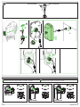
Connexion en chaînage / Daisy Chain
p p p
y 10
Pour réaliser une connexion en chaînage des bornes de charge, consultez la
notice de montage NNZ1940301.
fr To make a daisy chain connection of the charging stations , consult the instruction
sheet NNZ1940301.
en
p L’installation d’un modem 4G dans une des bornes permet une communication 4G
jusqu’à 10 bornes.
p Pour la mise en service du groupe de bornes de charge, consultez le chapitre 6.
fr p The installation of a 4G modem in one charging station allows communication with
up to 10 charging stations.
p For the commissioning of a charging stations cluster, see chapter 6.
en
NNZ1940301
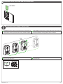
2Installation de la carte SIM / SIM Card Installation
Carte SIM micro
Micro SIM card
modem 4G

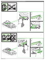
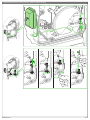
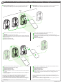
3.3 Installation de l’antenne principale / Main Antenna Installation
3.2 Installation du modem / Modem Installation
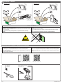
3.1 Démontage du capot de la face avant / Remove Front Cover
3Installation du modem EVA1MS / Modem EVA1MS Installation
Pour démonter le capot de la face avant de la borne de charge Evlink Pro AC,
consultez la notice de montage NNZ1940301.
fr To remove the front cover of the Evlink Pro AC charging station, consult the
instruction sheet NNZ1940301.
en
NNZ1940301
2
GPS
Q3240A1-1
DIV ANT
GPS
Q3240A1-1
DIV ANT
GPS
Q3240A1-1
DIV ANT
1
2
GPS
Q3240A1-1
DIV ANT
x2 T6
1
Essuyez la surface avec un chiffon sec
Wipe surface with a dry cloth
2
3
AVIS / NOTICE
RISQUE DE DÉTÉRIORATION DU MODEM
Prenez toutes les précautions nécessaires pour la manipulation et l’installation du
modem dans le connecteur de la carte mère.
Si ces directives ne sont pas respectées, cela peut entraîner des dommages
matériels.
HAZARD OF MODEM DAMAGE
Take all necessary precautions when handling and installing the modem in the connector
on the motherboard.
Failure to follow these instructions can result in equipment damage.
3
0.25 N•m
2.2 lb-in.
4/16 GEX5945401-01

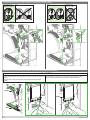
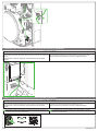
3.4 Installation de l’antenne diversité / Diversity Antenna Installation
2
1
Essuyez la surface avec un chiffon sec
Wipe surface with a dry cloth
3
Essuyez la surface avec un chiffon sec
Wipe surface with a dry cloth
2
Câble attaché T2
Attached T2 cable
T2S
Câble attaché T2
Attached T2 cable
T2S
1
3
5/16GEX5945401-01

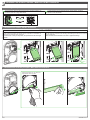
3.6 Connexion des antennes au modem / Connecting Antennas to the Modem
AVIS / NOTICE
RISQUE DE DÉTÉRIORATION DU MODEM
Prenez toutes les précautions nécessaires pour raccorder le connecteur de l’antenne sur
le modem.
Si ces directives ne sont pas respectées, cela peut entraîner des dommages
matériels.
HAZARD OF MODEM DAMAGE
Take all necessary precautions to connect the antenna connector to the modem.
Failure to follow these instructions can result in equipment damage.
3.5 Acheminement des fils des antennes / Routing the Antenna Wires
2
GPS
Q3240A1-1
DIV ANT
2
GPS
Q3240A1-1
DIV ANT
Main
Main
Câble attaché T2
Attached T2 cable
T2S Câble attaché T2
Attached T2 cable
T2S
DIV ANT
DIV ANT
1 2
6/16 GEX5945401-01

3.7 Remise en place du capot de la face avant / Reinstall Front Cover
Pour remettre en place le capot de la face avant de la borne de charge Evlink Pro AC,
consultez la notice de montage NNZ1940301.
fr To reinstall the front cover of the Evlink Pro AC charging station, consult the
instruction sheet NNZ1940301.
en
NNZ1940301
AVIS / NOTICE
RISQUE DE DOMMAGES MATÉRIELS
Ne pincez pas les conducteurs électriques lors de la fermeture du capot de la face avant.
Si ces directives ne sont pas respectées, cela peut entraîner des dommages
matériels.
HAZARD OF EQUIPMENT DAMAGE
Be careful not to pinch electrical wires when installing front cover.
Failure to follow these instructions can result in equipment damage.
7/16GEX5945401-01

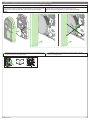
4.3 Installation du modem / Modem Installation
4.1 Démontage du capot de la face avant / Remove Front Cover
4.2 Préparation / Preparation
1
4Installation du modem EVA1MM / Modem EVA1MM Installation
NNZ1940301
AVIS / NOTICE
RISQUE DE DÉTÉRIORATION DU MODEM
Prenez toutes les précautions nécessaires pour la manipulation et l’installation du
modem dans le connecteur de la carte mère.
Si ces directives ne sont pas respectées, cela peut entraîner des dommages
matériels.
HAZARD OF MODEM DAMAGE
Take all necessary precautions when handling and installing the modem in the connector
on the motherboard.
Failure to follow these instructions can result in equipment damage.
Pour démonter le capot de la face avant de la borne de charge Evlink Pro AC,
consultez la notice de montage NNZ1940301.
fr To remove the front cover of the Evlink Pro AC charging station, consult the
instruction sheet NNZ1940301.
en
2
GPS
Q3240A1-1
DIV ANT
GPS
Q3240A1-1
DIV ANT
GPS
Q3240A1-1
DIV ANT
1
2
GPS
Q3240A1-1
DIV ANT
x2 T6
3
0.25 N•m
2.2 lb-in.
8/16 GEX5945401-01
Ø13 mm
2

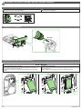
4.4 Installation de l’antenne / Antenna Installation
EVA1RFKS2EVA1RFKS1EVA1RWKS1
EVA1RFKS1
EVA1RFKS2
180°
1 2 3
EVA1RWKS1
21
3
JYT24397JYT24398
L’encoche pour l’installation de l’antenne doit être positionnée en haut de la
plaque latérale, consultez la notice de montage JYT24397 ou JYT24398 pour
retourner la plaque latérale si l’encoche est positionnée en bas.
fr The notch for the installation of the antenna must be positioned at the top of the
side plate. Refer to the instruction sheet JYT24397 or JYT24398 to invert the
side plate if the notch is positioned at the bottom.
en
9/16GEX5945401-01

JYT24399
4.5 Installation d’EVlink Pro AC / EVlink Pro AC Installation
Pour installer la borne de charge Evlink Pro AC dans la structure métallique,
consultez la notice de montage JYT24397, JYT24398 ou JYT24399.
fr To install Evlink Pro AC charging station in the metal enclosure, consult the
instruction sheet JYT24397, JYT24398 or JYT24399.
en
JYT24397JYT24398
EVA1RFKS1 EVA1RFKS2
EVA1RWKS1
6
78
9
3
4
5
Cell connector Wi-Fi connector
2
A
1
5 N•m
44 lb-in.
10/16 GEX5945401-01

4.6 Acheminement du fil de l’antenne / Antenna Wire Routing
11/16GEX5945401-01
1
2
A
3
45
6

4.8 Remise en place du capot de la face avant / Reinstall Front Cover
NNZ1940301
4.7 Connexion de l’antenne au modem / Connecting the Antenna to the Modem
AVIS / NOTICE
RISQUE DE DÉTÉRIORATION DU MODEM
Prenez toutes les précautions nécessaires pour raccorder le connecteur de l’antenne sur
le modem.
Si ces directives ne sont pas respectées, cela peut entraîner des dommages
matériels.
HAZARD OF MODEM DAMAGE
Take all necessary precautions to connect the antenna connector to the modem.
Failure to follow these instructions can result in equipment damage.
Pour remettre en place le capot de la face avant de la borne de charge Evlink Pro AC,
consultez la notice de montage NNZ1940301.
fr To reinstall the front cover of the Evlink Pro AC charging station, consult the
instruction sheet NNZ1940301.
en
AVIS / NOTICE
RISQUE DE DOMMAGES MATÉRIELS
Ne pincez pas les conducteurs électriques lors de la fermeture du capot de la face avant.
Si ces directives ne sont pas respectées, cela peut entraîner des dommages
matériels.
HAZARD OF EQUIPMENT DAMAGE
Be careful not to pinch electrical wires when installing front cover.
Failure to follow these instructions can result in equipment damage.
2
GPS
Q3240A1-1
DIV ANT
Main
7
12/16 GEX5945401-01

DANGER / DANGER
Configuration du modem avec eSetup / Modem Configuration With eSetup
5Mise en service / Commissionning
2. Connectez-vous en Bluetooth®
p La connexion en Bluetooth avec eSetup est possible pendant 2 heures après la
première mise sous tension de la borne de charge.
p Au-delà de ces 2 heures, le passage d’un badge d’activation permet de
réactiver la communication Bluetooth pour 10 minutes :
p En paramétrage usine, tout badge est considéré comme un badge d’activation
p Après une première configuration, seul un badge administrateur configuré
via eSetup permet d’activer la communication Bluetooth®.
p La communication Bluetooth reste active pendant 10 minutes après la fermeture
d’une session de configuration via eSetup.
p A la première connexion, il vous sera demandé de créer un mot de passe afin
de sécuriser la prochaine connexion à la borne.
p Aux prochaines connexions ce mot de passe sera nécessaire. Le nombre de
tentative de saisie est limité à 3.
3. Configurez le modem
2. Connect via Bluetooth®
p Bluetooth connection with eSetup is possible for 2 hours after the first time the
charging station is powered on.
p After these 2 hours, use an activation badge to reactivate the Bluetooth
communication for 10 minutes :
p In factory settings, any badge is considered as an activation badge
p After an initial configuration, only an administrator badge configured via
eSetup can activate Bluetooth communication.
p Bluetooth communication remains active for 10 minutes after closing a
configuration session via eSetup.
p At the first connection, you will be asked to create a password to secure the next
connection to the charging station.
p At the next connections this password will be necessary. The number of attempts
to enter the password is limited to 3.
3. Configure the modem
1. Téléchargez eSetup 1. Download eSetup
Google store Apple store
fr en
RISQUE D'ÉLECTROCUTION, D'EXPLOSION OU D'ÉCLAIR D'ARC ÉLECTRIQUE
p Portez un équipement de protection individuel (EPI) adapté et respectez les
consignes de sécurité électrique courantes. Reportez-vous aux normes NFPA 70E,
CSA Z462, NOM-029-STPS ou aux codes locaux en vigueur.
p Prenez toutes les mesures nécessaires pour éviter les risques d’électrocutions
lorsque la tension de l'alimentation externe est supérieure à 30 Va.
p Replacez tous les dispositifs, les portes et les capots avant de mettre l'équipement
sous tension.
p Faites attention aux dangers potentiels et inspectez attentivement la zone de travail
pour vous assurer qu'aucun outil ou objet n'est resté à l'intérieur de l'équipement.
Si ces directives ne sont pas respectées, cela entraînera la mort ou des blessures
graves.
HAZARD OF ELECTRIC SHOCK, EXPLOSION OR ARC FLASH
p Apply appropriate personal protective equipment (PPE) and follow safe electrical work
practices. See NFPA 70E, CSA Z462, NOM-029-STPS or local equivalent.
p Take all measures necessary to avoid the risk of electrocution when the external
power supply voltage is greater than 30 Va.
p Put back all devices, doors, and covers before turning on power to this equipment.
p Beware of potential hazards, and carefully inspect the work area for tools and objects
that may have been left inside the equipment.
Failure to follow these instructions will result in death or serious injury.
> 1minute
13/16GEX5945401-01

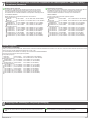
Mise en service d’un groupe des bornes de charge / Commissioning of a charging stations cluster
6
14/16 GEX5945401-01
(1) You need an APN name. For PAP, CHAP or PAP-CHAP authentication, a
username and password are required. This information are provided by your SIM
card supplier.
(2) You may need to update your network settings.
(3) You need an URL address, charging station identifier and (optional) password
provided by your charging station management system.
fr en Before starting configuration, it is recommended to switch off all charging stations
of the cluster.
There should not be other devices than EVlink Pro AC in the cluster.
Avant de commencer la configuration, il est recommandé d'éteindre toutes les
bornes de charge du groupe.
Il ne doit pas y avoir dans le groupe d'autres appareils que EVlink Pro AC.
(1) Vous avez besoin d’un nom APN. Pour l’authentification PAP, CHAP ou
PAP-CHAP, un nom d'utilisateur et un mot de passe sont nécessaires.
Ces informations sont fournies par votre fournisseur de la carte SIM.
(2) Vous pouvez avoir besoin de mettre à jour les paramètres de votre réseau.
(3) Vous avez besoin d’une adresse URL, l'identifiant de la borne de charge et le
mot de passe (facultatif) sont fournis par l’administrateur système de votre
borne de charge.
Mettez sous tension la borne de charge suivante du groupe sans modem embarqué.
Connectez la borne de charge avec eSetup.
Vérifiez que DHCP est allumé.
Configurez la supervision (3).
Redémarrez la borne de charge.
Répétez les opérations 7, 8, 9, 10 et 11 sur les autres bornes de charge restantes
du groupe.
Vérifiez la configuration du groupe avec eSetup pour la borne de charge avec
modem embarqué.
7
8
9
10
11
12
13
Power on the next charging station of the cluster without embedded modem.
Connect this charging station with eSetup.
Check that DHCP is ON.
Configure the supervision (3).
Restart the charging station.
Repeat operations 7, 8, 9, 10 and 11 on remaining charging stations of the cluster
.
Check the cluster configuration with eSetup from the charging station with
embedded modem.
7
8
9
10
11
12
13
Mettez sous tension uniquement la borne de charge avec le modem
embarqué.
Connectez la borne de charge avec eSetup.
Démarrez la configuration de connectivité en activant le modem embarqué (1).
Éteignez DHCP et activez le serveur DHCP (2), ne pas redémarrer la borne de
charge à ce stade.
Configurez la supervision (3).
Redémarrez la borne de charge.
1
2
3
4
5
6
Power on the charging station with embedded modem only.
Connect this charging station with eSetup.
Start connectivity configuration by activating the embedded modem (1).
Set DHCP OFF and activate DHCP server (2), don’t restart the charging station
at this stage.
Configure the supervision (3).
Restart the charging station.
1
3
4
5
6
2
711
...
p p p
modem 4G
eSetup
eSetup
12
12
13
p p p
y 10
modem 4G
16
...
eSetup

United Kingdom
UK Declaration of Conformity
Hereby, Schneider Electric Industries SAS, declares that the modems EVA1MS and EVA1MM used in EVlink Pro AC offer are in
compliance with the essential requirements and other
relevant provisions of Radio Equipment Regulations SI 2017 No. 1206.
The UK
EV22090601-UK
declaration of conformity can be downloaded on www.se.com/docs.
Frequency bands in which the radio equipment operates:
p
2G operating frequency:
p GSM 900 (Tx 880-915MHz max 33.15dBm EIRP, Rx 925-960MHz)
p GSM 1800 (Tx 1710-1785MHz max 29.54dBm EIRP, Rx 1805-1880MHz)
p
3G operating frequency:
p WCDMA Band I (Tx 1920-1980MHz max 23.35dBm, Rx 2110-2170MHz)
p WCDMA Band III (Tx 1710-1785MHz max 23.35dBm, Rx 1805-1880MHz)
p WCDMA Band VIII (Tx 880-915MHz max 23.35dBm, Rx 925-960MHz)
p
4G operating frequency:
p LTE FDD Band 1 (Tx 1920-1980MHz max 23.98dBm, Rx 2110-2170MHz)
p LTE FDD Band 3 (Tx 1710-1785MHz max 23.98dBm, Rx 1805-1880MHz)
p LTE FDD Band 7 (Tx 2500-2570MHz max 23.98dBm, Rx 2620-2690MHz)
p LTE FDD Band 8 (Tx 880-915MHz max 23.98dBm, Rx 925-960MHz)
p LTE FDD Band 20 (Tx 832-862MHz max 23.98dBm, Rx 791-821MHz)
p LTE FDD Band 28A (Tx 703-733MHz max 23.98dBm, Rx 758-788MHz)
p LTE TDD Band 38 (Tx 2570-2620MHz max 23.98dBm, Rx 2570-2620MHz)
p LTE TDD Band 40 (Tx 2300-2400MHz max 23.98dBm, Rx 2300-2400MHz)
7Déclarations de conformité concernant l'exposition aux radiofréquences / Radio Frequency
Compliance Statements
Déclaration UE de conformité
Par la présente, Schneider Electric Industries SAS, déclare que les modems
EVA1MS et EVA1MM utilisés dans l’offre EVlink Pro AC sont conformes aux
normes principales et aux autres dispositions de la directive RE 2014/53/UE.
La déclaration UE de conformité EV22090601 est disponible en téléchargement sur
le site www.se.com/docs.
Bandes de fréquence sur lesquelles l'équipement radio fonctionne :
p 2G operating frequency:
p GSM 900 (Tx 880-915MHz max 33.15dBm EIRP, Rx 925-960MHz)
p GSM 1800 (Tx 1710-1785MHz max 29.54dBm EIRP, Rx 1805-1880MHz)
p 3G operating frequency:
p
WCDMA Band I (Tx 1920-1980MHz max 23.35dBm, Rx 2110-2170MHz)
p
WCDMA Band III (Tx 1710-1785MHz max 23.35dBm, Rx 1805-1880MHz)
p
WCDMA Band VIII (Tx 880-915MHz max 23.35dBm, Rx 925-960MHz)
p 4G operating frequency:
p
LTE FDD Band 1 (Tx 1920-1980MHz max 23.98dBm, Rx 2110-2170MHz)
p
LTE FDD Band 3 (Tx 1710-1785MHz max 23.98dBm, Rx 1805-1880MHz)
p
LTE FDD Band 7 (Tx 2500-2570MHz max 23.98dBm, Rx 2620-2690MHz)
p
LTE FDD Band 8 (Tx 880-915MHz max 23.98dBm, Rx 925-960MHz)
p
LTE FDD Band 20 (Tx 832-862MHz max 23.98dBm, Rx 791-821MHz)
p
LTE FDD Band 28A (Tx 703-733MHz max 23.98dBm, Rx 758-788MHz)
p
LTE TDD Band 38 (Tx 2570-2620MHz max 23.98dBm, Rx 2570-2620MHz)
p
LTE TDD Band 40 (Tx 2300-2400MHz max 23.98dBm, Rx 2300-2400MHz)
fr EU Declaration of Conformity
Hereby, Schneider Electric Industries SAS, declares that the modems EVA1MS and
EVA1MM used in EVlink Pro AC offer are in
compliance with the essential
requirements and other
relevant provisions of RE Directive 2014/53/EU.
The EU EV22090601 declaration of conformity can be downloaded on
www.se.com/docs.
Frequency bands in which the radio equipment operates:
p
2G operating frequency:
p GSM 900 (Tx 880-915MHz max 33.15dBm EIRP, Rx 925-960MHz)
p GSM 1800 (Tx 1710-1785MHz max 29.54dBm EIRP, Rx 1805-1880MHz)
p
3G operating frequency:
p WCDMA Band I (Tx 1920-1980MHz max 23.35dBm, Rx 2110-2170MHz)
p WCDMA Band III (Tx 1710-1785MHz max 23.35dBm, Rx 1805-1880MHz)
p WCDMA Band VIII (Tx 880-915MHz max 23.35dBm, Rx 925-960MHz)
p
4G operating frequency:
p LTE FDD Band 1 (Tx 1920-1980MHz max 23.98dBm, Rx 2110-2170MHz)
p LTE FDD Band 3 (Tx 1710-1785MHz max 23.98dBm, Rx 1805-1880MHz)
p LTE FDD Band 7 (Tx 2500-2570MHz max 23.98dBm, Rx 2620-2690MHz)
p LTE FDD Band 8 (Tx 880-915MHz max 23.98dBm, Rx 925-960MHz)
p LTE FDD Band 20 (Tx 832-862MHz max 23.98dBm, Rx 791-821MHz)
p LTE FDD Band 28A (Tx 703-733MHz max 23.98dBm, Rx 758-788MHz)
p LTE TDD Band 38 (Tx 2570-2620MHz max 23.98dBm, Rx 2570-2620MHz)
p LTE TDD Band 40 (Tx 2300-2400MHz max 23.98dBm, Rx 2300-2400MHz)
en
8Recyclage des emballages / Recycling Packaging
Les matériaux d’emballage de cet appareil sont recyclables. Contribuez à la
protection de l’environnement en les déposant dans les conteneurs prévus à cet
effet.
fr The packaging materials from this equipment can be recycled. Please help protect
the environment by recycling them in appropriate containers.
en
15/16GEX5945401-01

© 2023 Schneider Electric - All rights reserved.
Schneider Electric Limited
Stafford Park 5
Telford, TF3 3BL
United Kingdom
www.se.com/uk
Schneider Electric Industries SAS
35, rue Joseph Monier
CS 30323
F - 92506 Rueil Malmaison Cedex
www.se.com
The Bluetooth® word mark and logos are registered trademarks owned by Bluetooth SIG, Inc. and any use of such marks by Schneider Electric is under
license. Other trademarks and trade names are those of their respective owners.
GEX5945401-01 16/16
-
 1
1
-
 2
2
-
 3
3
-
 4
4
-
 5
5
-
 6
6
-
 7
7
-
 8
8
-
 9
9
-
 10
10
-
 11
11
-
 12
12
-
 13
13
-
 14
14
-
 15
15
-
 16
16


Schneider Electric EVlink Pro AC Instruction Sheet
- Taper
- Instruction Sheet
dans d''autres langues
- English: Schneider Electric EVlink Pro AC
Documents connexes
-
Schneider Electric EVP3MM 4G Cellular Modem Mode d'emploi
-
Schneider Electric EVlink Pro AC Instruction Sheet
-
-
-
-
Schneider Electric PowerPacT B I-Line Circuit Breakers Instruction Sheet
-