Zanussi ZHP 613 Manuel utilisateur
- Catégorie
- Hottes
- Taper
- Manuel utilisateur

Cappa
Cooker hood
Hotte de cuisine
Dunstabzugshaube
Dampkap
ZHP 637 - ZHP 631 –
ZHP613
ZHP 615 - ZHP 625
MANUALE DI INSTALLAZIONE, USO E MANUTENZIONE
INSTALLATION, USE AND MAINTENANCE HANDBOOK
MANUEL D’INSTRUCTIONS POUR L’INSTALLATION, L’EMPLOI ET L’ENTRETIEN
HANDBUCH FÜR INSTALLATION, BEDIENUNG UND WARTUNG
INSTRUCTIES VOOR MONTAGE, GEBRUIK EN ONDERHOUD

2
2
INDICE
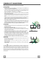
CONSIGLI E SUGGERIMENTI..............................................................................................................................................3
CARATTERISTICHE..............................................................................................................................................................4
INSTALLAZIONE....................................................................................................................................................................5
USO ........................................................................................................................................................................................7
MANUTENZIONE...................................................................................................................................................................8
INDEX
RECOMMENDATIONS AND SUGGESTIONS....................................................................................................................10
CHARACTERISTICS............................................................................................................................................................11
INSTALLATION....................................................................................................................................................................12
USE.......................................................................................................................................................................................14
MAINTENANCE....................................................................................................................................................................15
SOMMAIRE
CONSEILS ET SUGGESTIONS ..........................................................................................................................................17
CARACTERISTIQUES.........................................................................................................................................................18
INSTALLATION....................................................................................................................................................................19
UTILISATION........................................................................................................................................................................21
ENTRETIEN..........................................................................................................................................................................22
INHALTSVERZEICHNIS
EMPFEHLUNGEN UND HINWEISE....................................................................................................................................24
CHARAKTERISTIKEN..........................................................................................................................................................25
MONTAGE............................................................................................................................................................................26
BEDIENUNG.........................................................................................................................................................................28
WARTUNG............................................................................................................................................................................29
INHOUDSOPGAVE
ADVIEZEN EN SUGGESTIES.............................................................................................................................................31
EIGENSCHAPPEN...............................................................................................................................................................32
INSTALLATIE.......................................................................................................................................................................33
GEBRUIK..............................................................................................................................................................................35
ONDERHOUD ......................................................................................................................................................................36
IT
EN
FR
DE
NL

IT
3
3
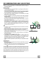
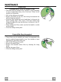
CONSIGLI E SUGGERIMENTI
Questo libretto d
i istruzioni per l'uso è previsto per più versioni dell' appare
c
chio.
É possibile che siano descritti singoli particolari della dotazione, che non riguar-
dano il Vostro apparecchio.
INSTALLAZIONE
• Il produttore declina qualsiasi responsabilità per danni dovuti ad installazione non
corretta o non conforme alle regole dell’arte.
• La distanza minima di sicurezza tra il Piano di cottura e la Cappa deve essere di
650 mm, (alcuni modelli possono essere installati ad un’altezza inferiore, fare rife-
rimento ai paragrafi ingombro e installazione).
• Verificare che la tensione di rete corrisponda a quella riportata nella targhetta
posta all’interno della Cappa.
• Per Apparecchi in Classe I
a
accertarsi che l’impianto elettrico domestico garanti-
sca un corretto scarico a terra.
• Collegare la Cappa all’uscita dell’aria aspirata con tubazione di diametro pari o
superiore a 120 mm. Il percorso della tubazione deve essere il più breve possibi-
le.
• Non collegare la Cappa a condotti di scarico dei fumi prodotti da combustione
(caldaie, caminetti, ecc.).
• Nel caso in cui nella stanza vengano utilizzati sia la Cappa che apparecchi non
azionati da energia elettrica (ad esempio apparecchi utilizzatori di gas), si deve
provvedere ad una aerazione sufficiente dell’ambiente. Se la cucina ne fosse
sprovvista, praticare un’apertura che comunichi con l’esterno, per garantire il ri-
chiamo d’aria pulita.
USO
• La Cappa è stata progettata esclusivamente per uso domestico, per abbattere gli
odori della cucina.
• Non fare mai uso improprio della Cappa.
• Non lasciare fiamme libere a forte intensità sotto la Cappa in funzione.
• Regolare sempre le fiamme in modo da evitare una evidente fuoriuscita laterale
delle stesse rispetto al fondo delle pentole.
• Controllare le friggitrici durante l’uso: l’olio surriscaldato potrebbe infiammarsi.
• Non preparare alimenti flambè sotto la cappa da cucina; pericolo d'incendio.
• Questo apparecchio non deve essere utilizzato da persone (bambini inclusi) con
ridotte capacità psichiche, sensoriali o mentali, oppure da persone senza espe-
rienza e conoscenza, a meno che non siano controllati o istruiti all’uso
dell’apparecchio da persone responsabili della loro sicurezza.
• I bambini devono essere supervisionati per assicurarsi che non giochino con
l’apparecchio.
MANUTENZIONE
• Prima di procedere a qualsiasi operazione di manutenzione, disinserire la Cappa
togliendo la spina elettrica o spegnendo l’interruttore generale.
• Effettuare una scrupolosa e tempestiva manutenzione dei Filtri secondo gli inter-
valli consigliati (Rischio di incendio).
• Per la pulizia delle superfici della Cappa è sufficiente utilizzare un panno umido e
detersivo liquido neutro.
Il simbolo sul prodotto o sulla confezione indica che il prodotto non deve essere considerato
come un normale rifiuto domestico, ma deve essere portato nel punto di raccolta appropriato per
il riciclaggio di apparecchiature elettriche ed elettroniche. Provvedendo a smaltire questo prodot-
to in modo appropriato, si contribuisce a evitare potenziali conseguenze negative per l’ambiente
e per la salute, che potrebbero derivare da uno smaltimento inadeguato del prodotto. Per infor-
mazioni più dettagliate sul riciclaggio di questo prodotto, contattare l’ufficio comunale, il servizio
locale di smaltimento rifiuti o il negozio in cui è stato acquistato il prodotto.

IT
4
4
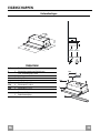
CARATTERISTICHE
Ingombro
0÷152
280
598 - 898
175
ø 120
Min.
500mm
Min.
650mm
Componenti
Rif. Q.tà Componenti di Prodotto
1 1 Corpo Cappa completo di: Comandi, Luce, Gruppo
Ventilatore, Filtri
8 1 Griglia direzionata Uscita Aria
20 1 Profilo chiusura
Rif. Q.tà Componenti di Installazione
12a 4 Viti 4,2 x 44,4
12e 2 Viti 2,9 x 9,5
Q.tà Documentazione
1 Libretto Istruzioni
12e
8
1
12a
20

IT
5
5
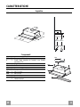
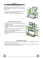
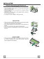
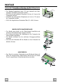
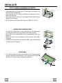
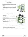
INSTALLAZIONE
Foratura Piano di supporto e Montaggio Cappa
MONTAGGIO CON VITI
• Il Piano di supporto della Cappa deve essere rientrante di 135
mm dal Piano inferiore dei Pensili.
• Forare ø 4,5 mm il supporto utilizzando la Dima di foratura in
dotazione.
• Praticare un foro ø 125 mm sul Piano di supporto, utilizzando
la Dima di foratura in dotazione.
• Fissare con 4 Viti 12a (4,2 x 44,4) in dotazione.
12a
135
125125
MONTAGGIO CON FISSAGGIO A SCATTO
• La Cappa può essere installata direttamente sul piano inferiore
dei Pensili con i Supporti laterali a scatto.
• Praticare un incasso sul piano inferiore del Pensile, come indi-
cato.
• Inserire la Cappa fino ad agganciare i Supporti laterali a scatto.
• Bloccare definitivamente serrando le Viti Vf dal sotto della
Cappa.
15
264
502 - 802
Vf
PROFILO DI CHIUSURA
• Lo spazio tra il bordo della Cappa e la Parete di fondo può es-
sere chiuso applicando il Profilo 20 in dotazione con le Viti già
predisposte a questo scopo.
20

IT
6
6
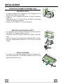
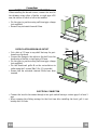
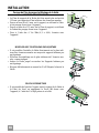
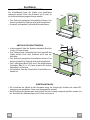
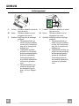
Connessioni
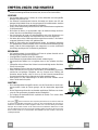
USCITA ARIA VERSIONE ASPIRANTE
Per installazione in Versione Aspirante collegare la
Cappa alla tubazione di uscita per mezzo di un tubo
rigido o flessibile di ø120 mm, la cui scelta è lasciata
all'installatore.
• Fissare il tubo con adeguate fascette stringitubo. Il
materiale occorrente non è in dotazione.
• Togliere eventuali Filtri Antiodore al Carbone attivo.
ø 120
USCITA ARIA VERSIONE FILTRANTE
• Praticare un foro ø 125 mm sull’eventuale Mensola
soprastante la Cappa.
• Collegare la Flangia al foro di uscita sulla Mensola
soprastante la Cappa con un tubo rigido o flessibile di
ø120 mm.
• Fissare il tubo con adeguate fascette stringitubo. Il
materiale occorrente non è in dotazione.
• Fissare la Griglia direzionata 8 sull’uscita con 2 Viti
12e (2,9 x 9,5) in dotazione.
• Assicurarsi della presenza dei Filtri antiodore al Car-
bone attivo.
8
9
125
8
9
125
12e
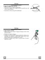
CONNESSIONE ELETTRICA
• Collegare la Cappa all’Alimentazione di Rete interponendo un Interruttore bipolare con a-
pertura dei contatti di almeno 3 mm.
• Dopo aver installato la cappa è necessario per la prima volta aprire il carrello scorrevole e-
nergicamente fino a sentire lo scatto di fine corsa.

IT
7
7
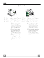
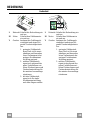
USO
Quadro comandi
L Luci Accende e spegne l’Impianto
di Illuminazione.
M Motore Accende e spegne il motore
Aspirazione.
V Velocità Determina la velocità di e-
sercizio:
1. Velocità minima, adatta
ad un ricambio d’aria
continuo particolarmente
silenzioso, in presenza di
pochi vapori di cottura.
2. Velocità media, adatta
alla maggior parte delle
condizioni d’uso, dato
l’ottimo rapporto tra por-
tata d’aria trattata e livel-
lo sonoro.
3. Velocità massima, adatta
a fronteggiare le massime
emissioni di vapore di
cottura, anche per tempi
prolungati.
L Luci Accende e spegne l’Impianto
di Illuminazione.
M Motore Accende e spegne il motore
Aspirazione.
V Velocità Determina la velocità di e-
sercizio:
1. Velocità minima, adatta
ad un ricambio d’aria
continuo particolarmente
silenzioso, in presenza di
pochi vapori di cottura.
2. Velocità media, adatta alla
maggior parte delle con-
dizioni d’uso, dato
l’ottimo rapporto tra por-
tata d’aria trattata e livello
sonoro.
L
M - V
0
1
0
1
2
3
L
M-V

IT
8
8
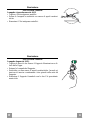
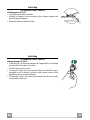
MANUTENZIONE
Filtri antigrasso
PULIZIA FILTRI ANTIGRASSO METALLICI AUTOPORTANTI
• Sono lavabili anche in lavastoviglie, e necessitano di essere
lavati ogni 2 mesi circa di utilizzo o più frequentemente, per un
uso particolarmente intenso.
• Estrarre il carrello aspirante.
• Togliere i Filtri uno alla volta, agendo sugli appositi agganci.
• Lavare i Filtri evitando di piegarli, e lasciarli asciugare prima
di rimontarli. (Un’eventuale cambiamento del colore della su-
perficie del filtro, che potrebbe verificarsi nel tempo, non pre-
giudica assolutamente l’efficienza dello stesso.)
• Rimontarli facendo attenzione a mantenere la maniglia verso la
parte visibile esterna.
• Chiudere il carrello aspirante.
Filtri antiodore (Versione Filtrante)
SOSTITUZIONE
• Non sono lavabili né rigenerabili, vanno sostituiti ogni 4 mesi
circa di utilizzo o più frequentemente, per un uso particolar-
mente intenso.
• Estrarre il carrello aspirante.
• Togliere i Filtri Antigrasso
• Rimuovere il Filtro antiodore al Carbone attivo saturo, agendo
sugli appositi agganci.
• Rimontare i Filtri antigrasso.
• Richiudere il carrello aspirante.

IT
9
9
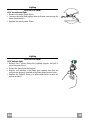
Illuminazione
SOSTITUZIONE LAMPADE
Lampade a incandescenza da 40 W
• Togliere i Filtri antigrasso metallici.
• Svitare le Lampade e sostituirle con nuove di uguali caratteri-
stiche.
• Rimontare i Filtri antigrasso metallici.
Illuminazione
SOSTITUZIONE LAMPADE
Lampade alogene da 20 W.
• Togliere le due viti che fissano il Supporto illuminazione e sfi-
larlo dalla Cappa.
• Estrarre la Lampada dal Supporto.
• Sostituirla con una nuova di uguali caratteristiche, facendo at-
tenzione di inserire correttamente i due spinotti nella sede del
Supporto.
• Rimontare il Supporto fissandola con le due Viti precedente-
mente tolte.

EN
1
0
10
RECOMMENDATIONS AND SUGGESTIONS
The Instructions for Use apply to several versions of this appliance. Accor
d-
ingly, you may find descriptions of individual features that do not apply to
your specific appliance.
INSTALLATION
• The manufacturer will not be held liable for any damages resulting from in-
correct or improper installation.
• The minimum safety distance between the cooker top and the extractor
hood is 650 mm (some models can be installed at a lower height, please re-
fer to the paragraphs on working dimensions and installation).
• Check that the mains voltage corresponds to that indicated on the rating
plate fixed to the inside of the hood.
• For Class I appliances, check that the domestic power supply guarantees
adequate earthing.
Connect the extractor to the exhaust flue through a pipe of minimum diame-
ter 120 mm. The route of the flue must be as short as possible.
• Do not connect the extractor hood to exhaust ducts carrying combustion
fumes (boilers, fireplaces, etc.).
• If the extractor is used in conjunction with non-electrical appliances (e.g. gas
burning appliances), a sufficient degree of aeration must be guaranteed in
the room in order to prevent the backflow of exhaust gas. The kitchen must
have an opening communicating directly with the open air in order to
guarantee the entry of clean air.
USE
• The extractor hood has been designed exclusively for domestic use to elimi-
nate kitchen smells.
• Never use the hood for purposes other than for which it has been designed.
• Never leave high naked flames under the hood when it is in operation.
• Adjust the flame intensity to direct it onto the bottom of the pan only, making
sure that it does not engulf the sides.
• Deep fat fryers must be continuously monitored during use: overheated oil
can burst into flames.
• Do not flambè under the range hood; risk of fire
• This appliance is not intended for use by persons (including children) with
reduced physical, sensory or mental capabilities, or lack of experience and
knowledge, unless they have been given supervision or instruction concern-
ing use of the appliance by a person responsible for their safety.
• Children should be supervised to ensure that they do not play with the appli-
ance.
MAINTENANCE
• Switch off or unplug the appliance from the mains supply before carrying out
any maintenance work.
• Clean and/or replace the Filters after the specified time period (Fire hazard).
• Clean the hood using a damp cloth and a neutral liquid detergent.
The symbol on the product or on its packaging indicates that this product may not be treated
as household waste. Instead it shall be handed over to the applicable collection point for the
recycling of electrical and electronic equipment. By ensuring this product is disposed of correctly,
you will help prevent potential negative consequences for the environment and human health,
which could otherwise be caused by inappropriate waste handling of this product. For more
detailed information about recycling of this product, please contact your local city office, your
household waste disposal service or the shop where you purchased the product.

EN
1
1
11
CHARACTERISTICS
Dimensions
0÷152
280
598 - 898
175
ø 120
Min.
500mm
Min.
650mm
Components
Ref. Q.ty Product Components
1 1 Hood Body, complete with: Controls, Light, Blower,
Filters
8 1 Directional Air Outlet grille
20 1 Closing element
Ref. Q.ty Installation Components
12a 4 Screws 4,2 x 44,4
12e 2 Screws 2,9 x 9,5
Q.ty Documentation
1 Instruction Manual
12e
8
1
12a
20

EN
1
2
12
INSTALLATION
Drilling the Support surface and Fitting the Hood
SCREW FITTING
• The hood support surface must be 135 mm above the bottom
surface of the wall units.
• Drill the support with a ø 4,5 mm drill bit, using the drilling
template provided.
• Cut a hole ø 125 mm in size on the support surface, using the
drilling template provided.
• Fix using the 4 screws 12a (4,2 x 44,4) provided.
12a
135
125125
SNAP-ON FITTING
• The hood can be installed either directly on the bottom surface
of the wall units using snap-on side supports.
• Cut a fitted opening in the bottom surface of the wall unit, as
shown.
• Insert the hood until the side supports snap into place.
• Lock in position by tightening the screws Vf from underneath
the hood.
15
264
502 - 802
Vf
CLOSING ELEMENT
• The space between the edge of the hood and the rear wall can
be closed by applying the element 20 provided, using the
screws supplied for this purpose.
20

EN
1
3
13
Connections
DUCTED VERSION AIR EXHAUST SYSTEM
When installing the ducted version, connect the hood to
the chimney using either a flexible or rigid pipe ø120
mm, the choice of which is left to the installer.
• Fix the pipe in position using sufficient pipe clamps
(not supplied).
• Remove any activated charcoal filters.
ø 120
RECIRCULATION VERSION AIR OUTLET
• Cut a hole ø 125 mm in any shelf that may be posi-
tioned over the hood.
• Connect the flange to the outlet on the shelf over the
hood using a flexible or rigid pipe ø120 mm.
• Fix the pipe in position using sufficient pipe clamps
(not supplied).
• Fix the directional grille 8 on the recirculation air
outlet using the 2 screws 12e (2,9 x 9,5) provided.
• Ensure that the activated charcoal filters have been
inserted.
8
9
125
8
9
125
12e
ELECTRICAL CONNECTION
• Connect the hood to the mains through a two-pole switch having a contact gap of at least 3
mm.
• When opening the sliding carriage for the first time after installing the hood, pull it out
briskly until it clicks.

EN
1
4
14
USE
Control panel
L Light Switches the lighting system
on and off.
M Motor Switches the extractor motor
on and off.
V Speed Sets the operating speed of
the extractor:
1. Low speed, used for a
continuous and silent air
change in the presence of
light cooking vapour.
2. Medium speed, suitable
for most operating condi-
tions given the optimum
treated air flow/noise
level ratio.
3. Maximum speed, used for
eliminating the highest
cooking vapour emission,
including long periods.
L Light Switches the lighting system
on and off.
M Motor Switches the extractor motor
on and off.
V Speed Sets the operating speed of
the extractor:
1. Low speed, used for a
continuous and silent air
change in the presence of
light cooking vapour.
2. Medium speed, suitable
for most operating condi-
tions given the optimum
treated air flow/noise
level ratio.
L
M - V
0
1
0
1
2
3
L
M-V

EN
1
5
15
MAINTENANCE
Grease filters
CLEANING METAL CASSETTE GREASE FILTERS
• The filters must be cleaned every 2 months, or more frequently
in case of particularly heavy use of the hood. Filters can be
washed in a dishwasher.
• Pull out the sliding suction panel.
• Remove the filters one by one, after having disconnected the
relative fastening elements.
• Wash the filters, taking care not to bend them. Let them get dry
before refitting them. (The colour of the filter surface may
change throughout the time but this has no influence to the fil-
ter efficiency).
• When refitting the filters, make sure that the handle is visible
on the outside.
• Close the sliding suction panel.
Charcoal filter (Recycling version)
REPLACING CHARCOAL FILTERS
• These filters are not washable and cannot be regenerated, and
must be replaced approximately every four months or more
frequently by particularly heavy use.
• Pull out the sliding suction panel.
• Remove the grease filters.
• Remove the saturated carbon filter by releasing the fixing
hooks
• Replace the grease filters.
• Close the sliding suction panel.

EN
1
6
16
Lighting
LIGHT REPLACEMENT
40 W incandescent light.
• Remove the metal grease filters.
• Unscrew the bulbs and replace them with new ones having the
same characteristics.
• Replace the metal grease filters.
Lighting
LIGHT REPLACEMENT
20 W halogen light.
• Remove the 2 screws fixing the Lighting support, and pull it
out of from the Hood.
• Extract the lamp from the Support.
• Replace with another of the same type, making sure that the
two pins are properly inserted in the lamp holder socket holes.
• Replace the Support, fixing it in place with the two screws re-
moved as above.

FR
1
7
17
CONSEILS ET SUGGESTIONS
La présente notice d'emploi vaut pour plusieurs versions de l'appareil. Elle peut conte-
nir des descriptions d'accessoires ne figurant pas dans votre appareil.
INSTALLATION
• Le fabricant décline toute responsabilité en cas de dommage dû à une installation non
correcte ou non conforme aux règles de l’art.
• La distance minimale de sécurité entre le plan de cuisson et la hotte doit être de 650
mm au moins (certains modèles peuvent être installés à une hauteur inférieure : se re-
porter aux paragraphes « Encombrement » et « Installation »).
• Vérifier que la tension du secteur correspond à la valeur qui figure sur la plaquette
apposée à l’intérieur de la hotte.
• Pour les Appareils appartenant à la Ière Classe, veiller à ce que la mise à la terre de
l’installation électrique domestique ait été effectuée conformément aux normes en vi-
gueur.
• Connecter la hotte à la sortie d’air aspiré à l’aide d’une tuyauterie d’un diamètre égal ou
supérieur à 120 mm. Le parcours de la tuyauterie doit être le plus court possible.
• Ne pas connecter la hotte à des conduites d’évacuation de fumées issues d’une com-
bustion tel que (Chaudière, cheminée, etc…).
• Si vous utilisez des appareils qui ne fonctionnent pas à l’électricité dans la pièce ou est
installée la hotte (par exemple: des appareils fonctionnant au gaz), vous devez prévoir
une aération suffisante du milieu. Si la cuisine en est dépourvue, pratiquez une ouver-
ture qui communique avec l’extérieur pour garantir l’infiltration de l’air pur.
UTILISATION
• La hotte a été conçue exclusivement pour l’usage domestique, dans le but d’éliminer
les odeurs de la cuisine.
• Ne jamais utiliser abusivement la hotte.
• Ne pas laisser les flammes libres à forte intensité quand la hotte est en service.
• Toujours régler les flammes de manière à éviter toute sortie latérale de ces dernières
par rapport au fond des marmites.
• Contrôler les friteuses lors de l’utilisation car l’huile surchauffée pourrait s’enflammer.
• Ne pas préparer d’aliments flambés sous la hotte de cuisine : risque d’incendie
• Cet appareil ne doit pas être utilisé par des personnes (y compris les enfants) ayant
des capacités psychiques, sensorielles ou mentales réduites, ni par des personnes
n’ayant pas l’expérience et la connaissance de ce type d’appareils, à moins d'être sous
le contrôle et la formation de personnes responsables de leur sécurité.
• Les enfants doivent être surveillés pour s'assurer qu'ils ne jouent pas avec l'appareil.
ENTRETIEN
• Avant de procéder à toute opération d’entretien, retirer la hotte en retirant la fiche ou en
actionnant l’interrupteur général.
• Effectuer un entretien scrupuleux et en temps dû des Filtres, à la cadence conseillée
(Risque d’incendie).
• Pour le nettoyage des surfaces de la hotte, il suffit d’utiliser un chiffon humide et déter-
sif liquide neutre.
Le symbole sur le produit ou son emballage indique que ce produit ne peut être traité comme
déchet ménager. Il doit plutôt être remis au point de ramassage concerné, se chargeant du recy-
clage du matériel électrique et électronique. En vous assurant que ce produit est éliminé correc-
tement, vous favorisez la prévention des conséquences négatives pour l’environnement et la santé
humaine qui, sinon, seraient le résultat d’un traitement inapproprié des déchets de ce produit. Pour
obtenir plus de détails sur le recyclage de ce produit, veuillez prendre contact avec le bureau muni-
cipal de votre région, votre service d’élimination des déchets ménagers ou le magasin où vous avez
acheté le produit.

FR
1
8
18
CARACTERISTIQUES
Encombrement
0÷152
280
598 - 898
175
ø 120
Min.
500mm
Min.
650mm
Composants
Réf. Q.té Composants de Produit
1 1 Corps Hotte équipé de:Commandes, Lumière, Groupe
Ventilateur, Filtres
8 1 Grille orientée Sortie de l ’Air
20 1 Profil fermeture
Réf. Q.té Composants pour l ’installation
12a 4 Vis 4,2 x 44,4
12e 2 Vis 2,9 x 9,5
Q.té Documentation
1 Manuel d’instructions
12e
8
1
12a
20

FR
1
9
19
INSTALLATION
Perçage du Plan de support et Montage de la Hotte
MONTAGE AU MOYEN DE VIS
• Le Plan de support de la Hotte doit être monté plus en haut de
135 mm. par rapport au Plan inférieur des Armoires murales.
• Percer un trou de ø 4,5 mm. sur le support, en utilisant le Gaba-
rit de perçage fourni avec l’appareil.
• Percer un trou de ø 125 mm. sur le Plan de support, en utilisant
le Gabarit de perçage fourni avec l’appareil.
• Fixer à l’aide des 4 Vis 12a (4,2 x 44,4) fournies avec
l’appareil.
12a
135
125125
MONTAGE AVEC FIXATION PAR ENCLIQUETAGE
• Il est possible d’installer la Hotte directement sur le plan infé-
rieur des Armoires murales au moyen de supports latéraux par
encliquetage.
• Effectuer un emboîtage sur le plan inférieur de l’Armoire mu-
rale, comme indiqué.
• Insérer la Hotte jusqu’à accrocher les Supports latéraux par
encliquetage.
• Bloquer définitivement en serrant les Vis Vf depuis le bas de la
Hotte.
15
264
502 - 802
Vf
PROFIL DE FERMETURE
• Il est possible de boucher l’espace entre le rebord de la Hotte et
la Paroi du fond, en appliquant le Profil 20 fourni avec
l’appareil, à l’aide des Vis déjà prévus à cet effet.
20

FR
2
0
20
Branchements
SORTIE AIR VERSION EVACUATION
En cas d’installation en version évacuation, brancher la
hotte à la tuyauterie de sortie via un tube rigide ou
flexible de ø 120 mm, au choix de l’installateur.
• Fixer le tube par des colliers appropriés. Le matériau
nécessaire n’est pas fourni.
• Retirer les éventuels filtres anti-odeur au charbon
actif.
ø 120
SORTIE AIR VERSION RECYCLAGE
• Percer un trou de ø 125 mm. sur l’éventuelle Tablette
qui se trouve au-dessus de la Hotte.
• Connecter la Flasque au trou de sortie sur la Tablette
qui se trouve au-dessus de la Hotte, au moyen d’un
tuyau rigide ou flexible de ø120 mm.
• Fixer le tube par des colliers appropriés. Le matériau
nécessaire n’est pas fourni.
• Fixer la Grille orientée 8 sur la sortie de l’air recyclé
à l’aide de 2 Vis 12e (2,9 x 9,5) fournies avec
l’appareil.
• S’assurer de la présence des filtres anti-odeur au
charbon actif.
8
9
125
8
9
125
12e
BRANCHEMENT ELECTRIQUE
• Brancher la hotte sur le secteur en interposant un interrupteur bipolaire avec ouverture des
contacts d’au moins 3 mm.
• Après avoir installé la hotte, il est indispensable pour la première fois d’ouvrir le chariot
coulissant de façon énergique, jusqu’à ce que l’on entende le déclic de fin de course.
La page est en cours de chargement...
La page est en cours de chargement...
La page est en cours de chargement...
La page est en cours de chargement...
La page est en cours de chargement...
La page est en cours de chargement...
La page est en cours de chargement...
La page est en cours de chargement...
La page est en cours de chargement...
La page est en cours de chargement...
La page est en cours de chargement...
La page est en cours de chargement...
La page est en cours de chargement...
La page est en cours de chargement...
La page est en cours de chargement...
La page est en cours de chargement...
La page est en cours de chargement...
La page est en cours de chargement...
La page est en cours de chargement...
La page est en cours de chargement...
-
 1
1
-
 2
2
-
 3
3
-
 4
4
-
 5
5
-
 6
6
-
 7
7
-
 8
8
-
 9
9
-
 10
10
-
 11
11
-
 12
12
-
 13
13
-
 14
14
-
 15
15
-
 16
16
-
 17
17
-
 18
18
-
 19
19
-
 20
20
-
 21
21
-
 22
22
-
 23
23
-
 24
24
-
 25
25
-
 26
26
-
 27
27
-
 28
28
-
 29
29
-
 30
30
-
 31
31
-
 32
32
-
 33
33
-
 34
34
-
 35
35
-
 36
36
-
 37
37
-
 38
38
-
 39
39
-
 40
40


Zanussi ZHP 613 Manuel utilisateur
- Catégorie
- Hottes
- Taper
- Manuel utilisateur
dans d''autres langues
- italiano: Zanussi ZHP 613 Manuale utente
- English: Zanussi ZHP 613 User manual
- Deutsch: Zanussi ZHP 613 Benutzerhandbuch
- Nederlands: Zanussi ZHP 613 Handleiding
Documents connexes
Autres documents
-
Progress PDP6010E Manuel utilisateur
-
ZANKER ZKP6010X Manuel utilisateur
-
Beko CTB 6407 Le manuel du propriétaire
-
Brandt AT249XE1 Le manuel du propriétaire
-
De Dietrich DHT386XP1 Le manuel du propriétaire
-
Franke FGC606XS Le manuel du propriétaire
-
Electrolux EFC9423X Manuel utilisateur
-
-
De Dietrich DHT6605X Le manuel du propriétaire
-