Maytag MED5630HW Le manuel du propriétaire
- Catégorie
- Sèche-linge électriques
- Taper
- Le manuel du propriétaire

ELECTRIC DRYER OWNER’S MANUAL
GUIDE D’UTILISATION DE LA SÉCHEUSE ÉLECTRIQUE
Table of Contents
Dryer Safety
...........................................................2
Dryer Safety
.......................................................2
Dryer Maintenance and Care
..................................5
Cleaning the Dryer Location
................................5
Cleaning the Dryer Interior
..................................5
Removing Accumulated Lint
................................5
Cleaning the Lint Screen.....................................5
Changing the Drum Light (on some models) .........6
Check Your Vent System for Good Airflow
............6
Maintain Good Airflow
.........................................6
Nonuse, Storage, and Moving Care
.....................6
Special Instructions for Steam Models
.................7
Installation Instructions
..........................................7
Requirements................................................... ......7
Tools and Parts
..................................................7
Location Requirements.......................................8
Electrical Requirements – U.S.A..........................9
Electric Requirements – Canada ....................... 10
Installation
........................................................... 11
Install Leveling Legs
......................................... 11
Electrical Installation – U.S.A.
............................ 11
Venting Requirements
...................................... 17
Plan Vent System
............................................. 17
Install Vent System........................................... 19
Connect Inlet Hoses ......................................... 19
Connect Vent (Vented Models Only)
.................. 20
Level Dryer ...................................................... 21
Complete Installation Checklist.... ...................... 21
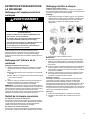
Sécurité de la sécheuse ....................................... 22
Sécurité de la sécheuse
.................................... 22
Entretien et réparation de la sécheuse ................. 25
Nettoyage de l’emplacement de la
sécheuse
......................................................... 25
Nettoyage de l’intérieur de la sécheuse.............. 25
Retrait de la charpie accumulée ........................ 25
Nettoyage du filtre à charpie.............................. 25
Changement de l’ampoule d’éclairage du
tambour (sur certains modèles)
......................... 26
Vérification d’une circulation d’air adéquate
pour le système d’évacuation
............................ 26
Pour maintenir une bonne circulation d’air .......... 26
Précautions à prendre lorsque l’appareil
n’est pas utilisé, est entreposé ou
déménagé
....................................................... 27
Instructions spécifiques pour les modèles
vapeur
............................................................. 27
Instructions d’installation
..................................... 28
Spécifications
...................................................... 28
Outils et pièces ................................................ 28
Exigences d’emplacement ................................ 29
Spécifications électriques – É.-U. ...................... 30
Spécifications électriques – Canada .................. 31
L’installation
......................................................... 32
Installation des pieds de nivellement.................. 32
Installation Électrique - U.S.A............................ 32
Exigences concernant l'évacuation
.................... 38
Planification des circuits de conduits
.................. 39
Installation du conduit d’évacuation
................... 41
Raccordement des tuyaux d’alimentation
........... 41
Raccorder le conduit d’évacuation (sur les
modèles avec conduit seulement)
...................... 42
Réglage de l’aplomb de la sécheuse.................. 43
Liste de vérification pour installation
terminée
.......................................................... 43
W11364660A
W11364661A-SP
Table des matières

2
DRYER SAFETY
Your safety and the safety of others are very important.
We have provided many important safety messages in this manual and on your appliance. Always read and obey all safety
messages.
This is the safety alert symbol.
This symbol alerts you to potential hazards that can kill or hurt you and others.
All safety messages will follow the safety alert symbol and either the word “DANGER” or “WARNING.” These
words mean:
DANGER
You can be killed or seriously injured if you don't
immediately follow instructions.
WARNING
You can be killed or seriously injured if you don’t follow
instructions.
All safety messages will tell you what the potential hazard is, tell you how to reduce the chance of injury, and tell you what can
happen if the instructions are not followed.
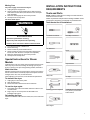
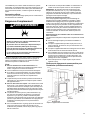
WARNING — “Risk of Fire”
− Clothes dryer installation must be performed by a qualified installer.
− Install the clothes dryer according to the manufacturer's instructions and local codes.
− Do not install a clothes dryer with flexible plastic venting materials or flexible metal (foil
type) duct. If flexible metal duct is installed, it must be of a specific type identified by the
appliance manufacturer as suitable for use with clothes dryers. Flexible venting materials
are known to collapse, be easily crushed, and trap lint. These conditions will obstruct
clothes dryer airflow and increase the risk of fire.
− To reduce the risk of severe injury or death, follow all installation instructions.
− Save these instructions.

3
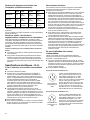
IMPORTANT SAFETY INSTRUCTIONS
WARNING: To reduce the risk of fire, electric shock, or injury to persons when using your appliance, follow basic precautions,
including the following:
n Read all instructions before using the appliance.
n Do not dry articles that have been previously cleaned in,
washed in, soaked in, or spotted with gasoline, dry-cleaning
solvents, or other flammable or explosive substances, as
they give off vapors that could ignite or explode.
n Do not allow children to play on or in the appliance. Close
supervision of children is necessary when the appliance is
used near children.
n Before the appliance is removed from service or discarded,
remove the door to the drying compartment.
n Do not reach into the appliance if the drum is moving.
n Do not install or store this appliance where it will be
exposed to the weather.
n Do not tamper with controls.
n Do not repair or replace any part of the appliance or attempt
any servicing unless specifically recommended in the user-
maintenance instructions or in published user-repair
instructions that you understand and have the skills to carry
out.
n Do not use fabric softeners or products to eliminate static
unless recommended by the manufacturer of the fabric
softener or product.
n Do not use heat to dry articles containing foam rubber or
similarly textured rubber-like materials.
n Clean lint screen before or after each load.
n Keep area around the exhaust opening and adjacent
surrounding areas free from the accumulation of lint, dust,
and dirt.
n The interior of the appliance and exhaust duct should be
cleaned periodically by qualified service personnel.
n Do not place items exposed to cooking oils in your dryer.
Items contaminated with cooking oils may contribute to a
chemical reaction that could cause a load to catch fire. To
reduce the risk of fire due to contaminated loads, the final
part of a tumble dryer cycle occurs without heat (cool down
period). Avoid stopping a tumble dryer before the end of the
drying cycle unless all items are quickly removed and
spread out so that the heat is dissipated.
n Do not use replacement parts that have not been
recommended by the manufacturer (e.g. parts made at
home using a 3D printer).
n See the Installation Instructions for grounding requirements
and installation.
SAVE THESE INSTRUCTIONS
IMPORTANT SAFETY INSTRUCTIONS
WHEN DISCARDING OR STORING YOUR OLD CLOTHES DRYER, REMOVE THE DOOR.
SAVE THESE INSTRUCTIONS

4
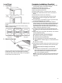
Internet Connectivity Guide for Connected Appliances Only
IMPORTANT: Proper installation of your appliance prior to use is your responsibility. Be sure to read and follow the installation
instructions that came with your appliance.
Connectivity requires Wi-Fi and account creation. App features and functionality are subject to change. Data rates may apply. Once
installed, launch the app. You will be guided through the steps to set up a user account and to connect your appliance.
You Will Need:
n A home wireless router supporting Wi-Fi, 2.4Ghz with WPA2 security. If you are unsure of your router’s capabilities, refer to the router
manufacturer’s instructions.
n The router to be on and have a live internet connection.
n The 10–character SAID code for your appliance. The SAID code is either printed on a label on the appliance or found on the LCD
screen.
Federal Communications Commission (FCC) Compliance Notice
This device complies with Part 15 of the FCC Rules. Operation is subject to the following two conditions:
1. This device may not cause harmful interference, and
2. This device must accept any interference received, including interference that may cause undesired operation.
Changes or modifications not expressly approved by the party responsible for compliance could void the user’s authority to operate the
equipment.
Industry Canada (IC) Compliance Notice
This Device complies with Industry Canada License-exempt RSS standard(s). Operation is subject to the following two conditions:
1. This device may not cause interference.
2. This device must accept any interference, including interference that may cause undesired operation of the device.
Under Industry Canada regulations, this radio transmitter may only operate using an antenna of a type and maximum (or lesser) gain
approved for the transmitter by Industry Canada. To reduce potential radio interference to other users, the antenna type and its gain
should be so chosen that the equivalent isotropically radiated power (e.i.r.p.) is not more than that necessary for successful
communication.
To comply with FCC and Industry Canada RF radiation exposure limits for general population, antenna(s) used for this transmitter must
be installed such that a minimum separation distance of 20 cm is maintained between the radiator (antenna) and all persons at all times
and must not be co-located or operating in conjunction with any other antenna or transmitter.
If this equipment does cause harmful interference to radio or television reception, which can be determined by turning the equipment off
and on, the user is encouraged to try to correct the interference by one of the following measures:
n Reorient or relocate the receiving antenna.
n Increase the separation between the equipment and receiver.
n Connect the equipment into an outlet on a circuit different from that to which the receiver is connected.
n Consult the dealer or an experienced radio/TV technician for help.

5
DRYER MAINTENANCE AND
CARE
Cleaning the Dryer Location
WARNING
Explosion Hazard
Keep flammable materials and vapors, such as gasoline,
away from dryer.
Do not dry anything that has ever had anything
flammable on it (even after washing).
Place dryer at least 18 inches (460 mm) above the floor
for a garage installation.
Failure to do so can result in death, explosion, or fire.
Keep dryer area clear and free from items that would block the
airflow for proper dryer operation. This includes clearing piles of
laundry in front of the dryer.
Cleaning the Dryer Interior
To clean dryer drum:
1. Use nonflammable cleaner or a mild hand dish detergent
mixed at a low concentration with very warm water, and rub
with a soft cloth.
n Rinse well with a wet sponge or towel.
n Tumble a load of clean clothes or towels to dry drum.
OR
2. Use a microfiber cloth and hot water in a spray bottle to clean
the drum and a second microfiber towel to dry.
NOTE: Garments that contain unstable dyes, such as denim blue
jeans or brightly colored cotton items, may discolor the rear of the
dryer interior. These stains are not harmful to your dryer and will
not stain future loads of clothes. Dry unstable dye items inside out
to avoid transfer of dye.
Removing Accumulated Lint
From inside the dryer cabinet:
Lint should be removed every 2 years, or more often, depending
on dryer usage. Cleaning should be done by a qualified appliance
service or ventilation system cleaner.
From the exhaust vent:
Lint should be removed every 2 years, or more often, depending
on dryer usage.
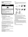
Cleaning the Lint Screen
Every load cleaning:
The lint screen may be located either in the door opening or the
top of the dryer depending on model. A screen blocked by lint can
increase drying time.
To clean:
1. Remove the lint screen. If necessary, press the tab to release
and open the lint screen. Roll lint off the screen with your
fingers. Do not rinse or wash screen to remove lint. Wet lint is
hard to remove.
2. Push the lint screen firmly back into place.
IMPORTANT:
n Do not run the dryer with the lint screen loose, damaged,
blocked, or missing. Doing so can cause overheating and
damage to both the dryer and fabrics.
n If lint falls off the screen into the dryer during removal, check
the exhaust hood and remove the lint. See “Venting
Requirements” in the Installation Instructions.
n Clean space where lint screen is located, as needed. Using a
vacuum, gently remove any lint that has accumulated outside
of the lint screen.
As-needed cleaning:
Laundry detergent and fabric softener residue can build up on the
lint screen. This buildup can cause longer drying times for your
clothes, or cause the dryer to stop before your load is completely
dry. The screen is probably clogged if lint falls off while the screen
is in the dryer. Clean the lint screen with a nylon brush every 6
months, or more frequently, if it becomes clogged due to a residue
buildup.
To wash:
1. Roll lint off the screen with your fingers.
2. Wet both sides of lint screen with hot water.

6
3. Wet a nylon brush with hot water and liquid detergent. Scrub
lint screen with the brush to remove residue buildup.
4. Rinse screen with hot water.
5. Thoroughly dry lint screen with a clean towel. Reinstall screen
in dryer.
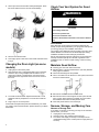
Changing the Drum Light (on some
models)
1. Unplug dryer or disconnect power.
2. Open the dryer door. Locate the light bulb cover on the back
wall of the dryer. Using a Phillips-head screwdriver or 1/4"
(6.35 mm) nut driver or socket wrench, remove the screw
located in the lower right-hand corner of the cover. Remove
the cover.
3. Turn bulb counterclockwise. Replace the bulb with a 10 W
appliance bulb only. Replace the cover and secure with the
screw.
4. Plug in dryer or reconnect power.
Accessories and replacement parts are available for your model.
For ordering and contact information, please reference your Quick
Start Guide.
Check Your Vent System for Good
Airflow
WARNING
Fire Hazard
Use a heavy metal vent.
Do not use a plastic vent.
Do not use a metal foil vent.
Failure to follow these instructions can result in death or
fire.
Good Airflow
Along with heat, dryers require good airflow to efficiently dry
laundry. Proper venting will reduce your drying times and improve
your energy savings. See Installation Instructions.
The venting system attached to the dryer plays a big role in good
airflow. Blocked or crushed vents as well as improper venting
installation will reduce air flow and dryer performance.
Service calls caused by improper venting are not covered by the
warranty and will be paid by the customer, regardless of who
installed the dryer. To clean or repair venting, contact a venting
specialist.
Maintain Good Airflow
n Cleaning your lint screen before each load.
n Replace plastic or foil vent material with 4" (102 mm) diameter
heavy, rigid vent material.
n Use the shortest length of vent possible.
n Use no more than four 90° elbows in a vent system; each bend
and curve reduces airflow.
n Remove lint and debris from the exhaust hood.
n Remove lint from the entire length of the vent system at least
every 2 years. When cleaning is complete, be sure to follow
the Installation Instructions for final product check.
n Clear away items from the front of the dryer.
Nonuse, Storage, and Moving Care
Nonuse or Storage Care
If you will be on vacation or not using your dryer for an extended
period of time, you should:
1. Unplug dryer or disconnect power.
2. Clean lint screen. See “Cleaning the Lint Screen.”
3. Turn off the water supply to the dryer. This helps to avoid
unintended flooding (due to a water pressure surge) while you
are away.

7
Moving Care
For power supply cord-connected dryers:
1. Unplug the power supply cord.
2. Steam models only: Shut off water faucet. Disconnect the
water inlet hose from faucet; then drain the hose. Transport
hose separately.
3. Make sure leveling legs are secure in dryer base.
4. Use tape to secure dryer door.
For direct-wired dryers:
WARNING
Electrical Shock Hazard
Disconnect power before servicing.
Replace all parts and panels before operating.
Failure to do so can result in death or electrical shock.
1. Turn off power at fuse or breaker box.
2. Disconnect wiring.
3. Steam models only: Shut off water faucet.
4. Steam models only: Disconnect the water inlet hose from
faucet; then drain the hose. Transport hose separately.
5. Make sure leveling legs are secure in dryer base.
6. Use tape to secure dryer door.
Special Instructions for Steam
Models
Install and store your dryer where it will not freeze. Because some
water may stay in the hose, freezing can damage your dryer. If
storing or moving your dryer during freezing weather, winterize it.
Water inlet hose
Replace inlet hose and hose screen after 5 years of use to reduce
the risk of hose failure. Periodically inspect and replace inlet hose
if bulges, kinks, cuts, wear, or leaks are found.
When replacing your inlet hose, record the date of replacement.
To winterize the dryer:
1. Unplug dryer or disconnect power.
2. Shut off water faucet.
3. Disconnect water inlet hose from faucet and drain.
To use the dryer again:
1. Flush water pipes. Reconnect water inlet hose to faucet. Turn
on water faucet.
2. Plug in dryer or reconnect power as described in the
Installation Instructions.
Reinstalling the Dryer
Follow the Installation Instructions to locate, level, and connect the
dryer.
INSTALLATION INSTRUCTIONS
REQUIREMENTS
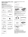
Tools and Parts
NOTE: Install the clothes dryer according to the manufacturer’s
instructions and local codes.
Gather required tools and parts before starting installation. Read
and follow the instructions provided with any tools listed here.
Tools Needed for All Installations:
Flat-blade screwdriver
#2 Phillips screwdriver
1/4” Nut driver
Level
Pliers
Tape measure
Utility knife
Tin snips
Caulking gun and compound
Adjustable wrench that opens
to 1” (25 mm) or hex-head
socket wrench
Wire stripper

8
Additional Tools Needed (on some models):
Putty knife
Parts Supplied (all models):
Leveling legs (4) (Length and appearance of legs may vary
according to model)
Parts package is located in dryer drum. Check that all parts are
included.
NOTE: Do not use leveling legs supplied with dryer if installing
with a pedestal or stack kit.
Parts Needed (steam models):
“Y” connector
2' (0.6 m) inlet hose
Rubber washer
5' (1.52 m) inlet hose
Vented Models:
Vent Clamps, elbows, and vent work
Parts Needed (all models):
Additional parts may be required, depending on your installation.
Check local codes. Check existing electrical supply and venting.
Read “Electrical Requirements” and “Venting Requirements”
before purchasing parts.
Mobile home installations require metal exhaust system hardware
available for purchase from the dealer from whom you purchased
your dryer. For further information, please refer to the Quick Start
Guide for service contact information.
Available Accessories:
Refer to your Quick Start Guide for contact and ordering
information.
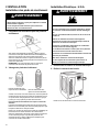
Location Requirements
WARNING
Explosion Hazard
Keep flammable materials and vapors, such as gasoline,
away from dryer.
Do not dry anything that has ever had anything
flammable on it (even after washing).
Place dryer at least 18 inches (460 mm) above the floor
for a garage installation.
Failure to do so can result in death, explosion, or fire.
Check code requirements. Some codes limit, or do not permit,
installing dryer in garages, closets, mobile homes, or sleeping
quarters. Contact your local building inspector.
You will need:
n For vented models: A location allowing for proper exhaust
installation. See “Venting Requirements.”
n A separate 30 A circuit for electric dryers.
n If you are using power supply cord, a grounded electrical outlet
located within 2 ft. (610 mm) of either side of dryer. See
“Electrical Requirements.”
n A sturdy floor to support dryer weight of 200 lbs. (90.7 kg).
Also, consider the combined weight of the companion
appliance.
n For steam dryers: Cold water faucets located within 4 ft. (1.2
m) of the water fill valves, and water pressure of 20–120 psi
(138–827 kPa). You may use the water supply for your washer
using the necessary parts as noted (which you may need to
purchase).
n Level floor with a maximum slope of 1" (25 mm) under the
entire dryer. If the slope is greater than 1" (25 mm), install
Extended Dryer Feet Kit. If not level, clothes may not tumble
properly and automatic sensor cycles may not operate
correctly.
n For garage installation, place dryer at least 18" (460 mm)
above the floor. If using a pedestal, you will need 18" (460 mm)
to bottom of the dryer.
n The dryer must not be installed or stored in an area where it
will be exposed to water and/or weather.
IMPORTANT: Do not operate dryer at temperatures below 45°F
(7°C). Lower temperatures may cause dryer not to shut off at end
of automatic sensor cycles, resulting in longer drying times.
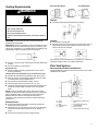
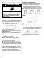
Installation clearances:
For each arrangement, consider allowing more space for ease of
installation and servicing, spacing for companion appliances, and
clearances for walls, doors, and floor moldings. Space must be
large enough to allow the dryer door to fully open. Add spacing on
all sides of the dryer to reduce noise transfer. If a closet door or
louvered door is installed, top and bottom air openings in the door
are required.

9
Installation spacing for a recessed area or closet installation
All dimensions show recommended and minimum spacing
allowed.
n Additional spacing should be considered for ease of
installation and servicing.
n Additional clearances might be required for wall, door, floor,
moldings, dryer venting, and drain system.
n Additional spacing should be considered on all sides of the
dryer to reduce noise transfer.
n For closet installation with a door, minimum ventilation
openings in the top and bottom of the door are required for
vented models. Louvered doors with equivalent ventilation
openings are acceptable.
n Companion appliance spacing should also be considered.
Recommended installation clearances (dryer
only):
*Additional spacing recommended.
Minimum installation clearances (dryer only):
Front Sides Rear Top
Recessed NA 0" (0 mm) 0" (0 mm) 0" (0 mm)
Closet NA 0" (0 mm) 0" (0 mm) 0" (0 mm)
Under
Counter
NA 1" (25 mm) 0" (0 mm) 0" (0 mm)
0" (0 mm) rear spacing is allowed for straight-back venting only.
For steam models only, inlet hose must not be kinked.
Mobile Home – Additional installation
requirements
This dryer is suitable for mobile home installations. The
installation must conform to the Manufactured Home Construction
and Safety Standard, Title 24 CFR, Part 3280 (formerly the
Federal Standard for Mobile Home Construction and Safety, Title
24, HUD Part 280) or the Standard for Mobile Homes, CAN/CSA-
Z240 MH.
Mobile home installations require:
n Metal exhaust system hardware, which is available for
purchase from your dealer.
n Special provisions must be made in mobile homes to introduce
outside air into the dryer. The opening (such as a nearby
window) should be at least twice as large as the dryer exhaust
opening.
Electrical Requirements – U.S.A.
It is your responsibility:
n To contact a qualified electrical installer.
n To be sure that the electrical connection is adequate and in
conformance with the National Electrical Code, ANSI/ NFPA
70 – latest edition and all local codes and ordinances. The
National Electrical Code requires a 4-wire power supply
connection for homes built after 1996, dryer circuits involved in
remodeling after 1996, and all mobile home installations. A
copy of the above code standards can be obtained from:
National Fire Protection Association, One Batterymarch Park,
Quincy, MA 02169–7471.
n To supply the required 3- or 4-wire, single-phase, 120/240 V,
60 Hz, AC-only electrical supply (or 3- or 4-wire, 120/208 V
electrical supply, if specified on the serial/rating plate) on a
separate 30 A circuit, fused on both sides of the line. Connect
to an individual branch circuit. Do not have a fuse in the neutral
or grounding circuit.
n Do not use an extension cord.
n If codes permit and a separate ground wire is used, it is
recommended that a qualified electrician determine that the
ground path is adequate.
Electrical Connection
To properly install your dryer, you must determine the type of
electrical connection you will be using and follow the instructions
provided for it here.
n This dryer is manufactured ready to install with a 3-wire
electrical supply connection. The neutral ground conductor is
permanently connected to the neutral conductor (white wire)
within the dryer. If the dryer is installed with a 4-wire electrical
supply connection, the neutral ground conductor must be
removed from the external ground connector (green screw),
and secured under the neutral terminal (center or white wire)
of the terminal block. When the neutral ground conductor is
secured under the neutral terminal (center or white wire) of the
terminal block, the dryer cabinet is isolated from the neutral
conductor. The green ground wire of the 4-wire power cord
must be secured to the dryer cabinet with the green ground
screw
n If local codes do not permit the connection of a neutral ground
wire to the neutral wire, see “Optional 3-Wire Connection.”
n A 4-wire power supply connection must be used when the
appliance is installed in a location where grounding through
the neutral conductor is prohibited. Grounding through the
neutral conductor is prohibited for (1) new branch-circuit
installations after 1996, (2) mobile homes, (3) recreational
vehicles, and (4) areas where local codes prohibit grounding
through the neutral conductors.
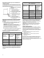
If using a power supply cord:
Use a UL-listed power supply cord kit marked for use with clothes
dryers. The kit should contain:
n A UL-listed 30 A power supply cord, rated 120/240 V
minimum. The cord should be type SRD or SRDT and be at
least 4 ft. (1.22 m) long. The wires that connect to the dryer
must end in ring terminals or spade terminals with upturned
ends.
n A UL-listed strain relief.

10
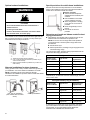
If your outlet looks like this:
4-wire receptacle
(14-30R)
Then choose a 4-wire power supply cord
with ring or spade terminals and UL-listed
strain relief. The 4-wire power supply cord,
at least 4 ft. (1.22 m) long, must have four
10-gauge copper wires and match a 4-wire
receptacle of NEMA Type 14-30 R. The
ground wire (ground conductor) may be
either green or bare. The neutral
conductor must be identified by a white
cover.
If your outlet looks like this:
3-wire receptacle
(10-30R)
Then choose a 3-wire power supply cord
with ring or spade terminals and UL-listed
strain relief. The 3-wire power supply cord,
at least 4 ft. (1.22 m) long, must have three
10-gauge copper wires and match a 3-wire
receptacle of NEMA Type 10-30R.
If connecting by direct wire:
Power supply cable must match power supply (4-wire or 3-wire)
and be:
Flexible armored cable or nonmetallic sheathed copper cable
(with ground wire), covered with flexible metallic conduit. All
current-carrying wires must be insulated.
10-gauge solid copper wire (do not use aluminum) at least 5 ft.
(1.52 m) long.
GROUNDING INSTRUCTIONS
For a grounded, cord-connected appliance:
This appliance must be grounded. In the event of a
malfunction or breakdown, grounding will reduce the risk of
electric shock by providing a path of least resistance for
electric current. This appliance is equipped with a cord having
an equipment-grounding conductor and a grounding plug.
The plug must be plugged into an appropriate outlet that is
properly installed and grounded in accordance with all local
codes and ordinances.
WARNING: Improper connection of the equipment-
grounding conductor can result in a risk of electric shock.
Check with a qualified electrician or service representative if
you are in doubt as to whether the appliance is properly
grounded. Do not modify the plug provided with the
appliance: If it will not fit the outlet, have a proper outlet
installed by a qualified electrician.
For a permanently connected appliance:
This appliance must be connected to a grounded metal,
permanent wiring system, or an equipment-grounding
conductor must be run with the circuit conductors and
connected to the equipment-grounding terminal or lead on
the appliance.
SAVE THESE INSTRUCTIONS
Electric Requirements – Canada
WARNING
Electrical Shock Hazard
Plug into a grounded 4 prong outlet.
Failure to do so can result in death or electrical shock.
It is your responsibility:
To contact a qualified electrical installer.
To be sure that the electrical connection is adequate and in
conformance with Canadian Electrical Code, C22.1 – latest
edition and all local codes. A copy of above codes standard
may be obtained from: Canadian Standards Association, 178
Rexdale Blvd., Toronto, ON M9W 1R3 CANADA.
To supply the required 4-wire, single-phase, 120/240 V, 60 Hz,
AC-only electrical supply on a separate 30 A circuit, fused on
both sides of the line. A time-delay fuse or circuit breaker is
recommended. Connect to an individual branch circuit.
This dryer is equipped with a UL-listed and/or CSA
International Certified Power Cord intended to be plugged into
a standard 14-30R wall receptacle. The cord is 5 ft. (1.52 m)
long. Be sure wall receptacle is within reach of dryer’s final
location.
4-wire receptacle (14-30R)
If codes permit and a separate ground wire is used, it is
recommended that a qualified electrician determine that the
ground path is adequate.
Do not use an extension cord.
For further information, or to obtain a Power Supply Cord
Replacement (Part Number W11095079), please reference the
contact information listed on your Quick Start Guide.
GROUNDING INSTRUCTIONS
For a grounded, cord-connected appliance:
This appliance must be grounded. In the event of a
malfunction or breakdown, grounding will reduce the risk of
electric shock by providing a path of least resistance for
electric current. This appliance is equipped with a cord having
an equipment-grounding conductor and a grounding plug.
The plug must be plugged into an appropriate outlet that is
properly installed and grounded in accordance with all local
codes and ordinances.
WARNING: Improper connection of the equipment-
grounding conductor can result in a risk of electric shock.
Check with a qualified electrician or service representative if
you are in doubt as to whether the appliance is properly
grounded. Do not modify the plug provided with the
appliance: if it will not fit the outlet, have a proper outlet
installed by a qualified electrician.
SAVE THESE INSTRUCTIONS

11
INSTALLATION
Install Leveling Legs
WARNING
Excessive Weight Hazard
Use two or more people to move and install or uninstall
appliance.
Failure to do so can result in back or other injury.
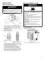
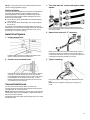
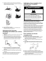
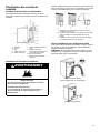
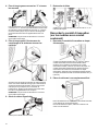
1. Prepare dryer for leveling legs
To avoid damaging floor, use a large flat piece of cardboard
from dryer carton; place under entire back edge of dryer.
Firmly grasp dryer body (not console panel) and gently lay
dryer down on cardboard.
NOTE: Residual water from factory testing may drain when
dryer is laying on its side.
2. Screw in leveling legs
Leveling leg with diamond
marking.
Leveling leg without diamond
marking
Using a wrench and tape measure, screw leveling legs into
leg holes until bottom of foot is approximately 1/2" (13 mm) to
1 1/2" (38 mm) from bottom of the dryer.
For leveling legs with the diamond marking:
Screw legs into leg holes by hand. Use a wrench to finish
turning legs until diamond marking is no longer visible.
Place a carton corner post from dryer packaging under each
of the two dryer back corners. Stand the dryer up. Slide the
dryer on the corner posts until it is close to its final location.
Leave enough room to connect the exhaust vent.
Electrical Installation – U.S.A.
WARNING
Fire Hazard
For power supply cord, use a new UL listed 30 A power
supply cord.
For direct wire, use 10 gauge copper wire.
Use a UL listed strain relief.
Disconnect power before making electrical connections.
Connect neutral wire (white or center wire) to center
terminal (silver).
Connect ground wire (green or bare wire) to green
ground connector.
Connect remaining 2 supply wires to remaining 2
terminals (gold).
Securely tighten all electrical connections.
Failure to do so can result in death, fire, or electrical
shock.
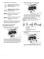
1. Disconnect power
2. Remove terminal block cover
Remove hold-down screw and terminal block cover.

12
3. Choose electrical connection type
Power supply cord 4-wire receptacle
(NEMA Type 14-30R): Go to “4-Wire Power
Supply Cord Connection.” Then, go to
“Venting Requirements.”
Power supply cord 3-wire receptacle
(NEMA Type 10-30R): Go to “3-Wire Power
Supply Cord Connection.” Then, go to
“Venting Requirements.”
4-wire direct connection: Go to “Direct Wire
Strain Relief,” then “4-Wire Direct Wire
Connection,” then, go to “Venting
Requirements.”
3-wire direct connection: Go to “Direct Wire
Strain Relief”, then “3-Wire Direct Wire
Connection,” then, go to “Venting
Requirements.”
NOTE: If local codes do not permit connection of a cabinet-
ground conductor to neutral wire, go to “Optional 3-wire
Connection.” This connection may be used with either a
power supply cord or a direct wire connection.
Power Supply Cord Connection
Power Supply Cord Strain Relief
1. Attach power supply cord strain relief
Remove the screws from a 3/4" (19 mm) UL-listed strain relief
(UL marking on strain relief). Put the tabs of the two clamp
sections (C) into the hole below the terminal block opening
(B) so that one tab is pointing up (A) and the other is pointing
down (D), and hold in place. Tighten strain relief screws just
enough to hold the two clamp sections (C) together.
2. Attach power supply cord to strain relief
Put power supply cord through the strain relief. Be sure that
the wire insulation on the power supply cord is inside the
strain relief. The strain relief should have a tight fit with the
dryer cabinet and be in a horizontal position. Do not further
tighten strain relief screws at this point.
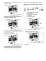
4-Wire Power Supply Cord Connection
IMPORTANT: A 4-wire connection is required for mobile homes
and where local codes do not permit the use of 3-wire
connections.
A. 4-wire receptacle (NEMA type 14-30R)
B. 4-prong plug
C. Ground prong
D. Neutral prong
E. Spade terminals with upturned ends
F. 3/4" (19 mm) UL-listed strain relief
G. Ring terminals
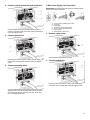
3. Prepare to connect neutral ground wire and
neutral wire
Remove center terminal block screw (B). Remove neutral
ground wire (E) from green external ground conductor screw
(A).

13
4. Connect neutral ground wire and neutral wire
Connect neutral ground wire (E) and neutral wire (white or
center) (C) of power supply cord under center terminal block
screw (B). Tighten screw.
5. Connect ground wire
Connect ground wire (F) (green or bare) of power supply cord
under green external ground conductor screw (A). Tighten
screw.
6. Connect remaining wires
Connect remaining wires under outer terminal block screws.
Tighten screws. Insert tab of terminal block cover into slot of
dryer rear panel. Secure cover with hold-down screw. Now,
go to “Venting Requirements.”
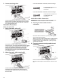
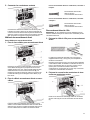
3-Wire Power Supply Cord Connection
IMPORTANT: Use where local codes permit connecting cabinet-
ground conductor to neutral wire.
A. 3-wire receptacle (NEMA type 10-30R)
B. 3-wire plug
C. Neutral prong
D. Spade terminals with upturned ends
E. 3/4" (19 mm) UL-listed strain relief
F. Ring terminals
G. Neutral (white or center wire)
3. Remove center screw
Remove center terminal block screw (B).
4. Connect neutral wire
Connect neutral wire (white or center) (C) of power supply
cord under center terminal block screw (B). Tighten screw.

14
5. Connect remaining wires
Connect remaining wires under outer terminal block screws.
Tighten screws. Insert tab of terminal block cover into slot of
dryer rear panel. Secure cover with hold-down screw. Now,
go to “Venting Requirements.”
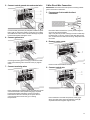
Direct Wire Connection
Direct wire strain relief
1. Attach direct wire strain relief
Unscrew the removable conduit connector (A) and any
screws from a 3/4" (19 mm) UL-listed strain relief (UL marking
on strain relief). Put the threaded section of the strain relief
through the hole below the terminal block opening (B).
Reaching inside the terminal block opening, screw the
removable conduit connector (A) onto the strain relief threads
(C) and tighten securely.
2. Attach direct wire cable to strain relief
Put direct wire cable through the strain relief. The strain relief
should have a tight fit with the dryer cabinet and be in a
horizontal position. Tighten strain relief screw against the
direct wire cable.
For 4-wire Direct Wire Connection, continue to step 3.
4-wire direct wire connection: Go
to “4-Wire Direct Wire
Connection.”
For 3-wire Direct Wire Connection, continue to step 3.
3-wire direct wire connection: Go
to “3-Wire Direct Wire
Connection.”
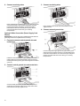
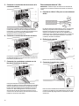
4-Wire Direct Wire Connection
IMPORTANT: A 4-wire connection is required for mobile homes
and where local codes do not permit 3-wire connections.
3. Prepare your 4-wire cable for direct
connection
Direct wire cable must have 5 ft. (1.52 m) of extra length so
dryer may be moved if needed.
Strip 5" (127 mm) of outer covering from end of cable, leaving
bare ground wire at 5" (127 mm). Cut 1 1/2" (38 mm) from
remaining 3 wires. Strip insulation back 1" (25 mm). Shape
ends of wires into hooks.
4. Prepare to connect neutral ground wire and
neutral wire
Remove center terminal block screw (B). Remove neutral
ground wire (E) from green external ground conductor screw
(A).

15
5. Connect neutral ground wire and neutral wire
Connect neutral ground wire (E) and place hooked end (hook
facing right) of neutral wire (white or center wire) (C) of direct
wire cable under center screw of terminal block (B). Squeeze
hooked ends together and tighten screw.
6. Connect ground wire
Connect ground wire (green or bare) (F) of direct wire cable
under green external ground conductor screw (A). Tighten
screw.
7. Connect remaining wires
Place hooked ends of remaining direct wire cable wires under
outer terminal block screws (hooks facing right). Squeeze
hooked ends together and tighten screws. Insert tab of
terminal block cover into slot of dryer rear panel. Secure
cover with hold-down screw. Now, go to “Venting
Requirements.”
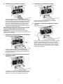
3-Wire Direct Wire Connection
IMPORTANT: Use where local codes permit connecting cabinet-
ground conductor to neutral wire.
3. Prepare your 3-wire cable for direct
connection
Direct wire cable must have 5 ft. (1.52 m) of extra length so
dryer may be moved if needed.
Strip 3 1/2" (89 mm) of outer covering from end of cable. Strip
insulation back 1" (25 mm). If using 3-wire cable with ground
wire, cut bare wire even with outer covering. Shape wire ends
into hooks.
4. Remove center screw
Remove center terminal block screw (B).
5. Connect neutral wire
Place hooked end of neutral wire (white or center) (C) of
direct wire cable under center terminal block screw (B).
Squeeze hooked end together. Tighten screw.

16
6. Connect remaining wires
Place hooked ends of remaining direct wire cable wires under
outer terminal block screws (hooks facing right). Squeeze
hooked ends together and tighten screws. Insert tab of
terminal block cover into slot of dryer rear panel. Secure
cover with hold-down screw. Now, go to “Venting
Requirements.”
Optional 3-Wire Connection (Power Supply Cord
Shown)
IMPORTANT: You must verify with a qualified electrician that this
grounding method is acceptable before connecting.
1. Prepare to connect neutral ground wire and
neutral wire
Install the correct strain relief for your electrical connection
method. Remove center terminal block screw (B). Remove
neutral ground wire (E) from green external ground conductor
screw (A).
2. Connect neutral ground wire and neutral wire
Connect neutral ground wire (E) and neutral wire (white or
center wire) (C) of power supply cord or cable under center
terminal block screw (B). Tighten screw.
3. Connect remaining wires
Place remaining wires under outer terminal block screws.
Tighten screws.
4. Connect external ground wire
Connect a separate copper ground wire (G) from the green
external ground conductor screw (A) to an adequate ground.
Insert tab of terminal block cover into slot of dryer rear panel.
Secure cover with hold-down screw. Now, go to “Venting
Requirements.”

17
Venting Requirements
WARNING
Fire Hazard
Use a heavy metal vent.
Do not use a plastic vent.
Do not use a metal foil vent.
Failure to follow these instructions can result in death or
fire.
WARNING: To reduce the risk of fire, this dryer MUST BE
EXHAUSTED OUTDOORS.
IMPORTANT: Observe all governing codes and ordinances. Dryer
exhaust must not be connected into any gas vent, chimney, wall,
ceiling, attic, crawlspace, or a concealed space of a building. Only
rigid or flexible metal vent shall be used for exhausting.
n Only a 4" (102 mm) heavy metal exhaust vent and clamps may
be used.
n Do not use plastic or metal foil vent.
Rigid metal vent:
n Recommended for best drying performance and to avoid
crushing and kinking.
Flexible metal vent (acceptable only if accessible to clean):
n Must be fully extended and supported in final dryer location.
n Remove excess to avoid sagging and kinking that may result
in reduced airflow and poor performance.
n Do not install in enclosed walls, ceilings, or floors.
n The total length should not exceed 7 3/4 ft. (2.4 m).
n The length of flexible metal vent used must be included in the
overall vent system design as shown in the “Vent System
Chart.”
NOTE: If using an existing vent system, clean lint from entire
length of the system and make sure exhaust hood is not plugged
with lint. Replace plastic or metal foil vents with rigid metal or
flexible metal vents. Review “Vent System Chart” and, if
necessary, modify existing vent system to achieve best drying
performance.
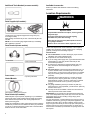
Exhaust hoods:
n An exhaust hood should cap the vent to keep rodents and
insects from entering the home.
n Must be at least 12" (305 mm) from ground or any object that
may obstruct exhaust (such as flowers, rocks, bushes, or
snow).
n Do not use an exhaust hood with a magnetic latch.
Recommended Styles: Acceptable Style:
Louvered Hood
Box Hood
Angled Hood
Elbows:
n 45° elbows provide better airflow than 90° elbows.
Clamps:
n Use clamps to seal all joints.
n Exhaust vent must not be connected or secured with screws or
other fastening devices that extend into interior of duct and
catch lint. Do not use duct tape.
Vent products can be purchased from your dealer. For contact and
ordering information, refer to your Quick Start Guide.
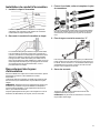
Plan Vent System
Recommended exhaust installations:
Typical installations vent the dryer from the rear of the dryer. Other
installations are possible.
A. Dryer
B. Elbow
C. Wall
D. Exhaust hood
E. Clamps
F. Rigid metal or flexible metal
vent
G. Vent length necessary to
connect elbows
H. Exhaust outlet
I. Optional side exhaust outlet

18
Optional exhaust installations:
WARNING
Fire Hazard
Cover unused exhaust holes with a manufacturer’s
exhaust cover kit.
Contact your local dealer.
Failure to follow these instructions can result in death,
fire, electrical shock, or serious injury.
Some models can be converted to exhaust out the right side, left
side, or through the bottom. If you prefer, you may contact your
local dealer to have the dryer converted.
A. Standard rear offset exhaust installation
B. Left- or right-side exhaust installation (available only on
select 27"-wide models).
C. Bottom exhaust installation (available only on select 27"-
wide models).
Alternate installations for close clearances
Venting systems come in many varieties. Select the type best for
your installation. Two close-clearance installations are shown.
NOTE: The following kits for close-clearance alternate
installations are available for purchase. Refer to Quick Start Guide
for contact information.
Over-The-Top installation
(also available with one offset
elbow)
Periscope installation
Special provisions for mobile home installations:
Exhaust vent must be securely fastened to a noncombustible
portion of the mobile home and must not terminate beneath the
mobile home. Terminate exhaust vent outside.
Determine vent path:
n Select route that will provide
straightest and most direct path
outdoors.
n Plan installation to use fewest
number of elbows and turns.
n When using elbows or making
turns, allow as much room as
possible.
n Bend vent gradually to avoid
kinking.
n Use as few 90° turns as
possible.
Determine vent length and elbows needed for best
drying performance:
n Use following “Vent System Chart” to determine type of vent
material and hood combinations acceptable to use.
NOTE: Do not use vent runs longer than those specified in
“Vent System Chart.” Exhaust systems longer than those
specified will:
n Shorten life of dryer.
n Reduce performance, resulting in longer drying times and
increased energy usage.
The “Vent System Chart” provides venting requirements that will
help achieve best drying performance.
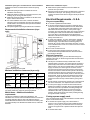
Vent System Chart
Number of 90°
turns or elbows
Type of vent
Box/louvered or
Angled hoods
0
Rigid metal 64 ft. (20 m)
1
Rigid metal 54 ft. (16.5 m)
2
Rigid metal 44 ft. (13.4 m)
3
Rigid metal 35 ft. (10.7 m)
4
Rigid metal 27 ft. (8.2 m)
NOTE: Side and bottom exhaust installations have a 90º turn
inside the dryer. To determine maximum exhaust length, add one
90º turn to the chart.
Vent System Chart (Long Vent Models)
Number of 90°
turns or elbows
Type of vent Box/louvered or
Angled hoods
0 Rigid metal 160 ft. (48.8 m)
1 Rigid metal 150 ft. (45.7 m)
2 Rigid metal 140 ft. (42.7 m)
3 Rigid metal 130 ft. (39.6 m)
4 Rigid metal 120 ft. (36.6 m)
5 Rigid metal 110 ft. (33.5 m)
To determine if your model has a long vent system, refer to the
type code located on the serial number plate in the inner door
well. Example: A Long Vent Model would be BJAV-NAT-
XXXXXXX-XXX or BWFB-NAT-XXXXXXX-XXX.

19
NOTE: For long vent systems, use of box/louvered hoods will
improve venting regardless of length.
Additional Elbows
In cases in which the Installation Instructions do not address the
vent length for the specific number of elbows required for a
particular application, the following calculations may be used.
(The total vent system length includes all straight and curved
portions of the vent system):
n For 90° elbows, reduce the allowable vent system length by
10 Ft. (3.05 m).
n For 45° elbows, reduce the allowable vent system length by
6 Ft. (1.83 m).
For example, if the Installation Instructions state that a dryer is
allowed 40 Ft. (12.2 m) of total vent length with two 90° bends, the
total allowable vent length would be reduced by 10 Ft. (3.0 m)
(from 40 Ft [12.2 m] to 30 Ft. [9.1m]).
Install Vent System
1. Install exhaust hood
Install exhaust hood and use caulking compound to seal
exterior wall opening around exhaust hood.
2. Connect vent to exhaust hood
Vent must fit over the exhaust hood. Secure vent to exhaust
hood with 4" (102 mm) clamp. Run vent to dryer location
using straightest path possible. Avoid 90° turns. Use clamps
to seal all joints. Do not use duct tape, screws, or other
fastening devices that extend into interior of vent to secure
vent, because they can catch lint.
Connect Inlet Hoses
For vented, non-steam models, skip to “Connect Vent.”
The dryer must be connected to the cold water faucet using the
new inlet hoses. Do not use old hoses.
NOTE: Replace inlet hoses after 5 years of use to reduce the risk
of hose failure. Record hose installation or replacement dates on
the hoses for future reference.
Periodically inspect and replace hoses if bulges, kinks, cuts, wear,
or leaks are found.
1. Turn cold water off, remove and replace rubber
washer
Turn cold water faucet off and remove washer inlet hose.
Remove old rubber washer from inlet hose and replace with
new rubber washer.
2. Attach short hose and “Y” connector
Attach 2 ft. (0.6 m) inlet hose to cold water faucet. Screw on
coupling by hand until it is seated on faucet. Then attach “Y”
connector to male end of the 2 ft. (0.6 m) inlet hose. Screw on
coupling by hand until it is seated on connector.
3. Tighten couplings
Using pliers, tighten the couplings with additional two-thirds
turn.
NOTE: Do not overtighten. Damage to the coupling can
result.

20
4. Attach long hose to “Y” connector and tighten
couplings
Attach one of the 5 ft. (1.5 m) inlet hose ends to the “Y”
connector. Attach washer cold inlet hose to other side of “Y”
connector. Screw on coupling by hand until it is seated on
connector. Using pliers, tighten the couplings an additional
two-thirds turn.
NOTE: Do not overtighten. Damage to the coupling can
result.
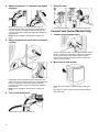
5. Attach long hose to dryer fill valve and tighten
coupling
If applicable, remove protective cap from water inlet valve.
Attach other end of long hose to fill valve on dryer back panel.
Screw on coupling by hand until it is seated on fill valve
connector. Using pliers, tighten the couplings an additional
two-thirds turn.
NOTE: Do not overtighten. Damage to the coupling can
result.
6. Turn on cold water faucet
Check that the water faucet is turned on.
7. Check for leaks
Check for leaks around “Y” connector, faucets, and hoses.
Connect Vent (Vented Models Only)
1. Connect vent to exhaust outlet
Using a 4" (102 mm) clamp, connect vent to exhaust outlet in
dryer. If connecting to existing vent, make sure vent is clean.
Dryer vent must fit over dryer exhaust outlet and inside
exhaust hood. Check that vent is secured to exhaust hood
with a 4" (102 mm) clamp.
2. Move dryer to final location
Move dryer to final location. Avoid crushing or kinking the
vent.
After dryer is in place, remove corner posts and cardboard
from under dryer.
La page est en cours de chargement...
La page est en cours de chargement...
La page est en cours de chargement...
La page est en cours de chargement...
La page est en cours de chargement...
La page est en cours de chargement...
La page est en cours de chargement...
La page est en cours de chargement...
La page est en cours de chargement...
La page est en cours de chargement...
La page est en cours de chargement...
La page est en cours de chargement...
La page est en cours de chargement...
La page est en cours de chargement...
La page est en cours de chargement...
La page est en cours de chargement...
La page est en cours de chargement...
La page est en cours de chargement...
La page est en cours de chargement...
La page est en cours de chargement...
La page est en cours de chargement...
La page est en cours de chargement...
La page est en cours de chargement...
-
 1
1
-
 2
2
-
 3
3
-
 4
4
-
 5
5
-
 6
6
-
 7
7
-
 8
8
-
 9
9
-
 10
10
-
 11
11
-
 12
12
-
 13
13
-
 14
14
-
 15
15
-
 16
16
-
 17
17
-
 18
18
-
 19
19
-
 20
20
-
 21
21
-
 22
22
-
 23
23
-
 24
24
-
 25
25
-
 26
26
-
 27
27
-
 28
28
-
 29
29
-
 30
30
-
 31
31
-
 32
32
-
 33
33
-
 34
34
-
 35
35
-
 36
36
-
 37
37
-
 38
38
-
 39
39
-
 40
40
-
 41
41
-
 42
42
-
 43
43


Maytag MED5630HW Le manuel du propriétaire
- Catégorie
- Sèche-linge électriques
- Taper
- Le manuel du propriétaire
dans d''autres langues
- English: Maytag MED5630HW Owner's manual