
On/Off Outlet
Owner’s Manual
On/Off Outlet
Owner’s Manual

Contents
Getting Started
Insteon Wall Outlet 4
On/O Outlet
Buttons
Tools Needed for Installation
Disconnect Power
Installation Timeline
Installation 6
Installation Diagrams
End-of-Run Outlet 10
Middle-of-Run Outlet 11
Switched Outlet 12
Insteon Links
Understanding Linking 15
Adding to the Insteon Hub 17
Software-Only Features
Beep on Button Press 19
Blink on Trac
Disable Local Programming
Error Blink
LED Brightness 20
Local Programming
Flow Chart 23
LED Brightness 24
RF Beacon
Load Sense 25
Soft Factory Reset 26
Factory Reset
Factory Reset 28
Appendix
Specications 30
Troubleshooting 33
Certications and Warnings 35
Product Warranty 36

3
Everything you need to quickly get up and running.
Getting Started
Everything you need to quickly get up and running.
Getting Started

4
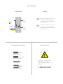
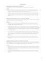
Buttons
Tap to turn the lower outlet on or o.
See sections on Basic Linking and
Local Programming for additional set
button functions.
Tap to turn the upper outlet on or o.
See sections on Basic Linking and
Local Programming for additional set
button functions.
On/O Outlet
Insteon Wall Outlet
Tools Needed for Installation Disconnect Power
Phillips Screwdriver
Wire Cutter / Stripper
Voltage Detector
Flathead Screwdriver
Always disconnect power before
installation. Contact Insteon
Support when uncertain about
installation.
1-866-243-8022
Lower
Outlet
Tamper
Resistant
Upper
Outlet
Tamper
Resistant
Lower
Upper
Status LEDs
On/O &
Set Buttons
On
O

55
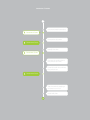
Installation Timeline
Unbox and read instructions
Remove the old outlet
Identify Line wire
Install wall plate
Carefully install the outlet into
the junction box
Connect the outlet wires to
the junction box wires
Test the outlet by tapping a
set button to turn on
Disconnect Power
Reconnect Power
Disconnect Power
Reconnect Power
Installation Timeline
Unbox and read instructions
Remove the old outlet
Identify Line wire
Install wall plate
Connect the outlet wires to
the junction box wires
Carefully install the outlet into
the junction box
Test the outlet by tapping a
set button to turn on
Disconnect Power
Reconnect Power
Disconnect Power
Reconnect Power

6
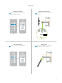
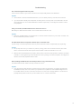
Identify LineReconnect Power
Disconnect Power Remove the Old Outlet
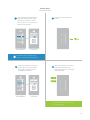
Installation
Turn o power to your outlet at the
electrical service panel.
Remove the old outlet and disconnect
the wires.
Use a voltage detector to identify the
line wire. Line will be energized.
Turn on power at the circuit breaker.
1 2
43
ON
ON
ON
ON
ON
ON
ON
ON
ON ON
ON ON
Circuit Breakers
Circuit Breakers
Fuse Panel
Fuse Panel
or
or
½”
12mm
1 2

7
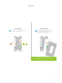
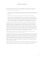
Reconnect PowerInstall the Outlet
Wire-In the Outlet
Installation
Turn o power at the circuit breaker. Connect the Outlet wires to the identied wires in the junction box.
Verify that the wire nuts are secure and that no exposed copper wire is visible. Additional wiring diagrams
can be found in the Installation Diagrams section.
Turn power on to the outlet at the circuit
breaker panel.
Mount the Outlet into the junction box.
5
76
ON
ON
ON
ON
ON
ON
ON
ON
ON ON
Circuit Breakers Fuse Panel
or
Neutral
Ground
Line


9
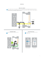
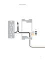
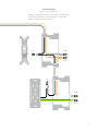
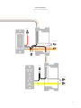
Use the installation diagrams in this section to help you wire
your Wall Outlet.
Installation Diagrams
Use the installation diagrams in this section to help you wire
your Wall Outlet.
Installation Diagrams

10
Line
Neutral
Ground
End-of-Run Outlet

11
Line
Neutral
Ground
Middle-of-Run Outlet

12
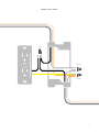
Line
Line
Neutral
Neutral
Ground
Ground
Switched Outlet
Without Insteon Wall Switch
Replacing a switched outlet requires removing the wall switch from
the circuit. The wall switch can be replaced by an Insteon Wall
Switch or Keypad if control is still desired.

13
Line
Line
Neutral
Neutral
Ground
Ground
Switched Outlet
With Insteon Wall Keypad

14
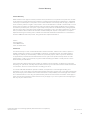
Chapter explanation
Chapter Title
Insteon devices can stand alone and function as a local switch or dimmer,
but their real power comes when they are connected together to form a
control system. Most Insteon devices can control one another and be the
recipient of control. The process of associating multiple Insteon devices to
one another is called Linking.
Insteon Links

15
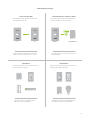
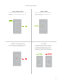
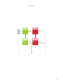
When linking Insteon devices, the links that
are created are one-way.
The current state of the controlled device is
stored in the link: On, o or dimmed.
Switch A will turn Switch B on and o but
Switch B cannot turn Switch A on or o.
The switch will turn on the Lamp Dimmer to
75% brightness.
A SwitchB Lamp Dimmer
NEW
X
NEW
X
75%
Insteon devices that can turn other devices on
or o are called controllers.
Sensors, Switches, Keypads and the
Hub are common controllers.
NEW
X
Insteon devices that receive the command of a
controller are called responders.
Switches, Keypads, Plug-In Modules and
LED Bulbs are common responders.
NEW
X
RespondersControllers
Links Remember a Device’s StateLinks are One-Way
Understanding Linking
b
c
d
a

16
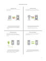
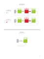
Controller-Only
Some devices, like sensors, can only control
other devices.
The Motion Sensor will turn on the Switch
but the switches cannot control the Motion
Sensor.
NEW
X
Responder-Only
Some devices cannot control other devices;
these devices only receive Insteon commands.
Some devices can only link as
responders to devices and scenes.
LED Bulb Dimmer Switch
NEW
X
Understanding Linking
Grouping Devices Use Cross Linking
You may want to group together two
devices, for example, in a virtual-three way
conguration. For Insteon, this is called Cross
Linking.
To Cross Link, simply turn on the devices and
perform the linking process twice, once in
each direction.
To mirror Switch A and B so that they each
control one another and the connected
load, Cross Linking is necessary.
Link Switch A to Switch B and repeat to link
Switch B to Switch A.
NEW
X
NEW
X
A BLoad
Motion Sensor Dimmer Switch
A B

17
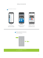
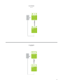
Adding to the Insteon Hub
iOS Android Windows Phone
1
2
Tap the Add a Device button.
Open the drawer by
swiping from the right
side of your iOS device
Navigate to All Devices
from Rooms on your
Android device
Navigate to All Devices
from Rooms on your
Windows Phone device
When prompted, press and hold one
of the set buttons on your Wall Outlet
until the device beeps.
Your Wall Outlet is now added to
your Insteon Hub.

18
Chapter explanation
Chapter Title
Most Insteon devices contain features that can only be enabled, disabled
or modied using Insteon control software such as HouseLinc and an
Insteon PowerLine Modem.
Software-Only Features
Most Insteon devices contain features that can only be enabled, disabled
or modied using Insteon control software such as HouseLinc and an
Insteon PowerLine Modem.
Software-Only Features

19
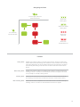
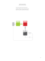
The Wall Outlet LED will blink if it detects
Insteon communication. By default, this
feature is disabled.
Prevents changing any settings using the set
button or tap-and-hold programming.
Software-Only Features
Beep on Button Press Blink on Trac
Disable Local Programming Error Blink
The Wall Outlet LED will blink red once if one
or more responders do not acknowledge
a message and will blink green once if all
responders successfully acknowledge a
message. By default, this feature is enabled.
The Wall Outlet will beep every time one of its
buttons are tapped. By default, this feature is
disabled.

20
Adjust the brightness of the status LEDs from
full bright to o.
LED Brightness
Software-Only Features
La page est en cours de chargement...
La page est en cours de chargement...
La page est en cours de chargement...
La page est en cours de chargement...
La page est en cours de chargement...
La page est en cours de chargement...
La page est en cours de chargement...
La page est en cours de chargement...
La page est en cours de chargement...
La page est en cours de chargement...
La page est en cours de chargement...
La page est en cours de chargement...
La page est en cours de chargement...
La page est en cours de chargement...
La page est en cours de chargement...
La page est en cours de chargement...
-
 1
1
-
 2
2
-
 3
3
-
 4
4
-
 5
5
-
 6
6
-
 7
7
-
 8
8
-
 9
9
-
 10
10
-
 11
11
-
 12
12
-
 13
13
-
 14
14
-
 15
15
-
 16
16
-
 17
17
-
 18
18
-
 19
19
-
 20
20
-
 21
21
-
 22
22
-
 23
23
-
 24
24
-
 25
25
-
 26
26
-
 27
27
-
 28
28
-
 29
29
-
 30
30
-
 31
31
-
 32
32
-
 33
33
-
 34
34
-
 35
35
-
 36
36


dans d''autres langues
- English: INSTEON 2663-222 User manual
Documents connexes
-
INSTEON Remote Control Plug-In Lamp Dimmer Module Manuel utilisateur
-
-
-
-
-
-
-
-
-
