Extron DTP T SW4 HD 4K Manuel utilisateur
- Taper
- Manuel utilisateur

DTPTSW4HD4K • Setup Guide
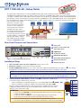
The Extron DTPTSW4HD4K is a four input HDMI switcher with a DTP output that switches and extends digital
embedded audio, bidirectional RS-232 and IR control remote power, and HDMI video signals up to 330
feet (100
meters).
It
is an HDCP-compliant switcher, that supports video resolutions up to 4K@30Hz (or 4K@60Hz at 4:2:0), using shielded twisted
pair cabling as a transmission medium. The switcher features four HDMI inputs, with a DTP/HDBT output, so it can be integrated
into many applications that use a DTP equipped receiver, or HDBT capable products. The switcher also features Contact/Tally
ports which are used in tandem
with Extron “Show Me” cables,
when used in Extron TeamWork
systems. For easy integration,
remote power for the end unit is
available via the DTP output.
This guide provides instructions
for an experienced installer to
set up and operate this switcher.
For full installation, conguration,
and operation details, see the
DTPTSW4HD4K User Guide,
available at www.extron.com.
Rear Panel Features and Connections
1.3 A MAX
POWER
12V
T
1
C T
2
C T
3
CG
4
C+VT
SIG LINK
OUT
1 2 3 4
RxTx
RS-232 IR
RxTxG
RxTx
RS-232 AUTO
G
CONTACT/TALLY
INPUTS
DTP T SW4 HD 4K
DTP
HDBT
REMOTE
OVER TP
G
5
C+VT G
6
C+VT
C
A
B
D E F
G H
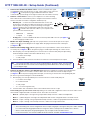
Figure 1. DTPTSW4HD4K Rear Panel
Installation Steps
1. Turn off and disconnect all of the equipment from the power source.
2. Mount the switcher on a rack shelf or furniture (optional).
3. Connect HDMI input sources to one or more of the DTPTSW4HD4K HDMI Inputs (see gure
1,
C
). The default
(Extron) EDID is present at each input and Hot
Plug
Detect (HPD) is actively controlled on each input.
NOTE: The default (Extron) EDID is 720p @ 60 Hz (see the
DTPTSW4HD4K User Guide for EDID table)
.
NOTE: LockIt
®
cable lacing brackets are provided to secure the HDMI cables to the rear panel connectors to reduce stress on
the HDMI connectors and prevent signal loss due to loose cable connections (see the LockIt Lacing Brackets on page 4).
4. Connect an RJ-45 output device to the DTP output (
E
) for either DTP or HDBT mode
(see image on right to wire the RJ-45 connector).
• If the receiving device is in the Extron DTP series, set the DTP/HDBT switch (
D
) DOWN to DTP.
• If the receiving device is HDBaseT enabled, set the DTP/HDBT switch UP to HDBT.
When the output is congured for DTP mode, remote power is available. When the output is
congured for HDBT mode, remote power is disabled and the switcher and receiver each
require its own 12 VDC power supply.
ATTENTION:
• Position this switch BEFORE connecting the appropriate device to the TP connector. Failure to
comply can damage the endpoint.
• Positionnez le sélecteur AVANT de connecter l’appareil approprié au connecteur TP.
Ne pas respecter cette procédure pourrait endommager le point de connexion.
• Do not connect these devices to a computer data or telecommunications network.
• Ne connectez pas cet appareil à un réseau de télécommunications ou de données informatiques.
A
Power inlet
B
Contact closure input and
Tally output ports
C
HDMI inputs
D
TP function switch
E
DTP Output RJ-45 port
F
Over TP RS-232 and IR port
G
Remote RS-232 port
H
Remote Auto port
Wire color
White-green
Green
White-orange
White-blue
Orange
White-brown
Brown
Blue
TIA/EIA T
568 B
TP Wires
12345678
Pins:
5
Pin
1
2
3
6
7
8
4
- - A MAX
POWER
12V
T
1
C T
2
C T
3
CG
4
C+VT
SIG LINK
OUT
1 2 3 4
RxTx
RS-232 IR
RxTxG
RxTx
RS-232 AUTO
G
CONTACT/TALLY
INPUTS
DTP T SW4 HD 4K
DTP
HDBT
REMOTE
OVER TP
G
5
C+VT G
6
C+VT
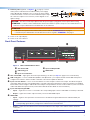
Extron
Cable Cubby
HDMI HDMIHDMI HDMI
HDMI
HDMI
HDMI
HDMI
Laptop
Laptop
Extron
Cable Cubby 700
Series/2 Cable
Access Enclosure
Extron
DTP T SW4
HD 4K
Transmitter
Flat Panel Display with HDBaseT
CATx Cable
up to 330'
(100 m)
1

5. Connect Over TP RS-232 and IR control. Connect a serial RS-232 signal,
a modulated IR signal, or both into this 3.5 mm, 5-pole captive screw connector
(see figure1,
F
, on the previous page) for bidirectional RS-232 and IR
communication (see the image on the right to wire the RS-232 and IR connector).
6. Connect control devices. Connect your computer to one of the following
DTPTSW4HD4K communication ports to congure and control the switcher
via SIS commands or Product Conguration Software (PCS):
• RS-232 port — Connect the unterminated transmit, receive, and
ground wires of the RS-232 cable to the three pins on the provided
3-pole captive screw plug, as shown in the image on the right.
Connect the plug to the rear panel Remote RS-232 connector (see
figure1,
G
), and the other end of the cable to your computer serial
port. Protocol for the RS-232 port:
• 9600 baud • 8 data bits
• 1 stop bit • no parity
• Config port — Connect a USB mini-B cable to the front panel USB connector (see figure2,
B
,
on the next page) for USB control.
7. Enable auto-input switching (optional). Use a jumper wire to connect the two pins of the 2-pole
captive screw plug (see the diagram to the right). Attach the plug to the Remote Auto switch port
(see figure1,
H
).
8. Connect Contact/Tally input sources (optional). Connect a push-button contact closure device to
a Contact port (see figure 1,
B
, on the previous page) to enable input switching via contact closure.
a. Wire and plug one of the provided 2-pole connectors into a Contact In/Tally Out port representing
the desired input number on the DTPTSW4HD4K (1, 2, or 3).
• C = Contact closure input
• T = Tally output
b. Press the button on the contact closure device to switch the connected input to the output.
TIP: The Contact and Tally connectors can be used with Extron “Show Me” cables. For each cable,
connect the red wire to the Contact Closure input pin (C)and the black wire to the ally Out pin (T)
(see the diagram right).
9. Connect an indicator device to the Tally Out port (optional). To identify the currently selected input when
the front panel buttons are not visible, connect a device such as an LED to the Contact In/Tally Out port
(see figure1,
B
on the previous page). When the input you are using is selected, the corresponding Tally Out
pin shorts to ground, activating the connected indicator.
a. Wire and plug one of the provided 4-pole connectors into the Contact In/Tally Out port.
• C = Contact closure input
• G = Contact Ground
• T = Tally output
• +V = +V connector (power wire)
b. Insert the LED+ wire of the button switch of the indicator device into the +V pin.
Contact/Tally ports operate in four modes depending on the needs and conguration of the user. These modes can be
selected and congured via SIS Commands or PCS
.
The modes are as follows:
• Mode 0 — (default) Inputs 1 through 4 are grouped and mutually exclusive; 5 and 6 are independent.
• Mode 1 — (advanced) Inputs 1 through 6 are independent and must be congured via SIS commands or PCS.
• Mode 2 — Inputs 1 through 4 are grouped and mutually exclusive; 5 and 6 are grouped and mutually exclusive.
• Mode 3 — Inputs 1 through 4 are mutually exclusive; 5 and 6 are in single switch mode.
NOTE:
• The Contact/Tally ports can be congured to select an input using inputs 1 through 4, with ports 5 and 6 available
for control and monitoring peripheral devices using a Pro Series control processor and GC Plus or GC Pro.
• When Contact/Tally inputs are grouped together, only one input can be selected at a time.
• For more information,
see the DTPTSW4HD4K User Guide, available at www.extron.com
.
T
CONTACT / TA LLY
C
G
CONTACT / TALLY
C+VT
Red
Black
Pigtail
“Show Me” Cable
Red
Black
Pigtail
“Show Me” Cable
T
CONTACT /
TALLY
1
CT
CG +VT
5
CONTACT /
TALLY
RxTx
IR
Device
Ground ( _ )
Receive (Rx)
Transmit (Tx)
Do not tin
the wires!
DTP T SW4 HD 4K
G
Ground
Receive pin
Transmit pin
Connected RS-232
and IR De
vice Pins
Receive pin
Transmit pin
RS-232
IR
Tx Rx Tx RxG
Tx/Rx
Pins
DTPTSW4HD4K • Setup Guide (Continued)
2

10. Connect power (optional, see figure1,
A
on page 1). Connect
an IEC power cord between the included 12 VDC power supply
and a 100-240 VAC, 50-60 Hz source. Connect the power supply
to either transmitter or receiver. Use the included tie-wrap to strap
the cord to the captive screw connector (see the diagram on the
right for wiring).
CAUTION: The wires must be kept separate while the power supply is plugged in. Remove power before wiring.
ATTENTION : Les deux cordons d’alimentation doivent être maintenus séparés lorsque la source d’alimentation est
branchée. Coupez l’alimentation avant d’effectuer un raccordement.
ATTENTION:
• Do not connect power to the switcher until you have read the ATTENTION notices on page4.
• Ne branchez pas l’alimentation au avant d’avoir lu les mises en garde « ATTENTION » aux page4.
11. Power on the output display.
12. Power on the source devices.
Front Panel Features
DTP T SW4 HD 4K
DTP HDMI SWITCHER
CONFIG
INPUTS
OUTPUT
1234
SIGNAL
HDCP
INPUTS
1 2 3 4
AUTO
SWITCH
AA
BB
CC
DD
EE
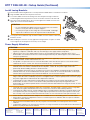
Figure 2. DTPTSW4HD4K Front Panel
A
Auto Switch LED
D
Input and Output LEDs
B
USB Config port
E
HDCP LEDs
C
Input selection buttons
A
Auto switch LED — Lights green when auto-input switching is in effect (see step7 on page2 for more information).
B
USB config port — Connect a USB cable (USB A to mini-B) between your computer and this female USB mini-B port to
congure and control the switcher via SIS commands or PCS and to update the rmware.
C
Inputs selection buttons — Press one of these buttons to select an input to switch to the output. The LED at the right of
each button lights when the corresponding input is selected. If auto-input switching is in effect, these buttons are disabled,
but the LEDs continue to light to indicate the selected input. The input buttons are also used to initiate a system reset and to
enable and disable front panel lockout (see the DTPTSW4HD4K User Guide for more information).
D
Inputs and Output Signal LEDs
• Inputs — Light when a source is connected to the corresponding input connector and TMDS clock activity is detected.
• Output — Lights when a video output is actively sent on the DTP/HDBT output.
E
HDCP LEDs
• Inputs — Light for each input if the connected sources are HDCP-encrypted and have been authenticated by the
switcher.
NOTE: If the source device connected to the selected input is HDCP encrypted (requires HDCP authentication), the
corresponding signal LED may not light unless HDCP has been authenticated.
• Output — Lights when the HDCP has been authenticated between the output of the switcher and the sink device
connected.
NOTE: HDCP is re-authenticated on the output whenever a new input is selected.
SECTION A–A
Ridges
Smooth
A
A
3/16"
(5 mm) Max.
POWER
12V
1.3A MAX
3

Extron Headquarters
+800.633.9876 Inside USA/Canada Only
Extron USA - West Extron USA - East
+1.714.491.1500 +1.919.850.1000
+1.714.491.1517 FAX +1.919.850.1001 FAX
Extron Europe
+800.3987.6673
Inside Europe Only
+31.33.453.4040
+31.33.453.4050 FAX
Extron Asia
+65.6383.4400
+65.6383.4664 FAX
Extron Japan
+81.3.3511.7655
+81.3.3511.7656 FAX
Extron China
+86.21.3760.1568
+86.21.3760.1566 FAX
Extron Middle East
+971.4.299.1800
+971.4.299.1880 FAX
Extron Australia
+61.8.8113.6800
+61.8.8351.2511 FAX
Extron India
1800.3070.3777
(Inside India Only)
+91.80.3055.3777
+91.80.3055.3737 FAX
© 2017 Extron Electronics All rights reserved. www.extron.com
DTPTSW4HD4K • Setup Guide (Continued)
LockIt Lacing Brackets
Use the included LockIt lacing brackets to securely fasten the HDMI cables to each device as follows.
1
Plug the HDMI cable into the rear panel connection.
2
Loosen the HDMI connection mounting screw from the panel enough to allow the
LockIt lacing bracket to be placed over it. The screw does not have to be removed.
3
Place the LockIt lacing bracket on the screw and against the HDMI connector, then
tighten the screw to secure the bracket.
ATTENTION:
• Do not overtighten the HDMI connection mounting screw. The shield it
fastens to is very thin and can easily be stripped.
• Ne serrez pas trop la vis de montage du connecteur HDMI. Le blindage
auquel elle est attachée est très n et peut facilement être dénudé.
4
Loosely place the included tie wrap around the HDMI connector and the LockIt lacing
bracket as shown.
5
While holding the connector securely against the lacing bracket, use pliers or similar
tools to tighten the tie wrap, then remove any excess length.
Power Supply Attentions
ATTENTION:
• Always use a power supply supplied and or specied by Extron. Use of an unauthorized power supply voids all
regulatory compliance certication and may cause damage to the supply and the end product.
• Utilisez toujours une source d’alimentation fournie ou recommandée par Extron. L’utilisation d’une source
d’alimentation non autorisée annule toute conformité réglementaire et peut endommager la source d’alimentation
ainsi que le produit nal.
• If not provided with a power supply, this product is intended to be supplied by a power source marked “Class 2” or
“LPS” and rated at 12 VDC and a minimum of 1.5 A.
• Si le produit n’est pas fourni avec une source d’alimentation, il doit être alimenté par une source d’alimentation
certié UL de classe 2 ou LPS, avec une tension nominale 12 Vcc, 1.5 A minimum.
• The installation must always be in accordance with the applicable provisions of National Electrical Code ANSI/
NFPA 70, article 725 and the Canadian Electrical Code part 1, section 16. The power supply shall not be
permanently xed to building structure or similar structure.
• Cette installation doit toujours être en accord avec les mesures qui s’applique au National Electrical Code ANSI/
NFPA70, article725, et au Canadian Electrical Code, partie1, section16. La source d’alimentation ne devra pas
être xée de façon permanente à une structure de bâtiment ou à une structure similaire.
• Power supply voltage polarity is critical. Incorrect voltage polarity can damage the power supply and the unit. The
ridges on the side of the cord identify the power cord negative lead. To verify the polarity before connection, plug in
the power supply with no load and check the output with a voltmeter.
• La polarité de la source d’alimentation est primordiale. Une polarité incorrecte pourrait endommager la source
d’alimentation et l’unité. Les stries sur le côté du cordon permettent de repérer le pôle négatif du cordon
d’alimentation. Pour vérier la polarité avant la connexion, brancher l’alimentation hors charge et mesurer sa sortie
avec un voltmètre.
• The length of the exposed (stripped) copper wires is important. The ideal length is 3/16inch (5mm). Longer bare
wires can short together. Shorter wires are not as secure in the connectors and could be pulled out.
• La longueur des câbles exposés est primordiale lorsque l’on entreprend de les dénuder. La longueur idéale est de
5mm (3/16inches). S’ils sont trop longs, les câbles exposés pourraient se toucher et provoquer un court circuit.
S’ils sont trop courts, ils peuvent être tirés facilement, même s’ils sont correctement serrés par les borniers à vis.
• Unless otherwise stated, the AC/DC adapters are not suitable for use in air handling spaces or in wall cavities.
• Sauf mention contraire, les adaptateurs CA/CC ne conviennent pas à une utilisation dans les espaces d’aération
ou dans les cavités murales.
• Remote power is intended for indoors use only. No part of a network that uses remote power can be routed
outdoors.
• L’alimentation à distance est exclusivement réservée à un usage en intérieur. Un réseau utilisant une alimentation à
distance ne peut pas être routé en extérieur.
3
1
2
3
4
5
68-2916-50 Rev. A
02 17
4
-
 1
1
-
 2
2
-
 3
3
-
 4
4


Extron DTP T SW4 HD 4K Manuel utilisateur
- Taper
- Manuel utilisateur
dans d''autres langues
- English: Extron DTP T SW4 HD 4K User manual
Documents connexes
-
Extron SW HD 4K Series Manuel utilisateur
-
Extron DTP2 T 203 Manuel utilisateur
-
-
-
-
Extron DA2 HD 4K PLUS Manuel utilisateur
-
Extron DTP T FB 332 Manuel utilisateur
-
-
-
Extron PC 101 Manuel utilisateur