Kichler Lighting 43691NI Manuel utilisateur
- Taper
- Manuel utilisateur

Date Issued: 10/03/17
IS-43693-CB
We’re here to help 866-558-5706
Hrs: M-F 9am to 5pm EST
CAUTION – RISK OF SHOCK –
Disconnect Power at the main circuit breaker panel or main
fusebox before starting and during the installation.
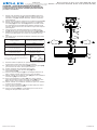
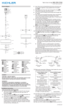
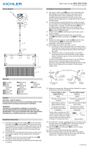
1) Pass xture wire from coupling[1] on top of xture through end
of stem[2]. (Be sure the stem has a short threaded tube[3] on
each end.) Thread the stem into the coupling.
2) Pass top of stem through hole in canopy[4].
3) Pass xture wire through a lockwasher[5] followed by a hex-
nut[6]. Slip the lockwasher onto threaded pipe protruding from
inside canopy. Thread hexnut onto end of threaded pipe.
Tighten to secure.
4) Find the appropriate threaded holes on mounting strap[7].
Assemble mounting screws[8] into threaded holes.
5) Attach mounting strap to outlet box[9]. Mounting strap can be
adjusted to suit position of xture.
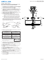
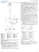
6) Grounding instructions: (See Illus. A or B).
A) On xtures where mounting strap is provided with a
hole and two raised dimples. Wrap ground wire from
outlet box around green ground screw, and thread into
hole.
B) On xtures where a cupped washer is provided. Attach
ground wire from outlet box under cupped washer and
green ground screw, and thread into mounting strap.
If xture is provided with ground wire. Connect xture ground
wire to outlet box ground wire with wire connector. (Not provid-
ed.) After following the above steps. Never connect ground wire
to black or white power supply wires.
7) Make wire connections. Reference chart below for correct con-
nections and wire accordingly.
8) Push xture to ceiling, carefully passing mounting screws
through holes in canopy. NOTE: Be certain wires do not get
pinched between canopy and ceiling.
9) Use lock-up knobs[10] and lockwashers[11] to secure canopy.
Tighten to secure.
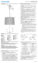
10) Insert recommended bulb(s) (not supplied).
11) Thread the short end of the threaded pipe[12] into the cou-
pler[13].
12) Thread a hexnut[6] on the bottom threads of the pipe.
(Leave about 3/4” threads exposed ).
13) Slip a steel washer[15] followed by a rubber washer[16] onto the
threaded pipe.
14) Carefully rest the shade[17] onto the glass. Raise up to the
xture and slip the hole of the glass[18] over the threaded pipe.
Rest the glass against the rubber washer.
15) Slip a rubber washer followed by a steel washer onto the
threaded pipe.
16) Thread a hexnut[19] onto the threaded pipe to secure the glass.
Do not over-tighten.
17) Thread the nial[20] onto the threaded pipe to cover the hexnut.
Do not over-tighten.
GREEN GROUND
SCREW
CUPPED
WASHER
OUTLET BOX
GROUND
FIXTURE
GROUND
DIMPLES
WIRE CONNECTOR
OUTLET BOX
GROUND
GREEN GROUND
SCREW
FIXTURE
GROUND
A
B
Connect Black or
Red Supply Wire to:
Connect
White Supply Wire to:
Black White
*Parallel cord (round & smooth) *Parallel cord (square & ridged)
Clear, Brown, Gold or Black
without tracer
Clear, Brown, Gold or Black
with tracer
Insulated wire (other than green)
with copper conductor
Insulated wire (other than green)
with silver conductor
*Note: When parallel wires (SPT I & SPT II)
are used. The neutral wire is square shaped
or ridged and the other wire will be round in
shape or smooth (see illus.)
Neutral Wire
8
7
9
10
11
13
12
15
16
16
15
19
20
17
18
5
6
3
2
1
4
6

Date Issued: 10/03/17
IS-43693-CB
INSTRUCTIONS
For Assembling and Installing Fixtures in Canada
Pour L’assemblage et L’installation Au Canada
Nous sommes là pour vous aider 866-558-5706
Heures : du lundi au vendredi, de 9h à 17h (heure de l’Est)
ATTENTION – RISQUE DE DÉCHARGES ÉLECTRIQUES -
Couper le courant au niveau du panneau du disjoncteur du
circuit principal ou de la boîte à fusibles principale avant de
procéder à l’installation.
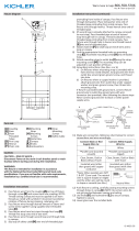
1) Passer le l de xation de l’accouplement [1] au-dessus du
luminaire à travers la tige [2]. (Assurez-vous que la tige a un
tube leté court [3] à chaque extrémité). Enlez la tige dans
l’accouplement.
2) Passez le haut de la tige à travers le trou dans la canopée [4].
3) Passer le l de xation à travers le trou dans la rondelle de
verrouillage[5] suivi d’un hexain[6]. Enler la rondelle d’arrêt
sur l’extrémité du tuyau leté faisant saillie à l’intérieur de la
canopée. Enlez hexnut sur l’extrémité du tuyau leté. Apriete
para asegurar.
4) Trouvez les trous taraudés appropriés sur sangle de xa-
tion[7]. Monter les vis de montage dans les trous letés[8].
5) Attachez la sangle de xation à la boîte de sortie[9]. Sangle de
xation peut être ajustée en fonction de la position de mon-
tage.
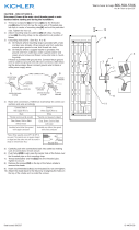
6) Connecter les ls. Se porter au tableau ci-dessous pour faire
les connexions.
7) Poussez xation au plafond, en passant soigneusement les vis
de montage à travers des trous dans la canopée.
8) Utilisez les boutons de verrouillage[10] et les lave-glaces[11]
pour sécuriser la voilure. Serrez pour sécuriser.
9) Insérez l’ampoule recommandée. (Non fourni)
10) Visser l’extrémité courte du tube leté [12] dans
l’accouplement [13].
11) Visser un écrou hexagonal [6] sur les letages inférieurs du
tube. (Laisser exposer environ 3/4 po (2 cm) des lets).
12) Glisser d’abord une rondelle en acier [15] puis une rondelle en
caoutchouc [16] sur le tube leté.
13) Poser soigneusement le cache [17] sur le verre. Relever
jusqu’au luminaire et passer le trou du verre [18] sur le tube
leté. Poser le verre contre la rondelle en caoutchouc.
14) Glisser d’abord une rondelle en caoutchouc puis une rondelle
en acier sur le tube leté.
15) Visser un écrou hexagonal [19] sur le tube leté pour xer le
verre. Ne pas serrer avec excès.
16) Visser l’ornement [20] sur le tube leté pour couvrir l’écrou
hexagonal. Ne pas serrer avec excès.
Connecter le fil noir ou
rouge de la boite
Connecter le fil blanc de la boîte
A Noir A Blanc
*Au cordon parallèle (rond et lisse)
*Au cordon parallele (à angles droits el strié)
Au bransparent, doré, marron, ou
noir sans fil distinctif
Au transparent, doré, marron, ou
noir avec un til distinctif
Fil isolé (sauf fil vert) avec
conducteur en cuivre
Fil isolé (sauf fil vert) avec
conducteur en argent
*Remarque: Avec emploi d’un fil paralléle
(SPT I et SPT II). Le fil neutre est á angles
droits ou strié et l’autre fil doit étre rond ou
lisse (Voir le schéma).
Fil Neutre
8
7
9
10
11
13
12
15
16
16
15
19
20
17
18
5
6
3
2
1
4
6
-
 1
1
-
 2
2


Kichler Lighting 43691NI Manuel utilisateur
- Taper
- Manuel utilisateur
dans d''autres langues
- English: Kichler Lighting 43691NI User manual
Documents connexes
-
 Kichler Lighting 44313PN Manuel utilisateur
-
Kichler 43694CH Manuel utilisateur
-
-
 Kichler Lighting 44251NI Manuel utilisateur
-
 Kichler Lighting 44332DBK Manuel utilisateur
-
 Kichler Lighting 44167BK Manuel utilisateur
-
Kichler Lighting 43596BK Manuel utilisateur
-
 Kichler Lighting 52016CLP Manuel utilisateur
-
 Kichler Lighting 44079BK Manuel utilisateur


