Kichler Lighting 44313PN Manuel utilisateur
- Taper
- Manuel utilisateur

IS-44313-CB
We’re here to help 866-558-5706
Hrs: M-F 9am to 5pm EST
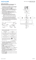
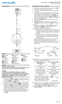
4) Pass xture wire through desired amount of stems and
screw stems together using supplied short threaded
tubes[C].
5) Pass xture wire from last stem through rst loop[D].
Thread rst loop onto end of last stem.
6) Pass xture wire through second loop and through hole
in canopy.
7) Pass xture wire through lockwasher. Place lockwasher
onto end of threaded pipe protruding from inside
canopy. Pass xture wire through hexnut. Thread hexnut
onto end of threaded pipe.
8) (If second loop is already aached to canopy, proceed
to next step). Pass threaded pipe at end of second loop
through hole in canopy. Thread lockwasher[L] onto
threaded pipe protruding from inside canopy. Pass
xture wire through hole in hexnut and thread hexnut
[E]onto end of threaded pipe.
9) Aach open chain link[F] to small loop at end of each
stem and to each loop on canopy and close the open
chain link by placing a piece of cloth over the open link
and using a pair of pliers gently squeeze the link closed.
10) Find the appropriate threaded holes on mounng
strap[G]. Assemble mounng screws[H] into threaded
holes.
11) Aach mounng strap to outlet box[I] using the strap
mounng screws[M]. The mounng strap can be
adjusted to suit posion of xture.
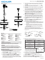
12) Grounding instrucons: (See Illus. a or b).
a) On xtures where mounng strap is provided with a
hole and two raised dimples, wrap ground wire from
outlet box around green ground screw, and thread
into hole.
b) On xtures where a cupped washer is provided,
aach ground wire from outlet box under cupped
washer and green ground screw, then thread into
mounng strap.
If xture is provided with ground wire, connect xture
ground wire to outlet box ground wire with wire
connector (not provided.) aer following the above steps.
Never connect ground wire to black or white power
supply wires.
13) Make wire connecon. Reference chart below for correct
connecons and wire accordingly.
Connect Black or Red
Supply Wire to:
Connect White Supply
Wire to:
Black White
*Parallel cord (round &
smooth)
*Parallel cord (square &
ridged)
Clear, Brown, Gold or
Black without Tracer
Clear, Brown, Gold or Black
with Tracer
Insulated wire (other
than green) with copper
conductor
Insulated wire (other
than green) with silver
conductor
*Note: When parallel wire (SPT
1 & SPT 2) are used. The neutral
wire is square shaped or ridged
and the other wire will be round
in shape or smooth (see illus.)
Neutral Wire
14) Push xture to ceiling, carefully passing mounng screws
through holes in canopy[J]. NOTE: Be certain wires do
not get pinched between canopy and ceiling.
15) Use knobs[K] and lockwashers[L] to secure canopy.
Tighten to secure.
16) Rotate the xture arms[W] into the correct posion.
17) Insert recommended bulb(s). (Not supplied)
18) Take one of the rubber washers[S] and slide up onto the
GREEN GROUND
SCREW
CUPPED
WASHER
OUTLET BOX
GROUND
FIXTURE
GROUND
DIMPLES
WIRE CONNECTOR
OUTLET BOX
GROUND
GREEN GROUND
SCREW
FIXTURE
GROUND
a
b
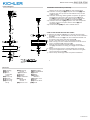
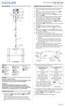
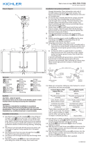
Fixture Diagram
Parts List
Cauons
CAUTION – RISK OF SHOCK –
Disconnect Power at the main circuit breaker panel or main
fusebox before starng and during the installaon.
WARNING:
This xture is intended for installaon in accordance
with the Naonal Electrical Code (NEC) and all local code
specicaons. If you are not familiar with code requirements,
installaon by a cered electrician is recommended.
Installaon Instrucons
[A] Coupling
[B] Stem
[C] Short
Threaded
Tubes
[D] First Loop
[E] Hexnut
[F] Chain Link
[G] Mounting
Strap
[H] Mounting
Screws
[I] Outlet Box
[J] Canopy
[K] Knobs
[L] Lockwashers
[M] Strap
Mounting
Screws
[N] Center Trim
[O] Main Body
[P] Threaded Rod
[Q] Shade
[R] Glass
[S] Rubber
Washers
[T] Small Trim
[U] Trim
[V] Fixture Arms
[W] Finial
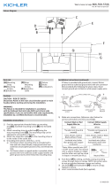
HANG MOUNTING INSTRUCTIONS:
1) Take the threaded rod[P]and run the SPT wire through
the center of rod and thread into the top center of
xture body[O].
2) Place the center trim[N] over the installed threaded rod
and secure into place with the coupler[A].
3) Pass xture wire from the coupling[A] on top of xture
through a stem[B] and short threaded tubes[C]
and screw stem into coupling. NOTE: Thread locking
compound must be applied to all stem threads as noted
with symbol (4) to prevent accidental rotaon of xture
during cleaning, relamping, etc.
F
G
E
D
H
A
B
K
J
I
M
►
►
C
N
L
►
P
N
O
Q
R
S
T
U
V
W
X
Y
Z
S
C
C

IS-44313-CB
We’re here to help 866-558-5706
Hrs: M-F 9am to 5pm EST
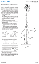
boom of the main body[O] over the treaded pipe.
19) Take the circular glass[R] and place the shade[Q] onto
the glass and raise up over the threaded rod up to the
rubber gasket.
20) Take the remaining rubber gasket and place up against
the boom of the glass, take the small trim[T] and
trim[U] and slide up to the rubber washer and secure
into place with the hexnut[E] and lockwasher[L].
21) Take the xture arms[V] and place over the trim pieces
as shown. Secure into place with a hexnut[E] and
lockwasher[L].
22) Install the nial[W] over the installed hexnut.
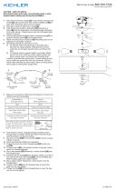
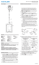
SEMI-FLUSH MOUNTING INSTRUCTIONS:
1) Take the threaded rod[P]and run the SPT wire through
the center of rod and thread into the top center of xture
body[O].
2) Place the center trim[N] over the installed threaded rod
and secure into place with the coupler[A].
3) Install a threaded tube into the installed coupler.
4) Slide canopy over the installed threaded rod and secure
using a lockwasher[L] and hexnut[E].
5) Find the appropriate threaded holes on mounng
strap[G]. Assemble mounng screws[J] into threaded
holes.
6) Aach mounng strap to outlet box[I]. The mounng
strap can badjusted to suit posion of xture using the
strap mounng screws[M].
7) Follow steps 13 though 22 to complete installaon.
Installaon Instrucons (connued)
F
G
E
D
H
A
B
K
J
I
M
►
►
C
N
L
►
P
N
O
Q
R
S
T
U
V
W
X
Y
Z
S
C
C
Fixture Diagram
Parts List
[A] Coupling
[B] Stem
[C] Short
Threaded
Tubes
[D] First Loop
[E] Hexnut
[F] Chain Link
[G] Mounting
Strap
[H] Mounting
Screws
[I] Outlet Box
[J] Canopy
[K] Knobs
[L] Lockwashers
[M] Strap
Mounting
Screws
[N] Center Trim
[O] Main Body
[P] Threaded Rod
[Q] Shade
[R] Glass
[S] Rubber
Washers
[T] Smaller Trim
[U] Trim
[V] Fixture Arms
[W] Finial

IS-44313-CB
Nous sommes là pour vous aider 866-558-5706
Heures : du lundi au vendredi, de 9h à 17h (heure de l’Est)
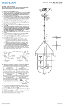
INSTRUCTIONS:
For Assembling and Installing Fixtures in Canada
Pour L’assemblage et L’installaon Au Canada
1) Prenez la ge letée [P] et faites passer le l du SPT à
travers le centre de la ge et enlez-le dans le centre
supérieur du corps du luminaire [O].
2) Placez la garniture centrale [N] sur la ge letée installée
et xez-la en place avec le coupleur [L].
3) Passer le l de xaon de l’accouplement [A] sur le
dessus du luminaire à travers une ge [B] et des tubes
letés et visser la ge dans le raccord. REMARQUE: le
composé de verrouillage de letage doit être appliqué à
tous les ls de la ge comme indiqué avec un symbole(4)
éché pour empêcher la rotaon accidentelle du
luminaire pendant le neoyage, la relamping, etc..
4) Passer le l de xaon à travers la quanté souhaitée de
ges et la visdérive en ulisant des tubes à letage court
fournis[C].
5) Passer le l de xaon de la dernière ge à la première
boucle[D]. Enlez la première boucle sur la n de la
dernière ge.
6) Passer le l de xaon à travers la deuxième boucle et le
trou traversant dans la canopée.
7) Passer le l du luminaire à travers la rondelle-frein.
Placez la rondelle-frein sur l’extrémité du tuyau leté
dépassant de l’intérieur de la capote. Passer le l du
luminaire à travers un écrou hexagonal. Enler le boulon
à tête hexagonale sur l’extrémité du tuyau leté.
8) (Si la seconde boucle est déjà aachée à la canopée,
passez à l’étape suivante). Passer le tuyau leté[L]
à la n du deuxième trou traversant dans le capot.
Enler le disposif de verrouillage sur le tuyau leté en
saillie à parr de la canopée intérieure. Passer le l de
xaon dans le trou dans l’écrou hexagonal[E] et enler
l’hexagone sur l’extrémité du tuyau leté.
9) Aachez le maillon de chaîne[F] à la pete boucle à la
n de la ge et faites une boucle sur la canopée.
10) Trouvez les trous taraudés appropriés sur sangle de
xaon[G]. Monter les vis de montage [H] dans les trous
letés.
11) Aachez la sangle de xaon à la boîte de sore[I] à
l’aide des vis de xaon de la courroie[M]. sangle de
xaon peut être ajustée en foncon de la posion de
montage.
12) Connecter les ls. Se reporter au tableau ci-dessous pour
faire les connexions.
Connecter le l noir ou
rouge de la boite
Connecter le l blanc de
la boîte
A Noir A Blanc
*Au cordon parallèle (rond
et lisse)
*Au cordon parallèle (à
angles droits el strié)
Au transparent, doré,
marron, ou noir sans l
disncf
Au transparent, doré,
marron, ou noir avec un l
disncf
Fil isolé (sauf l vert) avec
conducteur en cuivre
Fil isolé (sauf l vert) avec
conducteur en argent
*Remarque: Avec emploi d’un
l paralléle (SPT 1 et SPT 2). Le
l neutre est á angles droits ou
strié et l’autre l doit étre rond
ou lisse (Voir le schéma).
Fil Neutre
13) Poussez xaon au plafond, en passant soigneusement
les vis de montage à travers des trous dans la
canopée[J].REMARQUE : Vous assurer que tous les ls
sont dans le couvercle et ne se retrouvent pas pincés
entre le couvercle et le plafond.
14) Ulisez les boutons[K] et les systèmes de verrouillage[L]
pour sécuriser le voile. Serrez pour sécuriser.
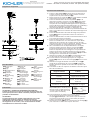
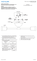
Diagramme d’appareils
ATTENTION – RISQUE DE DÉCHARGES ÉLECTRIQUES -
Couper le courant au niveau du panneau du disjoncteur du
circuit principal ou de la boîte à fusibles principale avant de
procéder à l’installaon.
ATTENTION:
Ce luminaire doit être installé conformément aux codes
d’électricité naonaux (NEC) et sasfaire toutes les
spécicaons des codes locaux. Si vous ne connaissez pas
les exigences de ces codes, il est recommandé de coner
l’installaon à un électricien ceré.
Liste des Pièces
Précauons
[A] L’accouple-
ment
[B] Tige
[C] Filetage Court
Fournis
[D] Première
Boucle
[E] Ecrou hexag-
onal
[F] Maillon de
Chaîne
[G] Sangle de
Fixation
[H] Vis de
Montage
[I] Boîte de
Sortie
[J] Canopée
[K] Boutons
[L] Systèmes de
Verrouillage
[M] Vis de xaon
de la courroie
[N] La garniture
centrale
[O] Du corps
principal
[P] La ge letée
[Q] Le store
[R] Le verre circu-
laire
[S] Des rondelles
en caou-
tchouc
[T] La pet garni-
ture
[U] La garniture
[V] Le boulon à
tête hexago-
nale
[W] Les bras de
xaon
Instrucons d’installaon
F
G
E
D
H
A
B
K
J
I
M
►
►
C
N
L
►
P
N
O
Q
R
S
T
U
V
W
X
Y
Z
S
C
C

IS-44313-CB
Nous sommes là pour vous aider 866-558-5706
Heures : du lundi au vendredi, de 9h à 17h (heure de l’Est)
INSTRUCTIONS:
For Assembling and Installing Fixtures in Canada
Pour L’assemblage et L’installaon Au Canada
15) Tournez les bras de xaon [W] dans la bonne posion.
16) Insérer les ampoules recommandées. (Non fourni)
17) Prenez une des rondelles en caoutchouc [S] et glissez-la sur
le bas du corps principal [O] par-dessus le tuyau à gorges.
18) Prenez le verre circulaire [R] et placez le store [Q] sur le
verre et soulevez-le par-dessus la ge letée jusqu’au joint
en caoutchouc.
19) Prenez le joint en caoutchouc restant et placez-le contre le
fond de la vitre, prenez la pet garniture [T] et la garniture
[U] et glissez jusqu’à la rondelle en caoutchouc et xez-la
en place avec le boulon à tête hexagonale.
20) Prenez les bras de xaon [V] et placez-les sur les
garnitures comme indiqué. Fixer en place avec un écrou
hexagonal [E] et une rondelle d’arrêt.
21) Installez le faîteau [W] sur l’hexagone installé.
Instrucons d’installaon (a connué)
F
G
E
D
H
A
B
K
J
I
M
►
►
C
N
L
►
P
N
O
Q
R
S
T
U
V
W
X
Y
Z
S
C
C
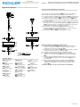
Diagramme d’appareils
INSTRUCTIONS DE MONTAGE SEMI-FLUSH:
1) Prenez la ge letée [P] et faites passer le l du SPT à
travers le centre de la ge et enlez-le dans le centre
supérieur du corps du luminaire [O].
2) Placez la garniture centrale [N] sur la ge letée installée
et xez-la en place avec le coupleur [L].
3) Installez un tube leté dans le coupleur installé.
4) Glissez le capot sur la ge letée installée et xez-la à
l’aide d’une rondelle-frein [C] et d’un écrou hexagonal
[K].
5) Trouvez les trous letés appropriés sur la courroie de
montage [G]. Assemblez les vis de xaon [J] dans les
trous letés.
6) Fixez la sangle de xaon à la boîte de sore [F]. La
sangle de montage peut êtreajusté en foncon de la
posion de l’appareil à l’aide des vis de xaon de la
sangle [E].
Suivez les étapes 13 à 21 pour terminer l’installaon.
[A] L’accouple-
ment
[B] Tige
[C] Filetage Court
Fournis
[D] Première
Boucle
[E] Ecrou hexag-
onal
[F] Maillon de
Chaîne
[G] Sangle de
Fixation
[H] Vis de
Montage
[I] Boîte de
Sortie
[J] Canopée
[K] Boutons
[L] Systèmes de
Verrouillage
[M] Vis de xaon
de la courroie
[N] La garniture
centrale
[O] Du corps
principal
[P] La ge letée
[Q] Le store
[R] Le verre circu-
laire
[S] Des rondelles
en caou-
tchouc
[T] La pet garni-
ture
[U] La garniture
[V] Les bras de
xaon
[W] Le faîteau
Liste des Pièces
-
 1
1
-
 2
2
-
 3
3
-
 4
4


Kichler Lighting 44313PN Manuel utilisateur
- Taper
- Manuel utilisateur
dans d''autres langues
- English: Kichler Lighting 44313PN User manual
Documents connexes
-
 Kichler Lighting 44291WWW Manuel utilisateur
-
 Kichler Lighting 43691NI Manuel utilisateur
-
 Kichler Lighting 43692NI Manuel utilisateur
-
 Kichler Lighting 43195BK Manuel utilisateur
-
 Kichler Lighting 43642BK Manuel utilisateur
-
 Kichler Lighting 44293WWW Manuel utilisateur
-
 Kichler Lighting 44115PN Manuel utilisateur
-
 Kichler Lighting 44116PN Manuel utilisateur
-
 Kichler Lighting 44044AUB Manuel utilisateur
-
 Kichler Lighting 44045AUB Manuel utilisateur


