Kichler Lighting 44293WWW Manuel utilisateur
- Taper
- Manuel utilisateur

IS-44293-CB
We’re here to help 866-558-5706
Hrs: M-F 9am to 5pm EST
If xture is provided with ground wire, connect xture
ground wire to outlet box ground wire with wire connector
(Not provided) aer following the above steps. Never
connect ground wire to black or white power supply wires.
5) Make wire connecons. Reference chart below for
correct connecons and wire accordingly.
Connect Black or Red
Supply Wire to:
Connect White Supply
Wire to:
Black White
*Parallel cord (round &
smooth)
*Parallel cord (square &
ridged)
Clear, Brown, Gold or
Black without Tracer
Clear, Brown, Gold or Black
with Tracer
Insulated wire (other
than green) with copper
conductor
Insulated wire (other
than green) with silver
conductor
*Note: When parallel wire (SPT
1 & SPT 2) are used. The neutral
wire is square shaped or ridged
and the other wire will be round
in shape or smooth (See illus.)
Neutral Wire
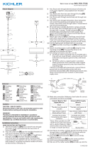
6) Push xture[F] to ceiling, carefully passing mounng
screws through holes in canopy. NOTE: Be certain wires
do not get pinched between canopy and ceiling.
7) Use knobs[G] and lockwashers[H] to secure canopy.
Tighten to secure.
8) Insert recommended bulb (Not supplied).
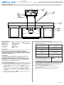
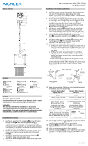
GREEN GROUND
SCREW
CUPPED
WASHER
OUTLET BOX
GROUND
FIXTURE
GROUND
DIMPLES
WIRE CONNECTOR
OUTLET BOX
GROUND
GREEN GROUND
SCREW
FIXTURE
GROUND
a
b
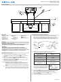
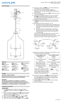
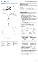
Fixture Diagram
Parts List
Cauons
CAUTION – RISK OF SHOCK –
Disconnect Power at the main circuit breaker panel or main
fusebox before starng and during the installaon.
WARNING:
This xture is intended for installaon in accordance
with the Naonal Electrical Code (NEC) and all local code
specicaons. If you are not familiar with code requirements,
installaon by a cered electrician is recommended.
Installaon Instrucons (connued)
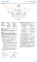
Installaon Instrucons
F
E
G
H
C
A
D
B
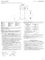
1) Find the appropriate threaded holes on mounng
strap[A]. Assemble mounng screws[B] into threaded
holes.
2) Aach mounng strap to outlet box[C] using the
strap mounng screws[D]. The mounng strap can be
adjusted to suit posion of xture.
3) Aach the inspecon cable[E] to the mounng strap or
to the inside of the outlet box.
4) Grounding instrucons: (See Illus. a or b).
a) On xtures where mounng strap is provided with a
hole and two raised dimples, wrap ground wire from
outlet box around green ground screw, and thread into
hole.
b) On xtures where a cupped washer is provided, aach
ground wire from outlet box under cupped washer and
green ground screw, then thread into mounng strap.
[A] Mounting
Strap
[B] Mounting
Screws
[C] Outlet Box
[D] Strap
Mounting
Screws
[E] Inspection
Cable
[F] Fixture
[G] Knobs
[H] Lockwashers

IS-44293-CB
Nous sommes là pour vous aider 866-558-5706
Heures : du lundi au vendredi, de 9h à 17h (heure de l’Est)
INSTRUCTIONS:
For Assembling and Installing Fixtures in Canada
Pour L’assemblage et L’installaon Au Canada
4) Connecter les ls. Se reporter au tableau ci-dessous pour
faire les connexions.
Connecter le l noir ou
rouge de la boite
Connecter le l blanc de
la boîte
A Noir A Blanc
*Au cordon parallèle (rond
et lisse)
*Au cordon parallèle (à
angles droits el strié)
Au transparent, doré,
marron, ou noir sans l
disncf
Au transparent, doré,
marron, ou noir avec un l
disncf
Fil isolé (sauf l vert) avec
conducteur en cuivre
Fil isolé (sauf l vert) avec
conducteur en argent
*Remarque: Avec emploi d’un
l paralléle (SPT 1 et SPT 2). Le
l neutre est á angles droits ou
strié et l’autre l doit étre rond
ou lisse (Voir le schéma).
Fil Neutre
5) Enfoncez le luminaire[F] sur le plafond, en passant
soigneusement les vis de xaon dans les trous dans le
voile. REMARQUE: Soyez certain que les ls ne sont pas
pincés entre le dos et le plafond.
6) Uliser les boutons[G] et les disposifs de
verrouillage[H] pour sécuriser la voûte. Serrez pour
sécuriser.
7) Installer la ou les ampoules recommandées (Non
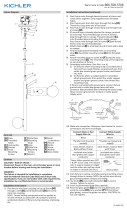
Diagramme d’appareils
ATTENTION – RISQUE DE DÉCHARGES ÉLECTRIQUES -
Couper le courant au niveau du panneau du disjoncteur du
circuit principal ou de la boîte à fusibles principale avant de
procéder à l’installaon.
ATTENTION:
Ce luminaire doit être installé conformément aux codes
d’électricité naonaux (NEC) et sasfaire toutes les
spécicaons des codes locaux. Si vous ne connaissez pas
les exigences de ces codes, il est recommandé de coner
l’installaon à un électricien ceré.
Liste des Pièces
Précauons
[A] Barrette de
Montage
[B] Vis de
Montage
[C] Boîte de
Sortie
[D] Vis de Fixation
de la Courroie
[E] Inspection
Cable
[F] Luminaire
[G] Boutons
[H] Dispositifs de
Verrouillage
Instrucons d’installaon
F
E
G
H
C
A
D
B
1) Trouver les trous letés appropriés sur la barree de
montage[A]. Vissez les vis de montage[B] dans les trous
letés.
2) Fixez la courroie de montage à la boîte de sore[C] à
l’aide des vis de xaon de la courroie[D]. La sangle de
montage peut être ajustée en foncon de la posion du
luminaire.
3) Fixez le câble d’inspecon [E] à la sangle de xaon ou à
l’intérieur de la boîte de sore.
Instrucons d’installaon (a connué)
-
 1
1
-
 2
2


Kichler Lighting 44293WWW Manuel utilisateur
- Taper
- Manuel utilisateur
dans d''autres langues
Documents connexes
-
 Kichler Lighting 44224BK Manuel utilisateur
-
Kichler 43694CH Manuel utilisateur
-
 Kichler Lighting 44313PN Manuel utilisateur
-
 Kichler Lighting 44291WWW Manuel utilisateur
-
 Kichler Lighting 42498NI Manuel utilisateur
-
 Kichler Lighting 44379BK Manuel utilisateur
-
 Kichler Lighting 44297WWW Manuel utilisateur
-
 Kichler Lighting 44299WWW Manuel utilisateur
-
Kichler Lighting 44169BK Manuel utilisateur
-
 Kichler Lighting 44335DBK Manuel utilisateur


