La page est en cours de chargement...

Instruction Manual
Manuel d’instruction • Manual de instrucción
B
ilge
P
ro
™
1600
B
ilge
P
ro
™
2200
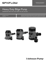
High-performance, heavy-duty
submersible bilge pumps
BilgePumpMan_1600-2200.indd 1 2/15/06 12:40:40 PM

4
ENGLISH
Security
• The pump may not be used for liquids other than water/bilge water.
• Always install the pump according to the wiring diagram, see pages 10-11.
• Always use the fuse required, see “Specifications” below.
• The wire connections must be sealed with a marine sealant.
• Insulation or cable sheathings must be placed above the highest bilge water level.
• Do not run dry.
Installation
Please follow the installation instructions carefully to assure maximum efficiency in your bilge
pump operation.
1. Remove the strainer from the bottom of the pump by depressing the lock tabs on both sides
of the pump.
2. Determine the desired location for the pump. Usually it is placed in the lowest point of the bilge.
3. Position the strainer so that the pump nozzle is in the proper position to connect to the discharge hose.
4. Mount the strainer. If attaching the strainer to wood, fasten with stainless steel screws. If attaching
the strainer to metal or fiberglass, first mount a wooden block and then fasten the strainer to the
wooden block.
5. Mount the pump on the strainer so that both locktabs “snap” into place.
6. The pump is now equipped with 1-1/8" (29mm) or 1-1/4" (32mm) barbed ports. The port threads into
the discharge area of the pump. To install the check valve, place stainless steel washer into the dis-
charge area of pump. Next place the Nitrile flapper over the washer. Then thread on port [1-1/8" (29mm)
barbed or 1-1/4" (32mm) barbed] on to pump’s discharge. Tighten port until port is bottomed out with
pump body. NOTE: The check valve supplied with your pump is used to prevent the backflow of water.
The utilization of the check valve requires you to be mindful of its functionality. The check valve material
is made of Nitrile material to be used for water applications only. Also, the check valve will reduce the
flow of the pump. The purpose of the check valve is to minimize back flow of water, however, over time
water will seep back into the hull when the pump is not running. If flow is critical to the application
Specifications
1600 2200
Hose size 1-1/8" (29mm) or 1-1/4" (32mm) 1-1/8" (29mm) or 1-1/4" (32mm)
Capacity, straight (13.6V) 1600 gph (6055 Lph) 2200 gph (8328 Lph)
Capacity, 1m head (13.6V) 1450 gph (5490 Lph) 1800 gph (6810 Lph)
Voltage 12V DC 12V DC
Amperage 7A 7.5A
Fuse size 10A 12A
Body Thermoplastic Thermoplastic
Shaft SS2343/AISI 316 Stainless Steel SS2343/AISI 316 Stainless Steel
Shaft seal Lip seal Mechanical seal, carbon/ceramic
Wire size 16 GA (1.5mm) 16 GA (1.5mm)
Max height 6" (152mm) 7" (177mm)
Max dia. 4-1/4" (108mm) 4-1/4" (108mm)
Weight 2.9 lb (1.3 kg) 5 lb (2.3 kg)
Model 7923642 BilgePro
™
1600
Model 7923659 BilgePro
™
2200
12V submersible bilge pump for pumping bilge water in marine environment. To be installed in the keelson.
BilgePumpMan_1600-2200.indd 4 2/15/06 12:40:41 PM

5
Maintenance
Regularly check the pump to be sure that the filter base and impeller are not clogged with debris. To clean,
push in the tabs and lift up the pump housing. Note! The discharge hose need not be removed.
Accessories (Always install according to the wiring diagram on pages 10-11.)
Model 543546 BilgePro Auto 3-Way Panel Switch
Model 7865637 BilgePro Auto Water Sensing Switch
Model 543561 BilgePro Auto Float Switch
ENGLISH
of the pump, it is recommended that the check valve not be used. Also, when winterizing your boat,
remove the check valve to avoid ice formation and/or degradation of the check valve.
7. Select a point where the bilge water is to be pumped overboard as high as possible above the water line
and at the shortest distance from the pump. Install a 1-1/8" (29mm) or 1-1/4" (32mm) thru-hull fitting.
8. Fasten a 1-1/8" (29mm) or 1-1/4" (32mm) fuel-resistant hose from the pump outlet to the thru-hull fit
-
ting. Avoid sharp bends or loops. Support the hose if necessary. Note: In order to prevent air locks it is
important that the hose not be allowed to dip below the pump outlet. The hose should be
constantly rising.
9. Connect the brown wire to the positive (+) terminal of the battery, and the black wire to the negative (-)
terminal of the battery. See wiring diagram, pages 10-11.
10. Important: All electrical wiring must be clamped with the connections well above the bilge water level.
Do not remove the insulation more than necessary. All wiring connections should be sealed with a
marine sealant to avoid oxidation.
There’s nothing more important to us than customer satisfaction.
If you have any questions or your purchase does not meet your
expectations, please do one of the following:
• Contact your local West Marine store
• Call
1-800-BOATING
• Contact us at
www.westmarine.com
BilgePumpMan_1600-2200.indd 5 2/15/06 12:40:42 PM

7
Nettoyage
Vérifier régulièrement si le filtre et la turbine sont encrassés. Pour nettoyer, enfoncer les verrous et
soulever le corps de pompe. Note! Le flexible de sortie n’a pas besoin d’être enlevé pour le nettoyage.
Accessoires (Installer selon le schéma électrique à la pages 10-11.)
Modèle 543546 BilgePro Auto Interrupteur tripolaire à panneau
Modèle 7865637 BilgePro Auto Interrupteur de détecteur d’eau
Modèle 543561 BilgePro Auto Interrupteur à flotteur
FRANÇAIS
ne fonctionne pas. Si le débit est critique pour l’application de la pompe, il est recommandé que le
clapet de retenue ne soit pas utilisé. De plus, pour le remisage d’hiver de votre bateau, enlevez le
clapet de retenue pour éviter la formation de glace et/ou la dégradation du clapet de retenue.
7. Choisir un endroit par lequel les eaux de cale seront pompées et évacuées aussi haut que possible
au-dessus de la ligne d’eau et le plus près possible de la pompe. Installer un raccord fileté de
29mm ou 32mm à travers la coque. Remarque: Les pompes sont équipées d’origine et facultatif
d’un clapet anti-retour pour réduire au minimum le reflux, cependant, après une longue période
d’utilisation, l’eau contenue dans le circuit de refoulement peut refluer lentement. L’utilisation d’un
clapet anti-retour réduit
le débit de la pompe.
8. Monter un tuyau résistant à l’essence de 29mm ou 32mm entre la sortie de la pompe et le raccord
fileté traversant la coque. Eviter les plis et les boucles. Fixer le tuyau si nécessaire. Important: Afin
d’éviter les poches d’air, il est important de s’assurer que la sortie du tuyau ne soit pas dirigée vers
le bas, mais toujours vers le haut.
9. Relier le fil marron à la borne positive (+) de la batterie et relier le fil noir à la borne négative (-) de
la batterie. Vour pages 10-11.
10. Attention: Le câblage électrique doit être fixé de manière à ce que “tous les raccords se trouvent
au-dessus du niveau le plus haut des eaux de cale. N’enlever qu’un minimum d’isolant du bout
des câbles. Tous les raccords doivent être bien protégés contre la corrosion à l’aide d’un produit
résistant à l’eau.
Rien n’est plus important pour nous que la satisfaction des clients.
Si vous avez des questions ou si le produit que vous avez acheté
ne satisfait pas vos attentes, veuillez nous contacter par une des
méthodes suivantes:
• Contactez le magasin West Marine près de chez vous
• Téléphonez au
1-800-BOATING
• Visitez-nous à:
www.westmarine.com
BilgePumpMan_1600-2200.indd 7 2/15/06 12:40:43 PM

8
Instrucciones de seguridad
• La bomba sólo debe utilizarse para agua.
• Instalar la bomba según el esquema eléctrico de las páginas 10-11.
• Poner el fusible indicado en “Características”.
• Todas las conexiones eléctricas deben sellarse con silicona marina.
• Todas las conexiones eléctricas deben quedar por encima del nivel más alto de la sentina.
• No debe funcionar en seco.
Instalación
Se recomienda observar estrictamente estas instrucciones para asegurar la máxima eficacia de la bomba.
1. Quitar el filtro de la parte inferior de la bomba presionando los ejes de cierre a ambos lados de la bomba.
2. Determinar el lugar de montaje de la bomba. Generalmente se coloca en el punto más bajo de la sentina.
3. Colocar el filtro de manera que la salida de la bomba quede orientada para conectar la manguera.
4. Montar el filtro. Utilizar tornillos de acero inoxidable si se hace el montaje sobre madera. Si la bomba
se ha de montar sobre metal o fibra de vidrio, deberá colocarse una chapa de madera a la que se fijará
el filtro.
5. Colocar la bomba en el filtro y asegurarse que los dos pernos de cierre quedan bien encajados.
6. Ahora la bomba viene equipada con conectores arponados de 29mm ó 32mm. El conector se enrosca
en la descarga de la bomba.Para instalar la válvula de retención, coloque la arandela de acero inoxidable
en la descarga de la bomba. A continuación coloque el obturador de Nitrilo sobre la arandela. Luego
enrosque el conector (arponado de 29mm ó 32mm) en la descarga de la bomba. Ajuste el conector hasta
que haga contacto con el cuerpo de la bomba. NOTA: La válvula de retención provista con la bomba
se usa para evitar el reflujo del agua. El uso de la válvula de retención requiere estar conciente de su
funcionamiento. El material de la válvula de retención es de Nitrilo y sólo debe usarse para agua. También
se debe tener en cuenta que la válvula de retención reduce el flujo de la bomba. El propósito de la válvula
de retención es minimizar el reflujo del agua; sin embargo, con el tiempo, el agua se filtrará a la quilla
cuando la bomba no esté funcionando. Si el flujo fuese crítico en el uso de la bomba, se recomienda no
Características
1600 2200
Conexión 29mm ó 32mm 29mm ó 32mm
Caudal salida libre (13,6V) 6055 Lph (1600 gph) 8328 Lph (2200 gph)
Caudal a 1m altura (13,6V) 5490 Lph (1450 gph) 6810 Lph (1800 gph)
Tensión 12V DC 12V DC
Amperaje 7A 7,5A
Fusible 10A 12A
Cuerpo Termoplástico Termoplástico
Eje Acero inoxidable Acero inoxidable
Retén eje Retén labidal Retén mecánico, carbón/cerámico
Conductor 1,5mm
2
1,5mm
2
Alto total 152mm 177mm
Ø total 108mm 108mm
Peso 1,3 kg 2,25 kg
ESPAÑOL
Modelo 7923642 BilgePro 1600
Modelo 7923659 BilgePro 2200
12V bomba de achique sumergible para achicar agua en ambientes marinos. Para instalación en la contraquilla.
BilgePumpMan_1600-2200.indd 8 2/15/06 12:40:43 PM

11
A Bilge pump
Pompe de cale
Bomba de achique
C DC supply
Batterie
Batería
B Float Switch
Interrupteur à flotteur
Interruptor flotante
E Brown (pump)
Marron (pompe)
Marrón((bomba)
F Black (pump)
Noir (pompe)
Negro (bomba)
G Brown
Marron
Marrón
Model 543561 BilgePro Auto Float Switch
Modèle 543561 BilgePro Auto Interrupteur à flotteur
Modelo 543561 BilgePro Interruptor flotante
A
A
B
B
C C
D
E E
F F
GG
Black (-)
Noir (-)
Negro (-)
Electrical installation with panel
Installation electrique avec panneau
Instalación eléctrica con panel
Electrical installation without panel
Installation electrique sans panneau
Instalación eléctrica sin panel
D Model 543546 BilgePro Auto 3-Way Panel Switch
Modèle 543546 BilgePro Auto Interrupteur tripolaíre à panneau
Modelo 543546 BilgePro Auto Interruptor de panel de 3 vías
BilgePumpMan_1600-2200.indd 11 2/15/06 12:40:44 PM

12
500 Westridge Dr.
Watsonville, CA 95076
Made in USA
www.westmarine.com
BilgePumpMan_1600-2200.indd 12 2/15/06 12:40:45 PM
1/12

