
Installation and Operation Instructions Document 1293H
H2359201H
WARNING
If the information in these instructions is
QRWIROORZHGH[DFWO\D¿UHRUH[SORVLRQ
PD\UHVXOWFDXVLQJSURSHUW\GDPDJH
SHUVRQDOLQMXU\RUGHDWK
Do not store or use gasoline or other
ÀDPPDEOHYDSRUVDQGOLTXLGVLQWKHYLFLQLW\
RIWKLVRUDQ\RWKHUDSSOLDQFH
WHAT TO DO IF YOU SMELL GAS
'RQRWWU\WROLJKWDQ\DSSOLDQFH
• Do not touch any electrical switch; do not
XVHDQ\SKRQHLQ\RXUEXLOGLQJ
,PPHGLDWHO\FDOO\RXUJDVVXSSOLHUIURP
DQHLJKERU¶VSKRQH)ROORZWKHJDV
VXSSOLHU¶VLQVWUXFWLRQV
,I\RXFDQQRWUHDFK\RXUJDVVXSSOLHUFDOO
WKH¿UHGHSDUWPHQW
,QVWDOODWLRQDQGVHUYLFHPXVWEHSHUIRUPHG
E\DTXDOL¿HGLQVWDOOHUVHUYLFHDJHQF\RUJDV
VXSSOLHU
FOR YOUR SAFETY: This product must be installed and serviced by a professional service technician,
TXDOL¿HGLQKRWZDWHUERLOHUDQGKHDWHULQVWDOODWLRQDQGPDLQWHQDQFH,PSURSHULQVWDOODWLRQDQGRURSHUDWLRQ
FRXOGFUHDWHFDUERQPRQR[LGHJDVLQÀXHJDVHVZKLFKFRXOGFDXVHVHULRXVLQMXU\SURSHUW\GDPDJHRU
GHDWK,PSURSHULQVWDOODWLRQDQGRURSHUDWLRQZLOOYRLGWKHZDUUDQW\
AVERTISSEMENT
$VVXUH]YRXVGHELHQVXLYUHVOHVLQVWUXFWLRQV
GRQQpHVGDQVFHWWHQRWLFHSRXUUpGXLUHDX
PLQLPXPOHULVTXHG¶LQFHQGLHRXG¶H[SORVLRQRX
SRXUpYLWHUWRXWGRPPDJHPDWpULHOWRXWHEOHVVXUH
RXODPRUW
1HSDVHQWUHSRVHUQLXWLOLVHUG¶HVVHQFHRXQL
G¶DXWUHVYDSHXUVRXOLTXLGHVLQÀDPPDEOHVGDQV
OHjSUR[LPLWpGHFHWDSSDUHLORXGHWRXWDXWUH
DSSDUHLO
QUE FAIRE SI VOUS SENTEZ UNE ODEUR DE GAZ:
1HSDVWHQWHUG¶DOOXPHUG¶DSSDUHLOV
1HWRXFKH]jDXFXQLQWHUUXSWHXU1HSDVYRXVVHUYLU
GHVWpOpSKRQHVGDQVOHEkWLPHQWRYRXVYRXVWURYH]
$SSHOH]LPPpGLDWHPHQWYRWUHIRXUQLVVHXUGH
JD]GHSXLVXQYRLVLQ6XLYH]OHVLQVWUXFWLRQVGX
IRXUQLVVHXU
6LYRXVQHSRXYH]UHMRLQGUHOHIRXUQLVVHXUGH
JD]DSSHOH]OHVVHUYLFHGHVLQFHQGLHV
/¶LQVWDOODWLRQHWO¶HQWUHWLHQGRLYHQWrWUHDVVXUpVSDU
XQLQVWDOODWHXURXXQVHUYLFHG¶HQWUHWLHQTXDOL¿pRX
SDUOHIRXUQLVVHXUGHJD]
Modulating Boiler Water Heater
Model BMGH1600 Model BMGV1600
0%78K 0%78K
Model BMGH2000 Model BMGV2000
0%78K 0%78K
Model BMGH2500 Model BMGV2500
0%78K 0%78K
Model BMGH3000 Model BMGV3000
0%78K 0%78K
Model BMGH3500 Model BMGV3500
0%78K 0%78K
Model BMGH4000 Model BMGV4000
0%78K 0%78K
Installation and
Operation Instructions for
®
Brute MagnaTech

Section 1 - GENERAL INFORMATION
1.1 Introduction ......................................................1
1.2 Safety Notes .....................................................1
1.3 The Rating Plate (Model Nomenclature) ........2
1.4 Warranty ...........................................................2
1.5 Unit Overviews ( all sizes ) ...........................3-5
1.6 Dimensions .......................................................6
1.7 Unpacking and the Installation Kit ...................7
Section 2 - LOCATING THE APPLIANCE
2.1 Locating the Appliance .....................................8
2.2 Correct Vent Distance
from Outside Wall or Roof Termination ...........8
Section 3 - VENTING AND COMBUSTION AIR
3.1 General Venting ................................................9
3.2 Combustion Air ..............................................10
3.2.1 Combustion Air From Room ..........................10
3.2.2 Ducted Combustion Air ..................................11
3.3 Venting ...........................................................11
3.3.1 Common Venting ............................................12
3.3.3 Venting Requirements Unique to Canada ......12
3.4 Locating the Vent and Combustion Air
Terminals ........................................................13
3.4.1 Side Wall Vent Terminal .................................13
3.4.2 Side Wall Combustion Air Terminal ..............15
3.4.3 Vertical Vent Terminal ....................................15
3.4.4 Vertical Combustion Air Terminal..................15
3.4.5 Installations in the Commonwealth of
Massachusetts .................................................16
3.5 Common Vent Test .........................................16
3.6 Outdoor Installation ........................................18
Section 4 - GAS SUPPLY AND PIPING
4.0 Gas Supply and Piping ...................................18
Section 5 - WATER FLOW REQUIREMENTS
5.1 Boiler Flow and Head
Requirements ..................................................20
5.2 Water Heater Flow and Head
Requirements ..................................................21
Table of Contents
i
Section 6 – WATER CONNECTIONS,
BOILER
6.1 Boiler System Piping: Hot Supply
Connections .................................................... 22
6.2 Boiler Cold Water Make-Up ..........................22
6.3 Boiler Freeze Protection .................................22
6.4 Condensate Drain Trap ...................................23
6.5 Boiler Suggested Piping Schematics .........23-27
Section 7 - WATER CONNECTIONS,
VOL WATER
7.1 Vol Water Water Quality .................................28
7.2 Vol Water Suggested Piping Schematics ...28-30
7.3 Vol Water Piping Requirements .....................28
7.4 Vol Water Cold Water Make-Up .....................29
7.5 Vol Water Freeze Protection ...........................29
7.6 Vol Water Water Flow ....................................30
7.7 Condensate Drain Trap ...................................30
Section 8 – ELECTRICAL CONNECTIONS
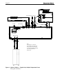
8.1 Installation Warnings .....................................31
8.2 Main Power Connections ...............................31
8.3 Pump Connections and Operation ..................32
8.4 Field Wiring ....................................................33
8.5 Field Connections for single systems .............34
8.6 Field Connections for Lead Lag systems .......34
8.7 Control Panel Layout......................................35
8.8 Building Automation Systems Connections ...36
8.9 Lead Lag Connections ....................................37
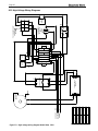
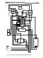
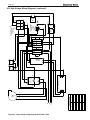
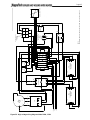
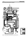
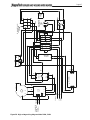
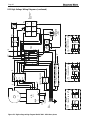
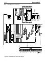
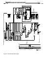
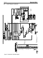
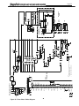
8.10 Wiring Diagrams .......................................38-41
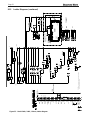
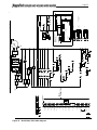
8.11 High Voltage Wiring Diagrams .................42-48
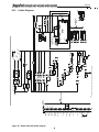
8.12 Ladder Diagrams ......................................49-55

Section 9 – NAVIGATING THE TOUCH SCREEN
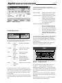
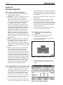
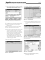
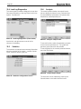
9.1 The Touch Screen ..........................................56
9.2 Using the Touch Screen ..................................56
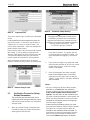
9HUL¿FDWLRQ3URFHVVIRU6DIHW\5HODWHG
Parameters ......................................................58
9.4 While Operating - Checking Individual
Parameters ......................................................59
&RQ¿JXULQJ3DUDPHWHUVRQ,QGLYLGXDO
Controllers ...................................................... 60
9.6 Setting the Date and Time on the
System Display......................61
&RQ¿JXUDWLRQ0HQXV$// ..........................62
6\VWHP,GHQWL¿FDWLRQ$FFHVV ......................62
&+&HQWUDO+HDW&RQ¿JXUDWLRQ....................62
2XWGRRU5HVHW&RQ¿JXUDWLRQ .........................62
'+:'RPHVWLF+RW:DWHU&RQ¿JXUDWLRQ ...63
:DUP:HDWKHU6KXWGRZQ&RQ¿JXUDWLRQ ........63
'HPDQG3ULRULW\&RQ¿JXUDWLRQ ...................... 63
0RGXODWLRQ&RQ¿JXUDWLRQ ..............................63
3XPS&RQ¿JXUDWLRQ .......................................63
6WDWLVWLFV&RQ¿JXUDWLRQ ..................................64
9.7.10 High Limits ....................................................64
9.7.11 Stack Limits ....................................................64
9.7.12 Delta T Limits.................................................64
)URVW3URWHFWLRQ&RQ¿JXUDWLRQ .......................64
9.7.14 Burner Control Ignition ..................................65
6\VWHP&RQ¿JXUDWLRQ ..................................... 65
6HQVRU&RQ¿JXUDWLRQ ......................................65
/DJ6ODYH&RQ¿JXUDWLRQ .............................. 66
/HDG0DVWHU&RQ¿JXUDWLRQ .......................... 69
9.8 Parameter Defaults and Ranges .................69-72
&RQ¿JXULQJD*DWHZD\&RQWURO ....................73
9.10 Variable Speed Flow Control (V.S.P.C.) System .74
9.11 Combustion Setup Procedure .........................75
Section 10 - INITIAL STARTUP INSTRUCTIONS
10.1 Filling the Boiler System ................................78
10.2 Initial Operation .............................................79
10.2.1 Initial Burner Operation .................................79
10.2.2 Combustion Setup Procedure .........................79
10.3 Shutting Down the Unit ..................................79
10.4 Restarting the Unit..........................................79
Section 11 – MAINTENANCE
11.1 System Maintenance.......................................80
11.2 Maintenance Notes .........................................80
11.2.1 Burner .............................................................80
11.2.2 Modulating Gas Valve/ Venturi ......................80
11.2.3 Controller .......................................................81
11.2.4 Spark Ignition Electrodes ...............................81
11.2.5 Flame Sensor ..................................................81
11.2.6A Blower Model 1600 ......................................81
11.2.6B Blower Model 4000 ......................................81
11.2.7 Heat Exchanger Tubes ....................................82
11.2.8 Gas Pressure Switches ....................................82
11.2.9 Battery Back Up for Date and Time ...............83
Section 12 – TROUBLESHOOTING
12.1 About Lockouts, Holds, and Alerts ................84
12.1.1 Responding to a Lockout, Hold,
or Alert ............................................................84
12.1.2 Viewing the Lockout and Alert
Histories .........................................................84
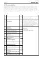
12.2 Troubleshooting Table ...............................86-94
12.3 Diagnostic Tests and Input/Output
Indicators ........................................................ 95
12.4 Lead/Lag Diagnostics .....................................96
12.5 Statistics .........................................................96
12.6 Analysis ..........................................................96
12.7 Control Snapshot ............................................97
12.8 Operating Sequence ........................................97
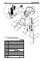
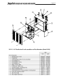
Section 13 – REPLACEMENT PARTS
13.1 General Information .......................................98
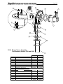
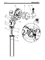
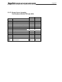
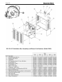
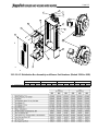
13.2 Component Illustrations, Parts Lists,
and Part Numbers ....................................98-113
13.2.1 Frame and Jacket Assembly ...........................99
13.2.2 Final Assembly .............................................101
13.2.3 Waterway Outlet Assembly ..........................102
13.2.4 Blower Assy, Model 1600 ............................103
13.2.5 Blower Assy, Model 2000 ............................104
%ORZHU$VV\0RGHOV..............105
%ORZHU$VV\0RGHOV..............107
13.2.8 Gas Train Assembly, Models 1600 thru 3000 ...109
*DV7UDLQ$VVHPEO\0RGHOV . . 111
13.2.10 Control Panel Assembly ..............................113
13.2.11 Distribution Box Assemblies ................114-117
ii


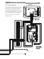
Page 1
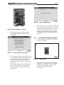
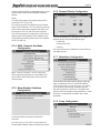
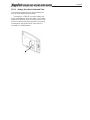
Touch
Screen
Open the
front panel
to access
the Touch
Screen
O
O
O
O
on
f
fr
fr
fr
o
o
Section 1
GENERAL INFORMATION
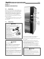
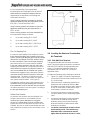
1.1 Introduction
is manual includes information which will help you to
install, operate, and maintain the 1600, 2000, 2500, 3000,
3500 and 4000 MBH systems. Please read this manual
completely before proceeding with the installation. If
you have any questions regarding this equipment, please
consult the manufacturer, or a local manufacturer’s
representative. Many operating problems are caused by
improper installation.
Primary information regarding your unit can be found
on the Rating Plate which is on the outside face of the
right-side panel.
1.2 Safety Notes
DANGER
• Water temperature over 125°F (52°C) can cause
severe burns instantly or death from scalds.
• Children, disabled and elderly are at highest risk of
being scalded.
• See instruction manual before
setting temperature at
heating appliance.
• Feel water before
bathing or showering.
• If this appliance is used
to produce water that
could scald if too hot,
such as domestic hot water
use, adjust the outlet
control (limit) or use temperature limiting valves to
obtain a maximum water temperature of 125°F (52°C).
WARNING
Fire or Explosion Hazard
Improper conguration can cause fuel buildup and
explosion. Improper user operation may result in
property loss, severe physical injury, or death.
Any changes to safety-related conguration parameters
must only be done by experienced and/or licensed
burner/boiler operators and mechanics.
If any odor of gas is detected, or if the gas burner does
not appear to be functioning in a normal manner, close
the main gas shuto valve. Do not shut o the power
switch. Contact your heating contractor, gas company,
or factory representative.
e unit is protected against over-pressurization. A
pressure relief valve is included with each unit.
e inlet gas pressure to the appliance must not exceed 13”
W.C. (3.2 kPa).
All installations must be made in accordance with
1) American National Standard Z223.1/NFPA54-Latest
Edition “National Fuel Gas Code” or
2) CSA B149.1 “Natural Gas and Propane Installation
Code” and with the requirement of the local utility or
other authorities having jurisdiction. Such applicable
requirements take precedence over the general instructions
contained herein.
WARNING
Carbon Monoxide Hazard
Improper adjustment of the burners may lead to poor
combustion quality, increasing the amount of carbon
monoxide produced. Excessive carbon monoxide levels
may lead to personal injury or death.
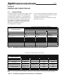
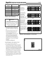
Rating
Plate
R
R

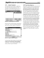
1.4 Warranty
Bradford White MagnaTech boilers and volume
water heaters are covered by a limited warranty. The
owner should complete the warranty registration at
http://www.BradfordWhite.com
ALL WARRANTY CLAIMS must be made by an
authorized Bradford White representative. Claims
must include the serial number and model (this
information can be found on the rating plate). All
claims must also include the installation date and
name of the installer. Shipping costs are not included
in the warranty coverage.
Altitude: Gas input rating of the MagnaTech shall be
used for elevations up to 2000 ft (600 m). The input
rating at elevations above 2000 ft (600 m) shall be
reduced at a rate of 4 percent for each 1000 ft (300 m)
above sea level before selecting the equipment size.
WARNING
Electrical Shock Hazard
Electrical shock can cause severe injury, death or property
damage. Disconnect the power supply before beginning
installation or changing the wiring to prevent electrical shock or
damage to the equipment. It may be necessary to turn o more
than one power supply disconnect.
All electrical wiring is to be done in accordance with local
codes, or in the absence of local codes, with: 1) e National
Electrical Code ANSI/NFPA No. 70 - latest Edition, or 2) CSA
STD. C22.1 “Canadian Electrical Code - Part 1.” is appliance
must be electrically grounded in accordance with these codes.
WARNING
MagnaTech units must be installed in accordance with
the procedures detailed in this manual, or the Bradford
White warranty will be voided. e installation must
conform to the requirements of the local jurisdiction
having authority, and, in the United States, to the latest
edition of the National Fuel Gas Code, ANSI Z223.1/
NFPA54. In Canada, the installation must conform
to the latest edition of CSA B149.1 Natural Gas and
Propane Gas Installation Code, and/or local codes.
Where required by the authority having jurisdiction,
the installation of MagnaTech boilers must conform
to the Standard for Controls and Safety Devices for
Automatically Fired Boilers, ANSI/ASME CSD-1. Any
modications to the boiler, its gas controls, or wiring
may void the warranty. If eld conditions require
modications, consult the factory representative before
initiating such modications.
REVISION
1 -FIRST
2 -SECOND
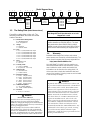
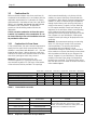
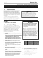
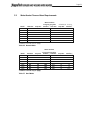
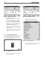
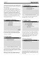
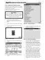
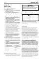
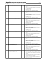
Consult the rating plate on the unit. The
following information describes the model
number structure.
(1-3) Model Series Designation
B = Bradford White
M G = MagnaTech
(4) Usage
H = Hydronic
V = Volume Water
(5-8) Size
1 6 0 0 = 1,600,000 BTU/hr input
2 0 0 0 = 1,999,000 BTU/hr input
2 5 0 0 = 2,499,000 BTU/hr input
3 0 0 0 = 3,000,000 BTU/hr input
3 5 0 0 = 3,500,000 BTU/hr input
4 0 0 0 = 4,000,000 BTU/hr input
(9) Fuel
N = Natural Gas
P = LP Gas
(10) Country Code
X = USA / CANADA
E - Export (CE - non CSA)
(11) Option Code
X = Standard Unit
J = CSD1 Version
(12) Electrical System
A - 110V, (Single Phase)
B - 220V, (Single Phase)
C - 208V, (Three Phase)
D - 480V, (Three Phase)
E - 600V, (Three Phase)
F - 208V, (Single Phase)
(13) Additional Options
X - “H” STAMP (BMGH)
W - “HLW” STAMP (BMGV)
(14) Revision
1 = First, 2 = Second
Model Nomenclature
2 3 4 5 6 7 8 9 10 11 12 13 14
M G
SERIES
B M G
USAGE
H - HYDRONIC
V - VOLUME
WATER
SIZE
MBTU/h
1600
2000
2500
3000
3500
4000
FUEL
N - NATURAL
P - PROPANE
COUNTRY
CODE
X - USA/
CANADA
E - EXPORT
*
OPTIONS CODE
X - STANDARD
J - CSD-1
ELEC SYSTEM
A - 110V, 1Ø
B - 220V, 1Ø
C - 208V, 3Ø
D - 480V, 3Ø
E - 600V, 3Ø
F - 208V, 1Ø
ASME
X - “H” STAMP (BMGH)
W - “HLW” STAMP
(BMGV)
B
1
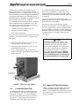
NOTE: Throughout the content of this manual,
the MagnaTech will be referred to as a ‘unit’.
MagnaTech = unit
1.3 The Rating Plate (Model Nomenclature)

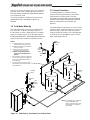
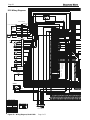
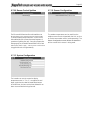
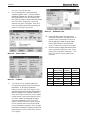
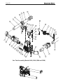
Page 3
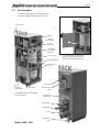
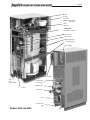
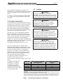
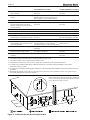
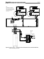
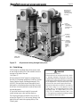
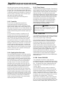
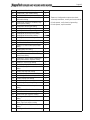
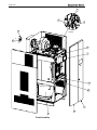
Models 1600 / 2000
Shown with front doors and left side
panels removed.
Manual
Gas Valve
Spark
Generator
Rating Plate
(on outside
of panel)
Blower
Control Panel
On all models, the Control Panel
hinges forward for easy access to
wiring and to the heat exchanger
.
Touch Screen
Heat Exchanger
Condensing
Unit
Air Intake and
Filter
W
ater Outlet
Water Inlet
Vent
Power Pack
o
T
T
T
T
T
T
H
C
U
d
d
P
P
P
Co
C
ntrol
Pane
M
M
G
S
G
S
S
G
R
R
(
M
B
M
M
t
t
t
Condensate
Trap
Gas Supply
Main Power
Connections
er
r
r
s
r
r
r
r
Field
Electrical
Connections
d
d
d
d
d
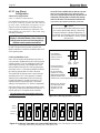
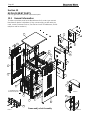
1.5 Unit Overviews
The next 3 pages give a visual reference to
the basic component locations of the unit.

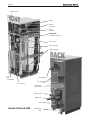
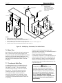
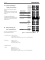
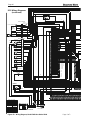
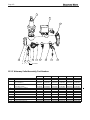
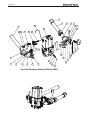
Page 4
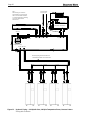
Blower
Models 2500 and 3000
Air Intake and
Filter
Water Outlet
Main Power
Connections
Water Inlet
Vent
Power Pack
Field
Electrical
Connections
d
d
P
s
s
d
d
c
tr
r
i
ic
ic
a
al
i
i
i
l
t
t
t
r
r
s
Condensate
Trap
Heat Exchanger
Condensing Unit
Gas Supply
H
H
H
C
C
C
Manual
Gas Valve
Rating Plate.
(on outside of panel)
R
R
(
Touch Screen
T
T
T
T
T
Spark
Generator
Control Panel
Control

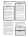
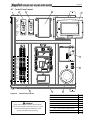
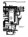
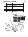
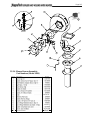
Page 5
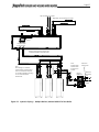
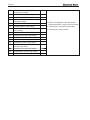
Models 3500 and 4000
Manual
Gas Valve
(hidden behind main
gas valve)
Blower
Touch Screen
B
Air Intake and Filter
Main Power
Connections
Water Outlet
Water Inlet
Vent
Power Pack
Field
Electrical
Connections
P
ns
s
d
d
c
tr
r
i
ic
ic
a
al
i
i
i
l
er
r
r
s
r
r
r
r
r
t
t
t
t
Condensate
Trap
Heat Exchanger
Condensing Unit
Gas Supply
H
H
C
C
C
C
C
G
Rating Plate.
(on outside of panel)
To
T
T
R
R
(o
T
T
T
T
T
T
Spark
Generator
Control Panel
C
C
C
C
C
C

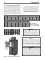
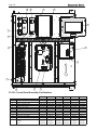
Page 6
E
F
U
B
A
VIEW
REAR
N
Q
S
P
M
R
L
G
H
K
J
T
FRONT
VIEW
SIDE
VIEW
C
D
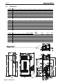
Condensate Trap
Contact
Factory
KpƟonaů
FůanŐes͕
Vent
Gas
6”x3.5”
Touchscreen
ŝspůay
ŝr /nůet
Pressure
ZeůŝeĨ
Vaůǀe
Water
Kutůet
‘Knock-
down’
Height
Water
/nůet
H
J
Gas
ŝr /nůet
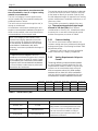
Dodeů ϰϬϬϬ
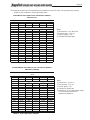
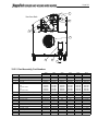
The Dodeů ϰϬϬϬ ǀarŝes Ĩroŵ other sŝnjes ŝn the ůocaƟon oĨ ŝt͛s ŝr /nůet and Gas ^uppůy.
G
K
VIEWREAR
Models 3500 and 4000 differ from the other sizes in the location of their Air Inlet and Gas Supply.
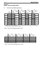
Models 3500 / 4000
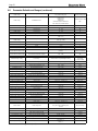
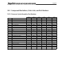
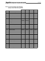
Model
ABCDEFGH
Inches
(
cm
)
1600
29.3 (75)79.8 (203)38 (96)57.5 (147)49.8 (126)4.8 (12)60.8 (154)2.6 (7)
2000
29.3 (75)79.8 (203)38 (96)57.5 (147)49.8 (126)4.8 (12)60.8 (154)2.6 (7)
2500 30.8 (78)
87 (221)41.5 (105)60.5 (154)60.8 (154)6.5 (16)71 (180)4 (10)
3000 30.8 (78)
87 (221)41.5 (105)60.5 (154)60.8 (154)6.5 (16)71 (180)4 (10)
3500
34.5 (88)97 (246)52 (133)70 (178)60.8 (154)6.4 (16)80.8 (205)28.8 (73)
4000
34.5 (88)97 (246)52 (133)70 (178)60.8 (154)6.4 (16)80.8 (205)28.8 (73)
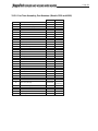
Model
1600
2000
2500
3000
3500
4000
Model
1600
2000
2500
3000
3500
4000
JKLMNPQR
Inches
(
cm
)
8.4 (21)68.4 (171)4 (10)39.2 (100)30.4 (77)16 (41)23 (58)10.2 (26)
8.4 (21)67.4 (171)4 (10)39.2 (100)30.4 (77)16 (41)23 (58)10.2 (26)
9.8 (25)76.4 (194)4.3 (11)44.4 (113)34.5 (88)17.7 (45)27.2 (69)11.8 (30)
9.8 (25)76.8 (195)4.3 (11)44.4 (113)34.5 (88)17.7 (45)27.2 (69)11.8 (30)
26.5 (67) 85.6 (217)6.5 (16)51.3 (130)40 (102)21.6 (55)30.7 (78)13 (33)
26.5 (67) 85.6 (217)6.5 (16)51.3 (130)40 (102)21.6 (55)30.7 (78)13 (33
)
STU
Vent Ø
Air Inlet Ø
Inches
(
cm
)
14 (36)13 (33) 6.3 (16)6 (15)6 (15)60.8 (154)
14 (36)13 (33) 6.3 (16)8 (20)8 (20)60.8 (154)
18.3 (46)14.8 (38)6 (15)8 (20)8 (20)71.0 (180)
18.3 (46)14.8 (38)6 (15)10 (25)10 (25)71.0 (180)
16 (41)17.4 (44) 6.7 (17)
10 (25) 10 (25)
80.8 (205)
16 (41)17.4 (44) 6.7 (17)12 (30)12 (30)80.8 (205)
'Knock-
down'
Height
Water Gas
Condensate
Connection Connection Line
3" Groove Lock
(or flange)
2" NPT 1"
3" Groove Lock
(or flange)
2" NPT 1"
3" Groove Lock
(or flange)
2" NPT 1"
3" Groove Lock
(or flange)
2" NPT 1"
4" Groove Lock
(or flange)
2" NPT 1"
4" Groove Lock
(or flange)
2" NPT 1"
1.6 Dimensions
Figure 1. Dimensions

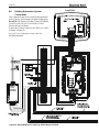
Page 7
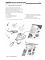
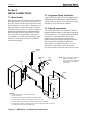
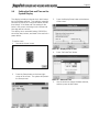
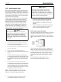
1.7 Unpacking and the Installation Kit
The unit is shipped in a single crate. Carefully
disassemble the crate and inspect the unit for any
damage during shipping. Included in the crate and yet
outside of the unit is the ‘Installation Kit’ box.
Inspect the contents of the box (The Installation Kit),
making sure that all parts are there and not damaged
during shipping.
1. Gromet, Nylon.
2. Box containing Outdoor Sensor
3. Box containing System Sensor
4. Tank Sensor
5. Spring Clip (used to hold tank sensor in sensor well)
1
2
3
4
5
6
7
6. Condensate Trap Assembly (some assembly
required) and document 4312 Condensate Tap
Assembly Instructions.
7. Installation Instructions for Sensors.
NOTE: A condensate neutralizer is NOT included.
Figure 2. The Installation Kit

Page 8
Section 2
LOCATING THE APPLIANCE
2.1 Locating the Appliance
The Unit may be installed indoors or outdoors. If
installing outdoors in a location that may experience
freezing temperatures, precautions must be taken to
prevent water in the heat exchanger and condensate
inside and outside of the boiler from freezing. Damage
due to freezing water or condensate is not covered by
the warranty.
Choose a location for the unit which allows
clearances on all sides for maintenance and
inspection. See Table 1. Always install the unit on a
¿UPOHYHOVXUIDFH,WLVUHFRPPHQGHGWKDWWKHXQLWLV
installed on a raised 4” pad so that there is elevation for
a condensate neutralizer kit (not included with unit).
The unit should not be located in an area where
leakage of any connections will result in damage to
WKHDUHDDGMDFHQWWRWKHDSSOLDQFHRUWRORZHUÀRRUV
of the structure.
When this type of location is not available, install a
suitable drain pan, adequately drained, under the
appliance.
7KHDSSOLDQFHLVGHVLJQFHUWL¿HGE\&6$
,QWHUQDWLRQDOIRULQVWDOODWLRQRQFRPEXVWLEOHÀRRULQJ
LQEDVHPHQWVLQXWLOLW\URRPVRUDOFRYHV. Boilers
must never be installed on carpeting. The location
for the appliance should be chosen with regard to
the vent pipe lengths and external plumbing.
The unit shall be installed such that the gas ignition
system components are protected from water
(dripping, spraying, rain, etc.) during operation and
service (circulator replacement, control replacement,
etc.).
When vented vertically, the Unit must be located as
close as practical to the vertical section of the vent.
If the vent terminal and/or combustion air terminal
terminate through a wall, and there is potential for
snow accumulation in the local area, both terminals
should be installed at an appropriate level above
grade or the maximum expected snow line.
The dimensions and requirements that are shown in
Table 1. should be met when choosing the locations
for the appliance.
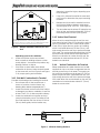
2.2 Correct Vent Distance from
Outside Wall or Roof Termination
The forced draft combustion air blower in the
DSSOLDQFHKDVVXI¿FLHQWSRZHUWRYHQWSURSHUO\ZKHQ
the guidelines in Table 2 are followed.
Note - When located on the same wall, the Unit
combustion air intake terminal must be installed a
minimum of 12” (
30cm) below the exhaust terminal.
There must also be a minimum horizontal distance
from intake to the exhaust terminal
of 84” (
213cm) See Figure 5
APPLIANCE SUGGESTED SERVICE ACCESS CLEARANCE
SURFACE INCHES CM
Front 24 61
Left Side 8 20
Right Side 8 20
Back 24 61
Top, 1600 & 2000 12 30
Top, 2500 & 3000 15 38
Top, 4000 24 61
APPLIANCE REQUIRED CLEARANCE TO COMBUSTIBLES
SURFACE INCHES CM
Front 18 45
Left Side 4 15
Right Side 4 15
Back 11 15
Top 1 2.5
Vent 1 2.5
Table 1. Clearances
INTAKE / EXHAUST
MAX EQUIVALENT
SIZE DIAMETER FT. M
1600 6” 100 30
2000 & 2500 8” 100 30
3000 & 3500 10” 100 30
4000 12” 100 30
Combustion Intake and Vent must be the same size.
Installations in the U.S. require exhaust vent pipe that is CPVC
complying with ANSI/ASTM D1785 F441, polypropylene
complying with ULC S636, or stainless steel complying with
UL1738. Installations in Canada require exhaust vent pipe that
LVFHUWL¿HGWR8/&6
Intake (air) pipe must be PVC or CPVC that complies with
ANSI/ASTM D1785 F441, ABS that complies with ANSI/ASTM
D1527, stainless steel, or galvanized material.
To calculate max equivalent length, measure the linear feet of
the pipe, and add 5 feet (1.5 m) for each elbow used.
Table 2. Vent / Air Pipe Sizes

Page 9
Table 3. Allowable Single Wall Stainless Steel Vent Suppliers and Part Numbers
Table 4. Allowable Polypropylene Vent Manufacturers / Trade Names
Selkirk DuraVent NovaFlex
Safe-T Vent EZ Seal FasNSeal Z Flex
90° Elbow 9x14 FSELB90xx 2SVEExx90
Pipe 9x07 FSVLxxxx 2SVEPxxxx
Boiler Adapter 5x01BOI FSAAUx
2SVSAxx (OD)
2SVSTTAxx (ID)
Horizontal TerminaƟon (bird screen) 9x92 FSBSx 2SVSTPXxx
VerƟcal TerminaƟon (rain cap) 5X00CI FSRCx 2SVSRCxx
Inlet Air TerminaƟon 9xTERM FSAIHXX* 2SVSTEXxx90
FSA-xxFNSM-xPVCF
Adapter SS to PP FSAAUx-xPP 2ZDCPVCx**
*4", 6" & 7" only **up to 6"
Example Components
Trade Name / Model
NOTE:
“x”, “xx”, and “xxxx” refer to variaƟons in nominal size. See manufacturer’s catalog for a parƟcular applicaƟon.
CentroTherm DuraVent Selkirk NovaFlex
InnoFlue PolyPro PolyFlue Z-Dens
Single Wall Pipe ISVLxxxx xPPS-x 83x002 ZDPx
Elbow ISELxxxx xPPS-E90L 83x08 2ZDEx87
PVC Adapter ISAMGTxxxx
xPPS-ADL (to 4")
xPPS-xxPVCM-xPPF (>4")
83x040 2ZDCPVCx
Horizontal TerminaƟon (bird screen)
IASPPxx (2" - 4")
IASSSxx (5" - 12")
xPPS-BG (2" - 6") 83x050 2ZDESx
VerƟcal TerminaƟon
IASPPxx (2" - 4")
IASSSxx (5" - 12")
xPPS-VKL (<5")
xPPS-VTML (5"-8")
83x050 2ZDESx
Air Inlet 2ZDESx
Trade Name / Model
Example Components
3.1 General Venting
This product requires a special venting system. Refer
to venting supplier’s instructions for complete parts
list and method of installation. The manufacturers
and product lines listed on the following tables have
been tested and authorized to safely operate with
this equipment. Suppliers of stainless steel and
polypropylene venting that are not listed on these
tables are not permitted for use with
vent category III & IV products.
Manufacturer Model Numbers (abreviated)
Manufacturer Model Numbers (abreviated)
Section 3
VENTING AND COMBUSTION AIR
Do not mix venting suppliers and models in venting
systems. Failure to comply could result in personal
injury, property damage, or death.
Installations must comply with applicable national,
state and local codes.

Page 10
shall communicate directly, or by ducts, with the
outdoors or spaces that freely communicate with
the outdoors. When directly communicating with the
outdoors, or when communicating to the outdoors
through vertical ducts, each opening shall have a
minimum free area of 1 square inch per 4000 Btu/
hr (550 square mm/kW) of total input rating of all
equipment in the enclosure. When communicating
to the outdoors through horizontal ducts, each
opening shall have a minimum free area of not less
than 1 square inch per 2000 Btu/hr (1100 square
mm/kW) of total input rating of all equipment in the
enclosure.
Method 2: One permanent opening, commencing
within 12” (300 mm) of the top of the enclosure,
shall be permitted. The opening shall directly
communicate with the outdoors or shall
communicate through a vertical or horizontal duct
to the outdoors or spaces that directly communicate
with the outdoors and shall have a minimum free
area of 1 square inch per 3000 Btu/hr (734 square
mm/kW) of the total input rating of all equipment
located in the enclosure. This opening must not be
less than the sum of the areas of all vent connectors
LQWKHFRQ¿QHGVSDFH
3.2 Combustion Air
Boilers and water heaters must have provisions for
combustion and ventilation air in accordance with the
applicable requirements for Combustion Air Supply
and Ventilation in the National Fuel Gas Code, ANSI
=RULQ&DQDGDWKH1DWXUDO*DVDQG3URSDQH
Installation Code, CSA B149.1. All applicable
provisions of local building codes must also be
adhered to.
A Units can take combustion air from the space
in which it is installed, or the combustion air can
be ducted directly to the unit. Ventilation air must
be provided in either case.
3.2.1 Combustion Air From Room
In the United States, the most common requirements
specify that the space shall communicate with the
outdoors in accordance with Method 1 or 2. (See the
following descriptions.) Where ducts are used, they
shall be of the same cross-sectional area as the free
area of the openings to which they connect.
Method 1: Two permanent openings, one
commencing within 12” (300 mm) of the top and
one commencing within 12” (300 mm) of the bottom,
of the enclosure shall be provided. The openings
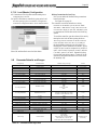
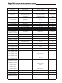
Table 5. Ducted Air Accessories
Model 1600 Model 2000 Model 2500 Model 3000 Model 3500 Model 4000
Screen for horizontal galvanized air pipe D2012104 D2012101 D2012101 D2012102 D2012103 D2012103
Screen for horizontal PVC air pipe CA012004 CA012001 CA012001 CA012002 CA012003 CA012003
Screen for horizontal polypropylene air pipe CA012204 CA012201 CA012201 CA012202 CA012203 CA012203
Screen for vertical galvanized air pipe D2012204 D2012201 D2012201 D2012202 D2012203 D2012203
Screen for vertical PVC air pipe CA012404 CA012401 CA012401 CA012402 CA012403 CA012403
Screen for vertical polypropylene air pipe CA012604 CA012601 CA012601 CA012602 CA012603 CA012603
Table 6. Required Combustion Air Pipe Material
Material United States Canada
ABS ANSI/ASTM D1527 The air pipe material must be chosen based upon
the intended application of the boiler or water
heater, and must be installed according to the vent
manufacturer’s installation instructions.
PVC, sch. 40 ANSI/ASTM D1785 or D2665
CPVC, sch. 40 ANSI/ASTM F441
Single wall galv. steel 26 gauge
Polypropylene ULC S636 Class 2C

Page 11
Other methods of introducing combustion and
ventilation air are acceptable, providing they conform
to the requirements in the applicable codes listed
above.
In Canada, consult local building and safety codes
or, in absence of such requirements, follow CAN/
CSA B149.
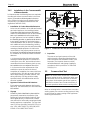
3.2.2 Ducted Combustion Air
The combustion air can be taken through the wall, or
through the roof. Manufacturer offers accessories to
use with ducted air systems, as shown in Table 5.
See Table 6 to select the appropriate diameter air
SLSH:KHQWDNHQIURPWKHURRID¿HOGVXSSOLHG
rain cap or an elbow arrangement must be used to
prevent entry of rain water. (See Figure 7).
Use ABS, PVC, CPVC, polypropylene, stainless
steel, or galvanized pipe for the combustion air
intake (See Table 6). The intake must be sized per
Table 2. Route the intake to the boiler as directly
as possible. Seal all joints. Provide adequate
hangers. The unit must not support the weight of the
combustion air intake pipe. The maximum equivalent
pipe length allowed is 100 feet (30 m).
Each elbow is considered to be 5 feet (1.5m)
When using polypropylene or stainless steel
PDWHULDOVLQKRUL]RQWDOGXFWFRQ¿JXUDWLRQVDVLQJOH
elbow must be installed on the end of the air inlet
to act as an outdoor terminal. In vertical duct
applications, two elbows must be installed on the
end of the inlet to act as a vent terminal. When
elbows are use as terminals, appropriate screens
must be installed to prevent blockage.
The elbow(s) required for termination are not
included in the kits sown in Table 5
The connection for the intake air pipe is on the back
panel.
In addition to air needed for
combustion, air shall also
be supplied for ventilation,
including air required for
comfort and proper working
conditions for personnel. Refer
to the applicable codes.
3.3 Venting
WARNING
Selection of improper vent materials for
installations that are installed in closets, or will be
operated in high ambient temperature levels, may
lead to property damage, personal injury, or death.
WARNING
Failure to use the appropriate vent material,
installation techniques, or glues and sealants
could lead to vent failure causing property
damage, personal injury or death.
WARNING
Use of cellular core PVC (ASTM F891), cellular
core CPVC, or Radel® (polyphenolsulfone) in
non-metallic venting systems is prohibited and that
FRYHULQJQRQPHWDOOLFYHQWSLSHDQG¿WWLQJVZLWK
thermal insulation is prohibited.
WARNING
All venting must be installed according to this
manual and any other applicable local codes,
including but not limited to, ANSI Z223.1/NFPA 54,
CSA B149.1, CSAB149.2 and ULC S636. Failure
to follow this manual and applicable codes may
lead to property damage, severe injury, or death.
Table 7. Vent Sizing for Category II - Gravity Vent
ggygy
Boiler Model Vent Connection Size Diameter
(provided with boiler)
Vent Connector Size Diameter
(Increaser*)
MGH/V1600 6” 14”
MGH/V2000 8” 14”
MGH/V2500 8” 18”
MGH/V3000 10” 18”
MGH/V3500 10” 22”
MGH/V4000 12 22”
WARNING: Vent must be installed with appropriate condensate traps and using only specific
manufacturers, models and materials outlined in this manual.
Draft must always remain between -0.1” and -0.001” at all firing rates. If pressures outside of
this range are measured, consult professional venting engineer for recommendations, such as
double-acting barometric dampers to avoid reduced performance or hazardous conditions.

Page 12
If the system temperatures are unknown at the
time of installation, class IIC or higher venting
material is recommended.
The Unit is a Category II and IV appliance and
may be installed with vent materials meeting the
standards listed on Table 9.
The unit’s vent can terminate through the roof, or
through an outside wall.
All installations must be done following the vent
supplier’s recommended installation techniques. If
these are not available, refer to the Manufacturer
recommendations for the material used.
NOTE: For Category II and IV boilers, have
horizontal runs sloping upwards not less than
1/4 inch per foot (21 mm/m) from the boiler to
WKHYHQWWHUPLQDOEHLQVWDOOHGVRDVWRSUHYHQW
DFFXPXODWLRQRIFRQGHQVDWHDQGZKHUH
necessary, have means provided for drainage of
condensate.
ATTENTION: Pour la catégorie II & IV, les
chaudières ont horizontal en pente vers le haut au
moins 1/4 de pouce par pied (21 mm/m) à partir
GHODFKDXGLqUHSRXUO¶pYHQWERUQHrWUHLQVWDOOp
GHIDoRQjpYLWHUO¶DFFXPXODWLRQGHFRQGHQVDWV
et, le cas échéant, ont des moyens prévus pour
l’évacuation des condensats.
The venting must be correct to allow the condensate
to run back to the Unit to drain. Route the vent pipe
to the heater as directly as possible. Seal all joints.
Provide adequate hangers as required in the venting
system manufacturer’s Installation Instructions, or at
least every 4 feet.
The unit must not support the weight of the vent
pipe. The maximum equivalent pipe length
allowed is 100 feet (30m).
Each elbow is
considered to be 5 feet (1.5m). Manufacturer offers
accessory kits to use with horizontal and vertical
exhaust vent systems, as shown in Table 8
3.3.1 Common Venting
This unit can be common vented, however, the
common venting must be a professionally designed
and approved system. See Venting Document 1396.
pdf available online.
Catagory II and IV units are never permitted to
share a vent with any Catagory 1 appliances.
3.3.3 Venting Requirements Unique to
Canada
7KHVHKLJKHI¿FLHQF\ERLOHUVDQGZDWHUKHDWHUV
are Vent Category II and IV appliances. Per the
requirements of CAN/CSA-B149.1, only BH vent
systems can be connected to these units and
VXFKYHQWV\VWHPVHLWKHU8/&6FHUWL¿HG
VWDLQOHVVVWHHORURWKHU8/&6FHUWL¿HG%+
vent (eg. plastics) must be installed per the vent
PDQXIDFWXUHU¶VFHUWL¿HGLQVWDOODWLRQLQVWUXFWLRQV
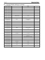
Table 8. Vent Accessory Kits
Model 1600 Model 2000 Model 2500 Model 3000 Model 3500 Model 4000
Horizontal vent terminal for stainless steel D2012004 D2012001 D2012001 D2012002 D2012003 D2012003
Screen for horizontal CPVC vent CA012104 CA012101 CA012101 CA012102 CA012103 CA012103
Screen for vertical stainless steel vent D2012304 D2012301 D2012301 D2012302 D2012303 D2012303
Screen for vertical CPVC vent CA012504 CA012501 CA012501 CA012502 CA012503 CA012503
Installation Standards
Material United States Canada
Stainless steel UL 1738
9HQWLQJPXVWEH8/&6FHUWL¿HGIRUXVHDV
venting material. The venting material class must
be chosen based upon the intended application
of the unit, and must be installed according to
WKHPD[LPXPÀXHJDVWHPSHUDWXUHDQGWKHYHQW
manufacturer’s instructions.
CPVC, sch 40 ANSI/ASTM F441
Polypropylene ULC S636 Class 2C
Table 9. Required Exhaust Vent Material

Page 13
It is the responsibility of the appropriately
licensed technician installing this unit to use ULC
6FHUWL¿HGYHQWPDWHULDOFRQVLVWHQWZLWKWKH
requirements as described in the Venting and
Combustion Air section.
&ODVV,YHQWLQJV\VWHPVDUHVXLWDEOHIRUJDV¿UHG
DSSOLDQFHVSURGXFLQJÀXHJDVWHPSHUDWXUHRIPRUH
than 135°C, but not more than 245°C.
&ODVV,,YHQWLQJV\VWHPVDUHVXLWDEOHIRUJDV¿UHG
DSSOLDQFHVSURGXFLQJÀXHJDVWHPSHUDWXUHVRI
135°C or less.
&ODVV,,YHQWLQJV\VWHPVDUHIXUWKHUFODVVL¿HGLQWR
four temperature ratings as follows:
A Up to and including 65°C / 149°F
B Up to and including 90°C / 194°F
C Up to and including 110°C / 230°F and
D Up to and including 135°C / 275°F
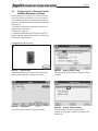
Flue Gas Sampling Port -
It is also the responsibility of the installer to ensure
WKDWDÀXHJDVVDPSOLQJSRUWLVLQVWDOOHGLQWKHYHQW
V\VWHP7KLVÀXHJDVVDPSOLQJSRUWPXVWEHLQVWDOOHG
QHDUWKHÀXHFRQQHFWLRQRIWKH8QLWZLWKLQIHHWRI
WKHÀXHFRQQHFWLRQ7KHUHLVQRÀXHJDVVDPSOLQJ
port internal to the Unit, so one must be installed
LQWKHYHQWV\VWHPH[WHUQDOWRWKH8QLW$ÀXHJDV
sampling port available as a component of the ULC
6FHUWL¿HGYHQWV\VWHPLVSUHIHUUHG+RZHYHULI
RQHLVQRWDYDLODEOHZLWKWKHFHUWL¿HGYHQWV\VWHP
Manufacturer suggests using a tee with the branch
FRQQHFWLRQVL]HGWRDOORZIRULQVHUWLRQRIDÀXHJDV
analyzer probe. The branch connection must be
resealable with a cap or other means to ensure the
vent system remains sealed. (See Figure 3)
Consideration must be given to the placement and
RULHQWDWLRQRIWKHÀXHJDVVDPSOLQJSRUWWRHQVXUH
WKDWFRQGHQVDWHLVIUHHWRÀRZEDFNLQWRWKH8QLWDQG
not collect anywhere in the vent system - including in
WKHÀXHJDVVDPSOLQJSRUW
Exhaust Vent Terminal -
An exhaust vent terminal must be installed. If an
exhaust vent terminal is not available with the
FHUWL¿HGYHQWV\VWHP0DQXIDFWXUHUVXJJHVWV
WKHXVHRIDFRXSOHU¿WWLQJIURPWKHFHUWL¿HGYHQW
system into which the vent terminal screen can be
installed. Be sure to install and terminate both vent
and combustion air pipes per the instructions in this
section.
3.4 Locating the Vent and Combustion
Air Terminals
3.4.1 Side Wall Vent Terminal
The appropriate side wall vent terminal must be
used. The terminal must be located in accordance
with ANSI Z223.1/NFPA 54 and applicable local
codes. In Canada, the installation must be in
accordance with CSA B149.1 or .2 and local
applicable codes.
Consider the following when installing the terminal:
1. Figure 5 on page 15 shows the requirements
for mechanical vent terminal clearances for the
U.S. and Canada.
2. Vent terminals for condensing appliances or
appliances with condensing vents are not
permitted to terminate above a public walkway,
or over an area where condensate or vapor
could create a nuisance or hazard.
3. Locate the vent terminal so that vent gases
cannot be drawn into air conditioning system
inlets.
4. Locate the vent terminal so that vent gases
cannot enter the building through doors,
windows, gravity inlets or other openings.
Whenever possible, avoid locations under
windows or near doors.
5. Locate the vent terminal so that it cannot
be blocked by snow. The installer may
determine that a vent terminal must be
higher than the minimum shown in codes,
Figure 3. Test Port

Page 14
*When vent terminal is less than 10 feet (3 m) horizontally
from a forced air inlet, the terminal must be at least 3 feet
(0.9 m) above the air inlet. (US only)
Figure 4. Combustion Air and Vent Through Side Wall
U.S. Installations (see note 1) Canadian Installations (see note 2)
A= Clearance above grade, veranda, porch, 12 inches (30 cm) 12 inches (30 cm)
deck, or balcony See note 6 See note 6
B= &OHDUDQFHWRZLQGRZRUGRRUWKDWPD\EH 'LUHFWYHQWRQO\LQFKHVFP LQFKHVFP
opened Other than Direct vent: 4 ft (1.2m) below or to
VLGHRIRSHQLQJIWFPDERYHRSHQLQJ
C= Clearance to permanently closed window See note 4 See note 5
D= 9HUWLFDOFOHDUDQFHWRYHQWLODWHGVRI¿WORFDWHG
above the terminal within a horizontal See note 4 See note 5
distance of 2 feet (61 cm) from the center
line of the terminal
E= &OHDUDQFHWRXQYHQWLODWHGVRI¿W 6HHQRWH 6HHQRWH
F= Clearance to outside corner See note 4 See note 5
G= Clearance to inside corner See note 4 See note 5
H= Clearance to each side of center line 3 feet (91 cm) within a height 15 feet
extended above meter/regulator assembly See note 4 above the meter/regulator assembly
I= Clearance to service regulator vent outlet See note 4 3 feet (91 cm)
J= Clearance to nonmechanical air supply Direct vent only: 36” (91cm)
inlet to building or the combustion air inlet Other than Direct vent: 4 ft (1.2m) below 36 inches (91 cm)
WRDQ\RWKHUDSSOLDQFH RUWRVLGHRIRSHQLQJIWFPDERYHRSHQLQJ
K= Clearance to a mechanical air supply inlet 3 feet (91 cm) above if within 10 feet (3 m) 6 feet (1.83 m)
horizontally
L= Clearance above paved sidewalk or paved Vent termination not allowed in this location 7 ft (2.1 m)
driveway located on public property for category IV appliances. See note 5
M= Clearance under veranda, porch, deck, See note 4 12 inches (30 cm)
or balcony See note 5
Notes:
1. In accordance with the current ANSI Z223.1 / NFPA 54 National Fuel Gas Code.
2. In accordance with the current CAN/CSA-B149 Installation Codes.
3. Permitted RQO\LIYHUDQGDSRUFKGHFNRUEDOFRQ\LVIXOO\RSHQRQDPLQLPXPRIWZRVLGHVEHQHDWKWKHÀRRU
)RUFOHDUDQFHVQRWVSHFL¿HGLQ$16,=1)3$FOHDUDQFHLVLQDFFRUGDQFHZLWKORFDOLQVWDOODWLRQFRGHVDQGWKH
requirements of the gas supplier.
)RUFOHDUDQFHVQRWVSHFL¿HGLQ&$1&6$%FOHDUDQFHLVLQDFFRUGDQFHZLWKORFDOLQVWDOODWLRQFRGHVDQGWKHUHTXLUHPHQWVRIWKH
gas supplier.
6. IMPORTANT: All terminals must be placed so that they remain a minimum 12” above expected snow line. Local codes may have
PRUHVSHFL¿FUHTXLUHPHQWVDQGPXVWEHFRQVXOWHG

Page 15
determine it should be higher, depending upon
local conditions.
4. If the Unit is side-wall vented to the same wall,
use Figure 5 to determine the proper mounting
locations.
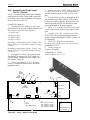
5. Multiple vent kits should be installed such that
the horizontal distance between outlet group
and inlet group is 84” (213 cm). (See Figure 6)
6. The vent outlet must be at least 12” above the top
of the air inlet, and must be at least 84” (213 cm)
horizontally from the air inlet. (See Figure 6).
3.4.3 Vertical Vent Terminal
When the unit is vented through the roof, the vent
must extend at least 3 feet (0.9 m) above the point at
which it penetrates the roof. It must extend at least
2 feet (0.6 m) higher than any portion of a building
within a horizontal distance of 10 feet (3.0 m), and
high enough above the roof line to prevent blockage
from snow. The vent terminal offered with the Unit can
be used in both vertical and horizontal applications.
When the combustion air is taken from the roof, the
combustion air must terminate at least 12” (30 cm)
below the vent terminal.
3.4.4 Vertical Combustion Air Terminal
:KHQFRPEXVWLRQDLULVWDNHQIURPWKHURRID¿HOG
supplied rain cap or an elbow arrangement must be
used to prevent entry of rain water. The opening on
the end of the terminal must be at least 12” (30 cm)
above the point at which it penetrates the roof, and
high enough above the roof line to prevent blockage
from snow. When the vent terminates on the roof, the
combustion air must terminate at least 12” (30 cm)
below the vent terminal.
84”
213
12”
Figure 5. Minimum Venting Distance
IMPORTANT: All terminals must be placed so that they remain at least 12”
above the expected snow line. Local codes may have more specic
requirements, and must be consulted. Refer to the NFPA54 National Fuel Gas
Code and your local codes for all required clearances for venting.
84
Figure 6. Multiple Side-Wall Terminals, Air and
Vent
depending upon local conditions.
6. Locate the terminal so the vent exhaust
does not settle on building surfaces or other
nearby objects. Vent exhaust bi-products may
damage surfaces or objects.
7. If the boiler or water heater uses ducted
combustion air from an intake terminal located
on the same wall, see See Figure 6 and Figure
5 for proper spacing and orientation.
3.4.2 Side Wall Combustion Air Terminal
Consider the following when installing the terminal.
1. Do not locate the air inlet terminal near a
source of corrosive chemical fumes (e.g.,
FOHDQLQJÀXLGFKORULQHFRPSRXQGVHWF
2. Locate the terminal so that it will not be subject
to damage by accident or vandalism. It must be
at least 7 feet ( 2.1 m) above a public walkway.
3. Locate the combustion air terminal so that it
cannot be blocked by snow. The National Fuel
Gas Code requires that it be at least 12 inches
(30 cm) above grade, but the installer may

Page 16
3.4.5 Installations in the Commonwealth
of Massachusetts
In Massachusetts the following items are required if
the side-wall exhaust vent termination is less than
VHYHQIHHWDERYH¿QLVKHGJUDGHLQWKHDUHD
of the venting, including but not limited to decks
and porches. (From Massachusetts Rules and
regulations 248 CMR 5.08.)
1. Installation of Carbon Monoxide Detectors
At the time of installation of the side wall vented
gas fueled appliance, the installing plumber
RUJDV¿WWHUVKDOOREVHUYHWKDWDKDUGZLUHG
carbon monoxide detector with an alarm battery
EDFNXSLVLQVWDOOHGRQWKHÀRRUOHYHOZKHUH
the gas appliance is to be installed. In addition,
WKHLQVWDOOLQJSOXPEHURUJDV¿WWHUVKDOOREVHUYH
that a battery operated or hard-wired carbon
monoxide detector with an alarm is installed on
each additional level of the dwelling, building
or structure served by the side-wall horizontally
vented gas fueled equipment. It shall be the
responsibility of the property owner to secure
WKHVHUYLFHVRITXDOL¿HGOLFHQVHGSURIHVVLRQDOV
for installation of hard-wired carbon monoxide
detectors.
a. In the event that the side-wall horizontally
vented gas fueled equipment is installed in a
crawl space or an attic, the hard-wired carbon
monoxide with alarm and battery back-up may
EHLQVWDOOHGRQWKHQH[WDGMDFHQWÀRRUOHYHO
b. In the event that the requirements of the
subdivision cannot be met at the time of
completion of installation, the owner shall have
a period of thirty (30) days to comply with the
above requirements, provided, however, that
during said thirty (30) day period, a battery
operated carbon monoxide detector with an
alarm be installed.
2. Approved Carbon Monoxide Detectors
Each carbon monoxide detector shall comply
with NFPA 720 and be ANSI/UL 2034 listed and
,$6FHUWL¿HG
3. Signage
$PHWDORUSODVWLFLGHQWL¿FDWLRQSODWHVKDOOEH
permanently mounted to the exterior of the
building at a minimum height of eight (8) feet
above grade directly in line with the exhaust
vent terminal for horizontally vented gas fueled
heating appliance or equipment. The sign shall
read, in print no less than one-half (1/2) inch in
size: “GAS VENT DIRECTLY BELOW, KEEP
CLEAR OF ALL OBSTRUCTIONS.”
4. Inspection
The state or local gas inspector of the side-
wall horizontally vented gas fueled appliance
shall not approve the installation unless, upon
inspection, the inspector observes carbon
monoxide detectors and signage installed in
accordance with the provisions of 248 CMR
5.08(2)(a) 1-4.
3.5 Common Vent Test
Note -This section does not describe a method for
common venting the units. It describes what must
be done when a unit is removed from a common
vent system. Units require special vent systems
and fans for common vent. Contact the factory if
you have questions about common venting units.
When an existing boiler is removed from a common
venting system, the common venting system is likely
to be too large for proper venting of the appliances
remaining connected to it.
Figure 7. Combustion Air and Vent Through Roof
*
*
*
*
*
*
In Canada, refer to CAN/CSA B199.1
La page est en cours de chargement...
La page est en cours de chargement...
La page est en cours de chargement...
La page est en cours de chargement...
La page est en cours de chargement...
La page est en cours de chargement...
La page est en cours de chargement...
La page est en cours de chargement...
La page est en cours de chargement...
La page est en cours de chargement...
La page est en cours de chargement...
La page est en cours de chargement...
La page est en cours de chargement...
La page est en cours de chargement...
La page est en cours de chargement...
La page est en cours de chargement...
La page est en cours de chargement...
La page est en cours de chargement...
La page est en cours de chargement...
La page est en cours de chargement...
La page est en cours de chargement...
La page est en cours de chargement...
La page est en cours de chargement...
La page est en cours de chargement...
La page est en cours de chargement...
La page est en cours de chargement...
La page est en cours de chargement...
La page est en cours de chargement...
La page est en cours de chargement...
La page est en cours de chargement...
La page est en cours de chargement...
La page est en cours de chargement...
La page est en cours de chargement...
La page est en cours de chargement...
La page est en cours de chargement...
La page est en cours de chargement...
La page est en cours de chargement...
La page est en cours de chargement...
La page est en cours de chargement...
La page est en cours de chargement...
La page est en cours de chargement...
La page est en cours de chargement...
La page est en cours de chargement...
La page est en cours de chargement...
La page est en cours de chargement...
La page est en cours de chargement...
La page est en cours de chargement...
La page est en cours de chargement...
La page est en cours de chargement...
La page est en cours de chargement...
La page est en cours de chargement...
La page est en cours de chargement...
La page est en cours de chargement...
La page est en cours de chargement...
La page est en cours de chargement...
La page est en cours de chargement...
La page est en cours de chargement...
La page est en cours de chargement...
La page est en cours de chargement...
La page est en cours de chargement...
La page est en cours de chargement...
La page est en cours de chargement...
La page est en cours de chargement...
La page est en cours de chargement...
La page est en cours de chargement...
La page est en cours de chargement...
La page est en cours de chargement...
La page est en cours de chargement...
La page est en cours de chargement...
La page est en cours de chargement...
La page est en cours de chargement...
La page est en cours de chargement...
La page est en cours de chargement...
La page est en cours de chargement...
La page est en cours de chargement...
La page est en cours de chargement...
La page est en cours de chargement...
La page est en cours de chargement...
La page est en cours de chargement...
La page est en cours de chargement...
La page est en cours de chargement...
La page est en cours de chargement...
La page est en cours de chargement...
La page est en cours de chargement...
La page est en cours de chargement...
La page est en cours de chargement...
La page est en cours de chargement...
La page est en cours de chargement...
La page est en cours de chargement...
La page est en cours de chargement...
La page est en cours de chargement...
La page est en cours de chargement...
La page est en cours de chargement...
La page est en cours de chargement...
La page est en cours de chargement...
La page est en cours de chargement...
La page est en cours de chargement...
La page est en cours de chargement...
La page est en cours de chargement...
La page est en cours de chargement...
-
 1
1
-
 2
2
-
 3
3
-
 4
4
-
 5
5
-
 6
6
-
 7
7
-
 8
8
-
 9
9
-
 10
10
-
 11
11
-
 12
12
-
 13
13
-
 14
14
-
 15
15
-
 16
16
-
 17
17
-
 18
18
-
 19
19
-
 20
20
-
 21
21
-
 22
22
-
 23
23
-
 24
24
-
 25
25
-
 26
26
-
 27
27
-
 28
28
-
 29
29
-
 30
30
-
 31
31
-
 32
32
-
 33
33
-
 34
34
-
 35
35
-
 36
36
-
 37
37
-
 38
38
-
 39
39
-
 40
40
-
 41
41
-
 42
42
-
 43
43
-
 44
44
-
 45
45
-
 46
46
-
 47
47
-
 48
48
-
 49
49
-
 50
50
-
 51
51
-
 52
52
-
 53
53
-
 54
54
-
 55
55
-
 56
56
-
 57
57
-
 58
58
-
 59
59
-
 60
60
-
 61
61
-
 62
62
-
 63
63
-
 64
64
-
 65
65
-
 66
66
-
 67
67
-
 68
68
-
 69
69
-
 70
70
-
 71
71
-
 72
72
-
 73
73
-
 74
74
-
 75
75
-
 76
76
-
 77
77
-
 78
78
-
 79
79
-
 80
80
-
 81
81
-
 82
82
-
 83
83
-
 84
84
-
 85
85
-
 86
86
-
 87
87
-
 88
88
-
 89
89
-
 90
90
-
 91
91
-
 92
92
-
 93
93
-
 94
94
-
 95
95
-
 96
96
-
 97
97
-
 98
98
-
 99
99
-
 100
100
-
 101
101
-
 102
102
-
 103
103
-
 104
104
-
 105
105
-
 106
106
-
 107
107
-
 108
108
-
 109
109
-
 110
110
-
 111
111
-
 112
112
-
 113
113
-
 114
114
-
 115
115
-
 116
116
-
 117
117
-
 118
118
-
 119
119
-
 120
120


Bradford White BMGH2000 Manuel utilisateur
- Catégorie
- Chauffe-eau
- Taper
- Manuel utilisateur
dans d''autres langues
- English: Bradford White BMGH2000 User manual
Documents connexes
-
Bradford White BNTH-399 Manuel utilisateur
-
Bradford White BNTV-600 Manuel utilisateur
-
-
-
Bradford White BCFH3000 Manuel utilisateur
-
-
Bradford White BMGH1600 Manuel utilisateur
-
-
Bradford White Brute LX BLXCW-125 Manuel utilisateur
-
Autres documents
-
Dunkirk DWB Series Installation, Operation & Maintenance Manual
-
STA-RITE MIB0715B, MIB0715S Intelliboost Le manuel du propriétaire
-
Raypak XVers L 406L-856L Type H Mode d'emploi
-
-
Laars NeoTherm NTH User Information
-
-
Mitsubishi Heavy Industries eco touch RC-EX1N Guide d'installation
-
Honeywell L7224U1002 Mode d'emploi
-
-
Daikin EBLQ036BA6VJU1 Guide d'installation