Red Rock 9208604 Le manuel du propriétaire
- Taper
- Le manuel du propriétaire

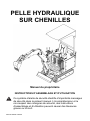
CRAWLER EXCAVATOR
Owner’s Manual
ASSEMBLY AND OPERATING INSTRUCTIONS
This safety alert symbol identifies important safety messages in
this manual. Failure to understand and follow safety, assembly and
operating instructions could result in serious injury or death.
REV12122023 TS8100

- 2 -
Table of Contents
Important Safety Information......................................................................... 3-4
Controls and Features Identification……………………………………………….5
Assembly Instructions.................................................................................. 6-10
Operating Instructions..................................................................................... 11
Maintenance Instructions…………...................................................................12
Troubleshooting………….................................................................................13
Specifications.................................................................................................. 14
Drawing and Parts List............................................................................... 15-24
Limited Warranty............................................................................................. 25

- 3 -
WARNING: Read and understand all instructions and safety information in this manual and on safety
decals before assembling or operating the crawler excavator. Failure to understand and follow all
instructions and safety information may result in serious injury or death. Persons who have not
read the manual should never operate the crawler excavator. A crawler excavator can be dangerous
when assembled and/or used improperly. Do not operate the crawler excavator if you have any
questions concerning safe operation. Please call the technical support department for answers to
any questions.
WARNING: This product can expose you to chemicals including lead and lead compounds which are
known to the State of California to cause cancer and birth defects or other reproductive harm. For
more information, go to www.P65Warnings.ca.gov
INTENDED USE
NEVER use the crawler excavator for any purposes other than trenching. The crawler excavator is designed for
trenching. Using the crawler excavator for any other purpose can result in serious injury or death and may void the
warranty.
PERSONAL PROTECTIVE EQUIPMENT
BEFORE operating the crawler excavator always be sure to put on appropriate safety gear, including eye protection
(goggles), steel-toed shoes and tight-fitting gloves (without loose cuffs or draw strings). Also, the use of proper hearing
protection (headphones) is required when operating the crawler excavator.
GENERAL SAFETY
* Read the Owner’s Manual completely before attempting to use this excavator.
* Do not allow anyone to operate your excavator who has not read the Operator’s Manual or has not been instructed on
the safe operation of the excavator.
* Never allow children or untrained adults to operate this machine.
* Never allow anyone to ride on the excavator while driving.
* Never transport cargo on the excavator.
* High fluid pressures are developed in hydraulic excavators. Pressurized fluid escaping though a pin hole opening can
puncture skin and cause severe blood poisoning. Therefore, the following instructions should be followed at all times.
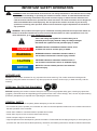
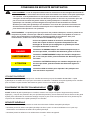
DANGER
WARNING
CAUTION
IMPORTANT SAFETY INFORMATION
DANGER indicates a hazardous situation which, if not
avoided, will result in serious injury or death.
WARNING indicates a hazardous situation which, if
not avoided, could result in serious injury or death.
CAUTION indicates a hazardous situation which, if
not avoided, could result in minor or moderate injury.
NOTICE is used to address practices not related to
personal injury.
This is the safety alert symbol. It is used to alert you to
potential personal injury hazards. Obey all safety messages
that follow this symbol to avoid possible injury or death.
NOTICE

- 4 -
(a) Do not operate the unit with frayed, kinked, cracked or damaged hoses, fitting, or tubing.
(b) Stop the engine and relieve hydraulic system pressure before leaving the excavator unattended or servicing
fittings, hoses, tubing, or other system components.
(c) Do not adjust the pressure settings of the pump or control valve.
(d) Do not check for leaks with your hand. Leaks can be located by passing cardboard or wood over the suspected
area. Look for discoloration. If injured by escaping fluid, see a doctor at once. Serious infection or reaction can
develop if proper medical treatment is not administered immediately.
* Keep the operator zone and adjacent area clear for safe trenching. Use extreme caution when operating near
structures, utility line, or when other workers are present. Call utilities before you dig. Don’t straddle trench with
excavator. Move excavator backward and away from the trench as you dig.
* If your excavator is intended for use near any unimproved forest, brush, or grass covered land, the engine exhaust
should be equipped with a spark arrestor. Make sure you comply with applicable local, state, and federal codes. Take
appropriate fire-fighting equipment with you.
* Excavator s should be only used for trenching. Do not use for other purpose.
* Never alter the excavator or any part of its manufactured design.
PREPARATION
* Contact municipalities and utilities to locate buried lines before digging. Do not dig until you have fully investigated the
area. Use extreme caution when overhead or buried utility lines are present.
* Be thoroughly familiar with all controls and with the proper use of the equipment.
a) Always wear safety shoes or heavy boots
b) Always wear safety glasses or goggles and approved safety headgear when operating the machine.
c) Never wear jewelry or loose clothing that might become entangled in moving or rotating parts of the machine.
d) Always wear protective hearing devices when operating the excavator. Continued exposure to loud machinery
can cause hearing loss.
* Make sure the excavator is on a level surface with no more than 10°incline. Block the machine as required to prevent
unintended movement. Do not operate near soft-shouldered inclines that may not provide adequate support.
* Always operate the excavator from the operator seat with hands positioned near valve controls and feet flat on the
area provided.
* Handle fuel with care; it is highly flammable.
a) Use an approved fuel container.
b) Never add fuel to a running or hot engine.
c)Fill fuel tank outdoors with extreme care. Never fill fuel tank indoors.
d)Replace gasoline cap securely and clean up spilled fuel.
* Only use the excavator in daylight or adequate artificial light.

- 5 -
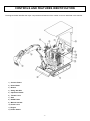
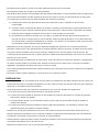
The diagram below identifies the major components and features of the crawler excavator described in this manual.
1) Chassis Frame
2) Dozer Blade
3) Bucket
4) Swing Arm Kits
5) Operation Handle
6) Throttle Lever
7) Seat
8) ROPS Frame
9) Manual Canister
10) Choke Lever
11) Engine
12) Power Switch
CONTROLS AND FEATURES IDENTIFICATION

- 6 -
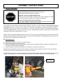
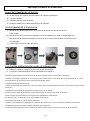
A) General information
The crawler excavator is almost ready for use upon delivery. However, it is still necessary to add engine oil, gasoline
and hydraulic oil. Then conduct a visual check of the connections (hydraulics, mechanical parts, tighten screws, if
necessary). Only start the machine if a person is in the seat. Read and ensure you understand the following
instructions before planning your first use of the excavator. Wear adequate protective clothing such as safety shoes
and safety gloves when working with the excavator.
Read the entire instructions BEFORE! using the excavator for the first time and familiarize yourself with the individual
operation steps! During the initial operation, slowly move the levers and develop an understanding of the machine. The
main boom can be controlled via a throttle valve.
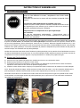
B) Add engine oil
a) Make sure the crawler excavator is on a level surface.
b) Remove the dipstick to check the oil level.
c) Refer to the separate owner’s engine manual to determine the necessary quantity of engine oil; add engine oil to
the proper level and replace the dipstick.
d) Check the engine oil level daily and add oil as necessary to maintain the proper level.
NOTICE: During the break-in period check the engine oil level often. When initially using the excavator the operator
should check the engine oil level frequently to ensure proper function.
DO NOT attempt to crank or start the engine before it has been properly filled with the recommended type and amount
of engine oil. Damage to the excavator resulting from a failure to follow these instructions will void the warranty.
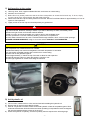
Engine Shipped Without Oil.
Before starting engine, fill with SAE 10W-30 motor oil.
See engine manual for engine oil capacity.
Hydraulic Oil Tank is Shipped Without Oil.
Check the oil level from the oil meter at the side of machine to make
sure the oil level is in middle of the oil meter for operation.
Inspect all Crawler Excavator Components.
If you have damaged components: Contact the freight company that
delivered the crawler excavator and file a claim.
ASSEMBLY INSTRUCTIONS
Maximum

- 7 -
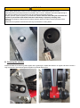
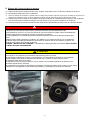
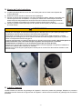
C) Add gasoline to the engine
a) Use only clean, fresh, regular unleaded fuel with a minimum 87 octane rating.
b) DO NOT mix oil with fuel.
c) Before fill in fuel, please position the seat in the front-most position to access the fuel tank cap. To do so, simply
move the lever to the right and push the seat toward the front.
d) Remove the fuel tank cap and slowly add fuel to the tank. DO NOT overfill and allow for approximately a ¼ inch of
space for fuel expansion.
e) Tightly screw on the fuel cap and clean/wipe away any spilled fuel.
DANGER
Engine exhaust contains carbon monoxide, a colorless, odorless, poison gas. Breathing carbon monoxide
may cause nausea, dizziness, fainting or death. If you start to feel dizzy or weak, immediately cease
operation and get to fresh air and seek medical attention.
Crawler excavator should be operated only outdoors and in well-ventilated areas.
DO NOT operate the excavator inside any building, enclosure or compartment.
DO NOT allow exhaust fumes to enter a confined area through windows, doors, vents or other openings.
DANGER CARBON MONOXIDE, using an excavator indoors CAN KILL YOU IN MINUTES.
CAUTION
Fuel and fuel vapors are highly flammable and extremely explosive.
Fire or explosion can cause severe burns or death.
Unintentional startup can result in entanglement, traumatic amputation or laceration.
Only use regular unleaded gasoline with a minimum 87 octane rating.
DO NOT mix oil and gasoline together.
Fill tank approximately ¼” below the top of the tank to allow for fuel expansion.
DO NOT fill fuel tank indoors or when the engine is running or hot.
DO NOT light cigarettes or smoke when filling the fuel tank.
D) Add hydraulic oil
a) The excavator needs to be on a flat, level surface before adding the hydraulic oil.
b) Remove the oil cap from the hydraulic oil tank.
c) Add 19L of hydraulic oil AW32, AW46 & universal hydraulic oil are all acceptable types of fluid.
Automatic transmission fluid should be used when operating in temperatures below 32 degrees
(all units are tested and have excess oil in the ram).
d) Check the hydraulic oil quantity, and the oil quantity need to expose to the oil level gauge.

- 8 -
WARNING
DO NOT remove the hydraulic oil cap when the engine is running or hot. Hot oil can escape causing severe
burns. Always allow the excavator to cool completely before removing the hydraulic oil cap.
High fluid pressure and temperatures are created in the excavator. Hydraulic fluid will escape through a
pin-size hole opening and can puncture skin and cause severe blood poisoning.
Inspect hydraulic system regularly for possible leaks. Never check for leaks with your hand while the
system is pressurized. Seek medical attention immediately if injured by escaping fluid.
Make sure all fittings are tight and secure before applying pressure. Relieve system pressure before
servicing.
Make sure the hydraulic hoses do not touch any hot surfaces or cutting areas.
E) Greasing the machine
Please lubricate the machine's grease nipples with a grease gun. Repeat this behavior in regular intervals to ensure a
long machine life. Also lubricate grease nipples on potential attachments.

- 9 -
F) Dozer blade
The dozer blade can be moved up or down as necessary. If you dig in a place for a long time, it is recommended to
keep the blade lowered.
G) Additional connection for hydraulic attachments
In addition, this excavator is equipped with two hydraulic connectors. They can be used to connect for additional
attachments.
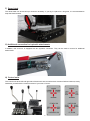
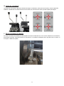
H) Control units
The control units at the left and right side of the driver’s seat, as well as their functions. Before initial use, slowly
familiarize yourself with the control functions of your new excavator.

- 10 -
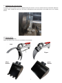
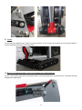
I) Adjusting the track tension
If needed, the track tension can be re-adjusted using the screws. To do so, loosen the lock nut and then adjust the
tension. Then, re-attach the lock nut. The track is manufactured with small holes in the middle; this is not a quality
defect!
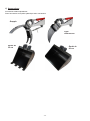
J) Accessories:
Accessories sell separately.
Attach accessory on the excavator according to your purpose.
Grab
Ripper
35cm
Bucket
60cm
Bucket

- 11 -
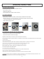
BEFORE STARTING WORK
a) Check the oil level in the engine and hydraulic reservoir.
b) Lubricate the machine.
c) Move to the work zone.
d) Check tightness and condition of parts, check fuel.
TO START WORKING
a) Keep away at a distance of at least 15m from people, animals and all other objects.
b) Hold the top button to move the throttle lever in the middle of the gear; Gently Pull choke
lever and turn ignition key to start; Press choke lever.
c) Begin digging using the levers.
AT THE END OF THE EXCAVATOR OPERATIONS
a) Close the arm on itself, turn to the transport position.
b) Turn off the machine, close the fuel supply.
Regularly maintain safety accessories. (Check maintenance instructions)
Do not use the excavator under the influence of medication, alcohol, drugs or any substances that can cause any kind
of disorientation.
Work only during the day.
The machine must not be used if there are people, especially children or animals in the work zone.
The machine must be operated by trained personnel and after reading this manual.
Before turning the machine on, check the functions of the safety devices.
Before operating the machine, make sure the stabilizer blade is lowered.
Do not move, stop or work under the arm.
Do not work under or near power lines.
Do not use the machine to transport, lift people or for any other unforeseen uses.
Never exceed the usage limits set by the manufacturer.
Never leave the machine unattended when the engine is running or the key is inserted.
CAUTION: Using the machine is forbidden to children and people who are not familiar with these instructions. Local
regulations may prohibit the use of the machine depending on the age.
OPERATING INSTRUCTIONS

- 12 -
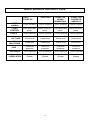
FIRST
START-UP
EVERYDAY
EVERY 150
HOURS
OR MONTHLY
EVERY 1200
HOURS OR
ANNUALLY
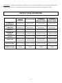
SAFETY
LABELS
Check condition Check condition Check condition Check condition
LEVER
CONTROL
Check automatic
return
Check automatic
return
Check automatic
return
Check automatic
return
HOSES Check tightness Check tightness Check tightness Check tightness
OIL TANK Check level Check level Check level Check level
OIL
MULTIPLIER
Check level Check level Check level Check level
PINS Check for
presence
Check for
presence
Check for
presence
Check for
presence
HARDWARE Check tightness Check tightness Check tightness Check tightness
LUBRICATION
Grease Grease Grease Grease
MAINTENANCE INSTRUCTIONS

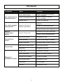
- 13 -
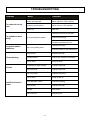
Problem Cause Solution
The controls do not
work
Hoses unconnected Move switch to “ON” position
Hydraulic pump broken Move valve to “ON” position
Lack of oil Add fuel
The cylinders move
jerkily Air in the hydraulic system
Check the oil level in the tank
Check hose fittings
Work each cylinder for a few
minutes to push the air out
Loose arm and/or
stabilizers Worn out cylinder joints
Replace the seals
Check the wear of the
distributors
Oil overheating
Dirty oil filter Replace the filter
Crushed hoses Check and replace if necessary
Low oil level Fill up to level
Oil leak
Couplings not tight enough Tighten couplings
Worn out joints Replace the joints
Insufficient bucket
power
Worn out pump Replace the pump
Low oil level Level up the oil
Badly adjusted valves Check the setting
Dirty oil filter Replace the filter
Oil leak See above
Worn out joint Replace joint
TROUBLESHOOTING

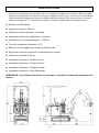
- 14 -
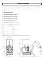
This Crawler Excavator is a real compact multifunctional machine. It’s small, powerful and
versatile. At a compact width of 822 mm you can even use this micro excavator in difficult to
access areas. It has a powerful 13-15 HP petrol engine to power the high performance hydraulic
system.
360 Degree Rotation
Working Width: 822mm
Maximum Gradeability: 15 Degree
Platform Rotation Speed: 6.5r/min
Maximum Digger Depth: 1456mm
Maximum Digging Strength: 2.2T
Separate Oil Tank to avoid oil leaking.
Seat with Safety Belt and Gravity Switch
Comes with 20CM Bucket
Optional Accessory: 60CM Bucket
Optional Accessory: 35CM Bucket
Optional Accessory: Log Grapple
Optional Accessory: Ripper
NOTE: For Engine Details Refer to the Engine Owner’s Manual.
SPECIFICATIONS

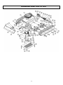
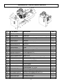
- 15 -
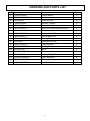
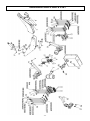
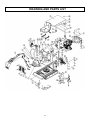
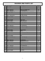
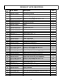
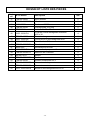
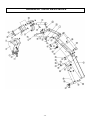
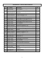
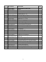
DRAWING AND PARTS LIST

- 16 -
Ref#
Drawing No.
Description
Qty.
1
TS8100-12000
Swing Bearing
1
2 TS8100-11000 Chassis Weldment 1
3
TS8100-00059-DX
Adjust Kit
2
4 9101-12110-DX8.8Q Hex Bolt M12x110 4
6
TS8100-00064-DX
Angle Connector
2
7 TS600-00009-DX O Lock Pin 2
8 TS8100-18000 Dozer Blade 1
9
TS8100-19000
Cylinder
1
10 TS8100-00062-DX Pin Ø20x87 2
11
TS8100-00061-DX
Front Axle
1
12 TS8100-00052-DX Long Connector 3
13
9901-6x1.5
O Ring Ø6x1.5
6
14 TS8100-00053-DX Short Connector 6
15
TS8100-00060-DX
Shaft
1
16 TS8100-00066 Hydraulic Tube 2
17 TS8100-00054 Sealing Ring 12
18 TS8100-14000 Hydraulic Distributor 1
19 9306-12000-DX Lock Washer Ø12 32
20
9201-12000-DX
Hex Nut M12
6
21 9101-08025-DX8.8 Hex Bolt M8x25 6
22
9301-12000-DX
Flat Washer Ø12
8
23 9101-12025-DX8.8 Hex Bolt M12x25 6
24
TS8100-00058
Bottom Cover Plate
1
25 TS8100-00055-DX Mounting Sleeve 2
26
TS8100-00056
Adapter Connection Plate
1
27 9101-12040-DX8.8 Hex Bolt M12x40 20
28 TS8100-00050 Hydraulic Tube 2
29
9901-8x1.8
O Ring Ø8x1.8
4
30 TS8100-00051 Hydraulic Tube 2
31
9302-12000-DX
Large Flat Washer Ø12
8
32 TS8100-00043 Side Plate 2
33
TS8100-00046
Rubber Track
2
34 9101-08040-DX Inner Hex Socket Screw M8x40 2
35
9306-08000-DX
Lock Washer Ø8
8
36 TS8100-00044-DX Plug 2
DRAWING AND PARTS LIST

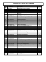
- 17 -
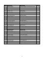
Ref#
Drawing No.
Description
Qty.
37 TS8100-09000 Driving Wheel 2
38 TS8100-00057-DX Sleeve 8
39
9306-80205
Bearing 80205
16
40 TS8100-00045 Flat Key 10x8/20 2
41
TB50X65X8
Oil Seal 50x65x8
2
42 9105-12030-FH Inner Hex Socket Screw M12x30 4
43
TS8100-10000
Burden Wheel
8
44 9206-10000-DX Hex Lock Nut M10 4
45
9306-10000-FH
Lock Washer Ø10
4
46 TS8100-00047-DX Bearing Block 2
47 9609-2207 Bearing NF207EM 2
48
9309-07200-FH
Circlip for Hole
2
49 TS8100-00048-FH Bearing Sleeve 2
50
4R16N1 5/31
Motor
2
51 TS8100-00049-DX Bolt 4
52
TS8100-00030
Sealing Ring 23.5
4
53 TS8100-00029-DX Pipe Connector 4
54
TS8100-00063-DX
Middle Connector
3
55 9101-12050-DX8.8 Hex Bolt M12x50 2
DRAWING AND PARTS LIST

- 18 -
DRAWING AND PARTS LIST

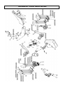
- 19 -
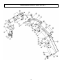
Ref#
Drawing No.
Description
Qty.
1 TS8100-00068 Bucket Teeth 3
2 9206-10000-DX Nylon Lock Nut M10 10
3
9104-10030-DX12.9
Inner Hex Socket Screw M10x30
6
4 TS8100-23000 Bucket A 1
5
TS8100-00069-DX
Hitch Pin 20-124
2
6 TS8100-24000-DX Pin Seat 20-132 2
7
TS8100-22000
Quickt Hitch Weldment
1
8 TS8100-25000 Moon Bracket Weldment 1
9
TS8100-00067-DX
Hitch Pin 20-100
1
10 TS8100-26000 Moon Bracket Weldment 1
11 TS8100-27000 Bucket Cylinder 1
12
TS8100-21000
Arm Weldment
1
13 TS8100-20000-DX Pin Seat 25-105 1
14
TS8100-30000-DX
Pin Seat 25-145
1
15 9105-08035-FH Inner Hex Socket Screw M8x35 2
16
TS8100-36000
Clip
2
17 TS8100-00064-DX 90°Angle Connector 4
18
TS8100-17000-DX
Pin Seat 25-135
2
19 9301-06000-DX Flat Washer Ø6 9
20 9306-06000-DX Lock Washer Ø6 9
21 9101-06016-DX Bolt M6x16 9
22 TS600-00009-DX O Lock Pin 12
23
TS8100-16000
Boom Weldment
1
24 TS8100-15000 Boom Cylinder 2
25
TS8100-13000-DX
Pin Seat 25-153
2
26 TS8100-00076 Throttle Gasket 1
27
TS8100-00073-DX
Impedance Screw
2
28 TS8100-00065-DX Angle Connector 2
29
TS8100-29000
Plate
1
30 9112-10030-FH8.8 Inner Hex Socket Screw M10x30 4
31 9306-08000-DX Lock Washer Ø8 2
32
9701-06000
Oil Cup
9
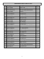
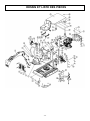
DRAWING AND PARTS LIST

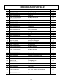
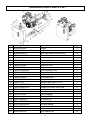
- 20 -
Ref#
Drawing No.
Description
Qty.
1
XR2100-420CC
Engine
1
2
LGS13-10000
Air Filter
1
3
9108-06020-FH
Inner Hex Socket Screw M6x20
12
4
TS8100-00001-DX
Cover Plate
1
5
LSP25-00021
Pad
2
6
N900-00008
Oil Level Gauge
1
7
LSP25-00010-DX
Plug
1
8
TS8100-07000
Hydraulic Tank
1
9
LSP25-00022
Filter
1
10
TS8100-05000-DX
Filter Mounting Plate
1
11
TS8100-00009-DX
Suction Connector
4
12
TS8100-00008-DX
Three Links 1/2
1
13
TS8100-00038
Oil Suction Pipe
2
14
LSE12D-00004-BXG
Clamp 21-32
4
15
CBW3.5-3.5
Double Gear Pump 3.5+3.5
1
16
9101-10035-DX8.8Q
Hex Bolt M10x35
2
17
TS8100-00013-DX
Straight Connector M18-G3/8
2
18
TS8100-00014
Sealing Ring
2
19
/
Flat Key
1
20
TS8100-07000
Plum Coupling
1
21
/
Flat Key 7x7x40
1
22
9201-10000-DX
Hex Nut M10
2
23
TS8100-06000-DY
Gear Pump Stand
1
24
9101-08030-DX8.8
Hex Bolt M8x30
4
25
9306-08000-DX
Lock Washer Ø8
4
26
9306-10000-DX
Lock Washer Ø10
2
27
9306-06000-DX
Lock Washer Ø6
12
DRAWING AND PARTS LIST
La page charge ...
La page charge ...
La page charge ...
La page charge ...
La page charge ...
La page charge ...
La page charge ...
La page charge ...
La page charge ...
La page charge ...
La page charge ...
La page charge ...
La page charge ...
La page charge ...
La page charge ...
La page charge ...
La page charge ...
La page charge ...
La page charge ...
La page charge ...
La page charge ...
La page charge ...
La page charge ...
La page charge ...
La page charge ...
La page charge ...
La page charge ...
La page charge ...
La page charge ...
La page charge ...
La page charge ...
La page charge ...
-
 1
1
-
 2
2
-
 3
3
-
 4
4
-
 5
5
-
 6
6
-
 7
7
-
 8
8
-
 9
9
-
 10
10
-
 11
11
-
 12
12
-
 13
13
-
 14
14
-
 15
15
-
 16
16
-
 17
17
-
 18
18
-
 19
19
-
 20
20
-
 21
21
-
 22
22
-
 23
23
-
 24
24
-
 25
25
-
 26
26
-
 27
27
-
 28
28
-
 29
29
-
 30
30
-
 31
31
-
 32
32
-
 33
33
-
 34
34
-
 35
35
-
 36
36
-
 37
37
-
 38
38
-
 39
39
-
 40
40
-
 41
41
-
 42
42
-
 43
43
-
 44
44
-
 45
45
-
 46
46
-
 47
47
-
 48
48
-
 49
49
-
 50
50
-
 51
51
-
 52
52


Red Rock 9208604 Le manuel du propriétaire
- Taper
- Le manuel du propriétaire
dans d''autres langues
- English: Red Rock 9208604 Owner's manual