Deckorators LED Recessed Riser Light Kit Guide d'installation
- Taper
- Guide d'installation

Step 2
Drill Holes and Install Light
2.1 Layout the locaon of the light(s). To prevent
spling, do not install within 1/2” of the edge
of the light and the edge the deck board.
2.2 Use a 7/8” Diameter Bi-Metal Hole Saw for aluminum posts, or a 7/8” Forstner
Bit on nonmetal posts to bore a hole through the deck board. NOTE: Ensure the
diameter is no larger than 7/8”, as the light requires a tight fit for ideal funcon.
It is recommended to ensure the bit will provide a ght enough hole on a scrap
piece of post or deck board before drilling. Run the male end of the harness from
Step 1.2 through the back of the hole.
2.3 Plug the male connector of the harness from Step 2.2 into the female connector
aached to the light. Press firmly unl the connecon is fully engaged.
2.4 Connecon is fully engaged when there is minimal gap between the male and
female connector.
2.5 Place the Recessed Riser Light into the hole drilled in Step 2.2, inserng the
connected harnesses and wire first. Firmly press the Riser Light and cover into
the deck board unl the assembly is fully seated.
2.6 The Recessed Riser light will now be illuminated if the transformer is on and
providing power.
*If the drilled hole is too loose to hold the light snugly, a small amount of silicone caulk on the inside of the hole is
recommended to hold the light in place.
Pre -
Installation
Notes
Do not cut any wires. Extra wire length can be coiled up.
If using insulated wire staples to hold the wires in place, be
sure not to pierce or crush the wires.
Wiring harness should have enough slack so light fixture
can be removed if future replacement is needed.
Step 1
Prepare the Transformer and Wiring Harness
1.1 Follow instrucons provided with the
transformer.
1.2 Follow instrucons for the wiring harnesses so
there is a male connector located at each
locaon that will have a light installed.
Recessed Riser Light
INST#: XISFRRL-REV 6-19
Components
Recessed Riser
Light With Cover
7/8” Diameter
Forstner Bit or Bi-
Metal Hole Saw
Power
Drill
Le
minimum
1/2 po de
bord
Percer
par
Conseil
KIT DE LUMIÈRES DE CONTREMARCHE À DEL
INSTRUCCIONES DE INSTALACIÓN
Étape 1: Préparez le transformateur: suivez les instructions fournies avec le
transformateur.
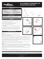
Étape 2: Disposez l'emplacement de la ou des lumières. Pour éviter le
fendillement, n'installez pas à moins de 1/2 po du bord du luminaire et du
bord de la planche de terrasse (fig. 1).
Instructions d'installation
Step 2
Drill Holes and Install Light
2.1 Layout the locaon of the light(s). To prevent
spling, do not install within 1/2” of the edge
of the light and the edge the deck board.
2.2 Use a 7/8” Diameter Bi-Metal Hole Saw for aluminum posts, or a 7/8” Forstner
Bit on nonmetal posts to bore a hole through the deck board. NOTE: Ensure the
diameter is no larger than 7/8”, as the light requires a tight fit for ideal funcon.
It is recommended to ensure the bit will provide a ght enough hole on a scrap
piece of post or deck board before drilling. Run the male end of the harness from
Step 1.2 through the back of the hole.
2.3 Plug the male connector of the harness from Step 2.2 into the female connector
aached to the light. Press firmly unl the connecon is fully engaged.
2.4 Connecon is fully engaged when there is minimal gap between the male and
female connector.
2.5 Place the Recessed Riser Light into the hole drilled in Step 2.2, inserng the
connected harnesses and wire first. Firmly press the Riser Light and cover into
the deck board unl the assembly is fully seated.
2.6 The Recessed Riser light will now be illuminated if the transformer is on and
providing power.
*If the drilled hole is too loose to hold the light snugly, a small amount of silicone caulk on the inside of the hole is
recommended to hold the light in place.
Pre -
Installation
Notes
Do not cut any wires. Extra wire length can be coiled up.
If using insulated wire staples to hold the wires in place, be
sure not to pierce or crush the wires.
Wiring harness should have enough slack so light fixture
can be removed if future replacement is needed.
Step 1
Prepare the Transformer and Wiring Harness
1.1 Follow instrucons provided with the
transformer.
1.2 Follow instrucons for the wiring harnesses so
there is a male connector located at each
locaon that will have a light installed.
Recessed Riser Light
INST#: XISFRRL-REV 6-19
Components
Recessed Riser
Light With Cover
7/8” Diameter
Forstner Bit or Bi-
Metal Hole Saw
Power
Drill
Le
minimum
1/2 po de
bord
Percer
par
Conseil
Contenu du kit
Préparation
Outils nécessaires
• Ne coupez aucun fil. Toute longueur de fil supplémentaire peut être enroulée.
• Si vous utilisez des agrafes isolées pour maintenir les fils en place, assurez-
vous de ne pas percer ou écraser les fils.
• Le faisceau de câbles doit avoir suffisamment de jeu pour que le luminaire
puisse être retiré si un remplacement futur est nécessaire.
• Ne regardez pas directement dans la lumière.
• À utiliser uniquement avec un système d'éclairage paysager extérieur basse
tension de 12 volts.
• Pendant l'installation, il est recommandé de couvrir temporairement la
cellule photoélectrique du transformateur avec du ruban adhésif foncé afin
que les lumières s'allument lorsque vous les branchez. Cela aidera à vérifier
tout problème pendant l'installation. Retirez le ruban lorsque vous avez
terminé.
fig. 1 fig. 2
fig. 3 fig. 4
fig. 5
LES DIAGRAMMES ET LES INSTRUCTIONS DE CETTE BROCHURE SONT À DES FINS D'ILLUSTRATION UNIQUEMENT ET NE SONT PAS DESTINÉS À REMPLACER UN PROFESSIONNEL AGRÉÉ. TOUTE CONSTRUCTION OU UTILISATION DU PRODUIT DOIT ÊTRE
CONFORME À TOUS LES CODES DE ZONAGE ET/OU DE CONSTRUCTION LOCAUX. LE CONSOMMATEUR ASSUME TOUS LES RISQUES ET RESPONSABILITÉS ASSOCIÉS À LA CONSTRUCTION OU À L'UTILISATION DE CE PRODUIT. LE CONSOMMATEUR OU
L'ENTREPRENEUR DOIT PRENDRE TOUTES LES MESURES NÉCESSAIRES POUR ASSURER LA SÉCURITÉ DE TOUTES LES PERSONNES IMPLIQUÉES DANS LE PROJET, Y COMPRIS, MAIS SANS S'Y LIMITER, LE PORT DE L'ÉQUIPEMENT DE SÉCURITÉ APPROPRIÉ.
À L'EXCEPTION DE CE QUI EST CONTENU DANS LA GARANTIE LIMITÉE ÉCRITE, LE GARANT NE FOURNIT AUCUNE AUTRE GARANTIE, EXPLICITE OU IMPLICITE, ET NE SERA PAS RESPONSABLE DES DOMMAGES, Y COMPRIS LES DOMMAGES INDIRECTS.
©2021 UFP Retail Solutions, LLC. Deckorators est une marque déposée de UFP Industries, Inc. aux États-Unis. Tous droits réservés.
68956 U.S. Highway 131, White Pigeon, MI 49099
13865 12/21
www.deckorators.com
Contremarche encastrée
Lumière avec couvercle
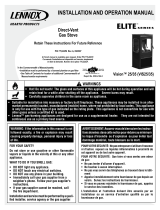
Étape 3: Utilisez une scie-cloche bimétallique de 7/8 po de diamètre pour les poteaux en aluminium ou une mèche
Forstner de 7/8 po sur les poteaux et planches non métalliques pour percer un trou à fond plat (fig. 2). Remarque :
assurez-vous que le diamètre n'est pas supérieur à 7/8", car la lumière nécessite un ajustement serré pour une fonction
idéale. Il est recommandé de s'assurer que le foret fournira un trou suffisamment serré sur un morceau de poteau ou
de planche de terrasse avant de percer. Déconnectez l'extrémité mâle du harnais de l'extrémité femelle de la lumière.
Insérez l'extrémité mâle du harnais à travers l'arrière du trou percé.
Étape 4: Branchez le connecteur mâle du faisceau de l'étape 3 dans le connecteur femelle attaché à la lumière (fig.
3). Appuyez fermement jusqu'à ce que la connexion soit complètement engagée.
Étape 5: La connexion est complètement engagée lorsqu'il y a un écart minimal entre le connecteur mâle et
femelle (fig. 4).
Étape 6: Un choix de couvercles de lumière de colonne montante noirs ou blancs est fourni dans le kit. Placer le
couvercle sur la colonne montante. Placez la lumière de la colonne montante avec le couvercle dans le trou percé
à l'étape 3, en insérant d'abord les faisceaux connectés et le fil. Enfoncez fermement le Riser Light et le couvercle
dans la planche de terrasse jusqu'à ce que l'ensemble soit complètement en place (fig. 5).
Étape 7: La lumière de la colonne montante encastrée s'allumera maintenant si le transformateur est allumé et
fournit de l'énergie.
Remarque : si le trou percé est trop lâche pour maintenir la lumière confortablement, une petite quantité de mastic de
silicone à l'intérieur du trou est recommandée pour maintenir la lumière en place.
Un kit d'éclairage pour colonne montante contient:
Harnais 2 sorties
Séparateur
Trousse de 8pièces:
• 7 - Séparateurs
• 8 - 5 pi Harnais
• 8 - Lumières LED Riser
• 8 - Bagues De Garniture Blanches
• 8 - Bagues de finition noires
Trousse de 2 pièces :
• 2 - Séparateurs
• 2 - 5 pi Harnais
• 2 - Lumières LED Riser
• 2 - Bagues De Garniture Blanches
• 2 - Bagues de finition noires
• Perceuse électrique
• Forstner Bit ou scie-cloche bimétallique de 1-1/4 po de diamètre
Step 2
Drill Holes and Install Light
2.1 Layout the locaon of the light(s). To prevent
spling, do not install within 1/2” of the edge
of the light and the edge the deck board.
2.2 Use a 7/8” Diameter Bi-Metal Hole Saw for aluminum posts, or a 7/8” Forstner
Bit on nonmetal posts to bore a hole through the deck board. NOTE: Ensure the
diameter is no larger than 7/8”, as the light requires a tight fit for ideal funcon.
It is recommended to ensure the bit will provide a ght enough hole on a scrap
piece of post or deck board before drilling. Run the male end of the harness from
Step 1.2 through the back of the hole.
2.3 Plug the male connector of the harness from Step 2.2 into the female connector
aached to the light. Press firmly unl the connecon is fully engaged.
2.4 Connecon is fully engaged when there is minimal gap between the male and
female connector.
2.5 Place the Recessed Riser Light into the hole drilled in Step 2.2, inserng the
connected harnesses and wire first. Firmly press the Riser Light and cover into
the deck board unl the assembly is fully seated.
2.6 The Recessed Riser light will now be illuminated if the transformer is on and
providing power.
*If the drilled hole is too loose to hold the light snugly, a small amount of silicone caulk on the inside of the hole is
recommended to hold the light in place.
Pre -
Installation
Notes
Do not cut any wires. Extra wire length can be coiled up.
If using insulated wire staples to hold the wires in place, be
sure not to pierce or crush the wires.
Wiring harness should have enough slack so light fixture
can be removed if future replacement is needed.
Step 1
Prepare the Transformer and Wiring Harness
1.1 Follow instrucons provided with the
transformer.
1.2 Follow instrucons for the wiring harnesses so
there is a male connector located at each
locaon that will have a light installed.
Recessed Riser Light
INST#: XISFRRL-REV 6-19
Components
Recessed Riser
Light With Cover
7/8” Diameter
Forstner Bit or Bi-
Metal Hole Saw
Power
Drill
Le
minimum
1/2 po de
bord
Percer
par
Conseil
Wiring Harness and Splitters
Components
1.1
1.3
2.1
2.2
2.3
2.4
2.5
Pre -
Installation
Notes
Do not cut any wires. Any extra wire length can be coiled
up.
If using insulated wire staples to hold the wires in place,
be sure not to pierce or crush the wires.
During installaon, it is recommended that you
temporarily cover the photocell on the transformer with
dark tape so the lights will be on when you plug them in.
This will help check for any issues during installaon.
Remove tape when done.
Harness
1.1 The Harness is used to extend power from the
transformer to each individual light or splier.
The Harness has a male and female end.
1.2 Harnesses can be plugged into each other to
extend length if needed.
1.3 The Harness can be run underneath the deck
(above ground) and/or inside the post/railing
where it is hidden from view.
1.4 If needed, the connectors can fit through a 1/2”
hole.
5 Output Splitter
2.1 The 5 Output Splier is used to evenly distribute
power from 1 input to 5 outputs.
2.2 Plug the male connector from a harness into the
female input connector of the 5 Output Splier.
Press firmly unl the connecon is fully engaged.
2.3 Connecon is fully engaged when there is minimal
gap between the male harness connector and the
female input connector.
2.4 Plug the female connector from a harness or a light
into one of the male output connectors. Repeat for
each output connector that is needed.
2.5 If there are any unused output connectors, an end
cap (2 included) must be used to seal the output
connector. Any unused end caps can be saved or
discarded. If there are more than 2 unused output
connectors, a 2 Output Splier (see below) should
be used.
2.6 The 5 Output Splier can be secured using (2) #2
Stainless Steel Screws (not supplied).
2 Output Splitter
3.1 The 2 Output Splier is used to evenly distribute
power from 1 input to 2 outputs.
3.2 Plug the male connector from a harness into the
female input connector of the 2 Output Splier.
Press firmly unl the connecon is fully engaged.
(See Step 2.3)
3.3 Plug the female connector from a harness or a light
into one of the male output connectors. Repeat for
the other output connector.
Harness
(Various Lengths)
1.2
5 Output Splier
(2 End Caps Included)
2 Output Splier
1/2”
3.2
3.3
-
 1
1

Deckorators LED Recessed Riser Light Kit Guide d'installation
- Taper
- Guide d'installation
dans d''autres langues
Documents connexes
Autres documents
-
 Lennox Hearth Gas Stove Manuel utilisateur
-
Harris XL-185M Guide d'installation
-
Lincoln Electric Wire-Matic 250 Mode d'emploi
-
NAPOLEON BGD36CF Le manuel du propriétaire
-
Pride Outlander Series Le manuel du propriétaire
-
AOG Portable Grill L-Series Manuel utilisateur
-
-
NAPOLEON Bayfield GDS25N-1 Le manuel du propriétaire
-
Volkswagen 1K0 054 630 B Installation Instructions Manual
-
 Farm Innovators 9169566 Le manuel du propriétaire

