Schneider Electric PowerPact H L-Frame Circuit Breaker Mode d'emploi
- Taper
- Mode d'emploi

PowerPact™ H-, J-, or L-Frame Circuit Breaker with
Micrologic™ 5/6 Retrofit Instructions
Installation onto an I-Line™ Panelboard Rated 480 Vac Maximum
Instrucciones de actualización de los interruptores
automáticos PowerPact™ marco H, J o L con unidad de
disparo Micrologic™ 5/6
Instalación en un tablero I-Line™ de 480 V~ como máximo
Directives de modernisation pour disjoncteurs
PowerPactMC à châssis H, J ou L avec déclencheur
Micrologic 5/6
Installation sur un panneau de distribution I-LineMC à valeur nominale
maximale de 480 Vca
Instruction Bulletin
Boletín de instrucciones
Directives d'utilisation
80043-801-01
03/2013
Retain for Future Use. /
Conservar para uso futuro. /
À conserver pour usage ultérieur.
Restricted to Schneider Electric Personnel
Restringido al personal de Schneider Electric
Limité au personnel de Schneider Electric
™


© 2013 Schneider Electric All Rights Reserved / Reservados todos los derechos / Tous droits réservés 3
80043-801-01 Table of Contents
03/2013 Contenido
Table des matières
ENGLISHESPAÑOLFRANÇAIS
Table of Contents / Contenido / Table des matières
ENGLISH ......................................................................................................................2
Introduction................................................................................................4
Safety Precautions ......................................................................................4
Circuit Breaker Installation .......................................................................4
Side-Car Installation ..................................................................................5
Tools Needed ..............................................................................................5
Installation ...................................................................................................5
Power Supply Assembly Installation.......................................................9
Communications Module Assembly Installation .................................. 12
Front Display Module Installation .......................................................... 14
ESPAÑOL ......................................................................................................................2
Introducción ...............................................................................................4
Precauciones de seguridad ........................................................................4
Cómo instalar un interruptor ....................................................................5
Instalación del gabinete lateral (Sidecar) ................................................5
Herramientas necesarias ............................................................................6
Instalación ...................................................................................................6
Instalación del ensamble de fuente de alimentación ........................... 10
Instalación del ensamble de módulo de comunicaciones................... 13
Instalación del módulo de visualización frontal .................................. 15
FRANÇAIS ......................................................................................................................2
Introduction................................................................................................4
Mesures de sécurité ....................................................................................4
Installation du disjoncteur ........................................................................ 5
Installation d'une armoire supplémentaire latérale (Side-Car)..............5
Outils nécessaires .......................................................................................6
Installation ...................................................................................................6
Installation de l'assemblage du bloc d'alimentation ............................ 10
Installation d'un assemblage de module de communication.............. 13
Installation de l’afficheur de tableau...................................................... 15

PowerPact™ H-, J-, or L-Frame Circuit Breaker
with Micrologic™ 5/6 Retrofit Instructions
Installation onto an I-Line™ Panelboard Rated 480 Vac
Maximum
Class 2110
Instruction Bulletin
80043-801-01
03/2013
Retain for future use.
™
ENGLISH

ENGLISH
ENGLISH
Hazard Categories and Special
Symbols Read these instructions carefully and look at the equipment to become
familiar with the device before trying to install, operate, service, or maintain
it. The following special messages may appear throughout this bulletin or on
the equipment to warn of hazards or to call attention to information that
clarifies or simplifies a procedure.
The addition of either symbol to a “Danger” or “Warning” safety label
indicates that an electrical hazard exists which will result in personal injury if
the instructions are not followed.
This is the safety alert symbol. It is used to alert you to personal injury
hazards. Obey all safety messages that follow this symbol to avoid possible
injury or death.
NOTE: Provides additional information to clarify or simplify a procedure.
Please Note Electrical equipment should be installed, operated, serviced, and maintained
only by qualified personnel. No responsibility is assumed by Schneider
Electric for any consequences arising out of the use of this material.
DANGER
DANGER indicates a hazardous situation which, if not avoided, will result
in death or serious injury.
WARNING
WARNING indicates a hazardous situation which, if not avoided, can
result in death or serious injury.
CAUTION
CAUTION indicates a hazardous situation which, if not avoided, can
result in minor or moderate injury.
NOTIC
E
NOTICE is used to address practices not related to physical injury. The
safety alert symbol is not used with this signal word.

PowerPact™ H-, J-, or L-Frame Circuit Breaker with Micrologic™ 5/6 Retrofit Instructions 80043-801-01
Instruction 03/2013
© 2012 Schneider Electric All Rights Reserved3
ENGLISH

80043-801-01 PowerPact™ H-, J-, or L-Frame Circuit Breaker with Micrologic™ 5/6 Retrofit Instructions
03/2013 Circuit Breaker Installation
© 2013 Schneider Electric All Rights Reserved 4
ENGLISH
Introduction This bulletin contains instructions on how to retrofit a Square D™ brand
H-, J-, or L- frame (or also known as H/J/L frame) circuit breaker with
Micrologic™ 5/6 trip units onto a Square D brand I-Line™ panelboard (rated
480 Vac maximum), manufactured by Schneider Electric.
Safety Precautions NOTE: For technical support contact Schneider Electric Customer Support
1-888-Square D (1-888-778-2733).
NOTE: See the labels on the equipment for rating and safety information.
Additional equipment labels are provided with this document.
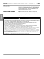
DANGER
HAZARD OF ELECTRIC SHOCK, EXPLOSION, OR ARC FLASH
• Apply appropriate personal protective equipment (PPE) and follow safe electrical work practices.
See NFPA 70E or CSA Z462.
• This equipment must only be installed and serviced by qualified electrical personnel.
• At least two people should always perform the installation work.
• Turn off all power supplying this equipment before working on or inside the equipment.
• Always use a properly-rated voltage sensing device to confirm all power is off.
• Replace all devices, doors and covers before turning on power to this equipment.
• Read and understand this entire instruction bulletin and the latest edition of the NEMA PB 1.1 standards publication included
before installing, operating, or maintaining this equipment.
• Read and understand the entire instruction bulletin 80043-309-XX before installing this retrofit kit.
• Local codes vary, but are adopted and enforced to promote safe electrical installations. A permit may be needed to do
electrical work, and some codes may require an inspection of the electrical work.
Failure to follow these instructions will result in death or serious injury.
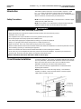
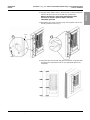
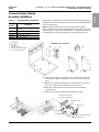
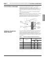
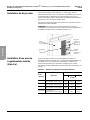
Circuit Breaker Installation To install a PowerPact™ H/J/L frame circuit breaker with Micrologic 5/6 into
an I-Line panelboard, and for the blank extensions that are to be used with
them, refer to the latest version of the I-Line Circuit Breaker Power
Distribution Panelboards, document number 80043-309-xx.
Please review all instructions supplied with the circuit breaker before
beginning this installation.
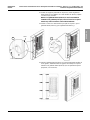
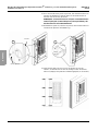
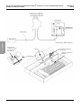
NOTE: To have access to the Micrologic display, a new deadfront
assembly is required. Contact Schneider Electric Customer Support
1-888-Square D (1-888-778-2733).
New deadfront
assembly
Blank
extension
PowerPact H
or J frame with
Micrologic 5/6
Micrologic
LCD display

PowerPact™ H-, J-, or L-Frame Circuit Breaker with Micrologic™ 5/6 Retrofit Instructions 80043-801-01
Side Car Installation 03/2013
© 2013 Schneider Electric All Rights Reserved5
ENGLISH
Side-Car Installation A side-car enclosure addition is required to be added to an existing I-Line
panelboard installation to house additional components that are used with
PowerPact H/J/L frame circuit breakers with Micrologic 5/6. This enclosure
is used to contain the power supply assembly (and communications
modules, if required).
Tools Needed •Flat -head screwdriver
•#2 square screwdriver
•Torx® driver T25
•Drill with 11/64 in. (4.4 mm) drill bit
•Drill with 7/16 in. (11.1 mm) drill bit
•Socket wrench with 9/16 socket
•Socket wrench with 5/16 socket
•5 in. (127 mm) hole saw
Installation 1. Turn off all power supplying the panelboard before working on or
inside equipment. Verify power is off, using a properly rated voltage
sensing device.
2. Identify the side of the panelboard where the side-car will be attached.
The PowerPact H-, J-, or L-frame circuit breaker with Micrologic 5/6
trip unit should be installed on the same side of the I-Line stack as
the side-car.
Table 1: Side-car Enclosure Catalog Numbers
Catalog
Number Application
Side-Car Box Dimensions
Height Width Depth
Inches (mm)
SIDECAR50 HCP panelboards,
50 in. (1,270 mm) box height 50
(1,270) 14
(356) 9.5
(241)
SIDECAR59 HCP panelboards,
59 in. (1,499 mm) box height 59
(1,499) 14
(356) 9.5
(241)
SIDECAR68 HCP panelboards,
68 in. (1,727 mm) box height 68
(1,727) 14
(356) 9.5
(241)
SIDECAR86 HCP/HCRU/HCPSU panelboards,
86 in. (2,184 mm) box height 86
(2,184) 14
(356) 9.5
(241)

80043-801-01 PowerPact™ H-, J-, or L-Frame Circuit Breaker with Micrologic™ 5/6 Retrofit Instructions
03/2013 Side Car Installation
© 2013 Schneider Electric All Rights Reserved 6
ENGLISH
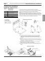
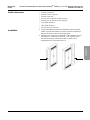
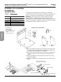
3. Remove the panelboard trim and internal deadfront assembly.
4. Disconnect and move aside all branch wiring located in the gutter
space of the panelboard, where the side-car will be installed.
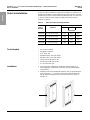
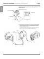
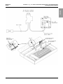
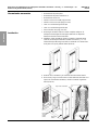
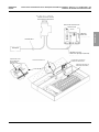
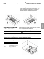
5. If installing a power supply assembly only, mark and drill a 5 inch
(127 mm) diameter hole, into the side of the enclosure, 20 inches
(508 mm) from the top of the unit for the control power wiring (A).
6. If also installing a communications module assembly, drill a second
5 inch (127 mm) diameter hole spaced 20 inches (508 mm) from the
center of the first hole (B), drilled in step 5.
7. Install the gaskets, provided, around the edge of the drilled 5 inch
(127 mm) diameter holes (C).
Gutter space
Internal
deadfront
assembly Panelboard
trim
20 in.
(508 mm)
Ø 5°
(127 mm)
A B C
Top Top Top
20 in.
(508 mm)
Ø 5°
(127 mm)

PowerPact™ H-, J-, or L-Frame Circuit Breaker with Micrologic™ 5/6 Retrofit Instructions 80043-801-01
Side Car Installation 03/2013
© 2013 Schneider Electric All Rights Reserved7
ENGLISH
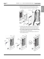
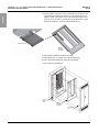
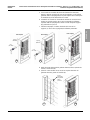
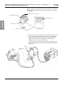
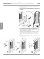
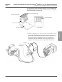
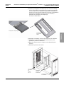
8. Remove the side-car hinged door from side-car enclosure by removing
the screws, retain the screws (D).
9. Remove the four 1/4-20 bolts from the side corners of the existing
panelboard enclosure, retain the screws (E).
10.Position the side-car enclosure next to the panelboard. Align the four
elongated holes, in each corner of the side-car, with the panelboard
holes (F).
11.Drill four 25/84 inch (9.9 mm) diameter clearance holes into the
panelboard enclosure, using the side-car enclosure as a template (G).
Side-car
hinged door
D E
Side-car’s holes to be
used as template
Panel
Side-car
Panelboard enclosure hole
Elongated
side-car hole
Panelboard
enclosure
F G

80043-801-01 PowerPact™ H-, J-, or L-Frame Circuit Breaker with Micrologic™ 5/6 Retrofit Instructions
03/2013 Side Car Installation
© 2013 Schneider Electric All Rights Reserved 8
ENGLISH
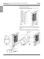
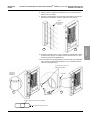
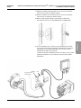
12.Using the holes drilled in step 11, attach the side-car to the panelboard
with four 3/8-16 screws, and secure with nuts, provided (H).
NOTE: If the side-car is not properly attached to the main
enclosure (as shown in previous steps), it must be
individually grounded.
13.Reinstall the four screws, removed in step 9, through the side-car and
into the panelboard enclosure (J).
14.Attach the side-car to the wall, with grade 5 steel bolts, using all the wall
mounting holes located in the side-car (use appropriate wall anchor,
if required).
Panel
Side-car
Panel
Side-car
H J

PowerPact™ H-, J-, or L-Frame Circuit Breaker with Micrologic™ 5/6 Retrofit Instructions 80043-801-01
Power Supply Assembly Installation 03/2013
© 2013 Schneider Electric All Rights Reserved9
ENGLISH
Power Supply Assembly
Installation Replacement circuit breaker must be ordered with 24 V harness as a suffix
in the circuit breaker part number.
NOTE: This retrofit kit is only for retrofitting PowerPact H/J/L frame circuit
breakers with Micrologic.
15.Remove all metal shavings with a vacuum prior to connecting
any wiring.
16.Install and connect power supply assembly (K), (see the section “Power
Supply Assembly Installation”, page 9, for details). If the circuit breaker
is ordered with communications, also install and connect the
communications module assembly (L) (see Communications Module
Assembly Installation, page 12, for details).
K L
NOTICE
HAZARD OF EQUIPMENT DAMAGE
Do not wire any P- or R-frame trip unit to any power supply that is also powering H/J/L frame circuit breakers with Micrologic.
Failure to follow these instructions can result in equipment damage.
Table 2: Power Supply Catalog Numbers
Catalog Number Application
PS208V Power supply for Micrologic H/J/L
frame circuit breakers, 208 Vac panels
PS480V Power supply for Micrologic H/J/L
frame circuit breakers, 480 Vac panels

80043-801-01 PowerPact™ H-, J-, or L-Frame Circuit Breaker with Micrologic™ 5/6 Retrofit Instructions
03/2013 Power Supply Assembly Installation
© 2013 Schneider Electric All Rights Reserved 10
ENGLISH
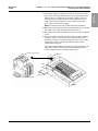
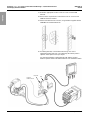
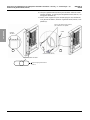
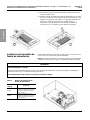
17.Place power supply assembly into the side-car, 12 inches (305 mm)
from the top and centered with the five inch (127 mm) diameter hole,
drilled in step 5. If communications module assembly is also being
installed, this power supply assembly must be located 32 inches
(813 mm) from the top of the side-car and centered on the lower
5 inch hole (127 mm), drilled in step 6.
NOTE: The barrier side should go towards the main panelboard.
18.Mark the four mounting holes into the back wall of the side-car, and drill
four 11/64 inch (4.4 mm) diameter holes into the side-car.
19.Mount the power supply assembly into the side-car using the supplied
screws.
20.Ensure the switch is installed in the proper direction. When installing
the switch, make sure it is mounted so the switch handle must be
pushed UP, toward the TOP of the panelboard, to turn it ON, and the
switch handle must be pushed down, toward the bottom of the
panelboard, to turn it OFF.
If the switch handle is not UP, toward the top of the panelboard, in the
ON position, with the barrier facing the main panelboard, then the
switch should be removed and rotated 180 degrees.
12 in.
(305 mm).
Top
Bottom
Proper direction for installation
Barrier side
Switch handle pushed UP

PowerPact™ H-, J-, or L-Frame Circuit Breaker with Micrologic™ 5/6 Retrofit Instructions 80043-801-01
Power Supply Assembly Installation 03/2013
© 2013 Schneider Electric All Rights Reserved11
ENGLISH
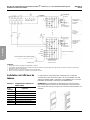
21.If installing Micrologic 5/6 trip units only, without communications, wire
each trip unit to the terminal blocks.
NOTE:
1. Terminal blocks located in the power supply assembly.
2. Use 16 gauge wire minimum, unless otherwise noted.
Terminal blocks

80043-801-01 PowerPact™ H-, J-, or L-Frame Circuit Breaker with Micrologic™ 5/6 Retrofit Instructions
03/2013 Communications Assembly Installation
© 2013 Schneider Electric All Rights Reserved 12
ENGLISH
Communications Module
Assembly Installation
Replacement circuit breaker must be ordered with communications suffix in
part number. Order one COMASSY per panel. Order one STRV00210 (IFM)
for each circuit breaker.
NOTE: All circuit breakers that are to be connected to the Modbus™
Interface Modules (IFMs) should be installed on the same side of the I-Line
stack as the side-car to ensure communications cord length is adequate. Up
to a maximum of five IFMs with repeater can be installed using this kit.
Table 3: Communications Components
Catalog
Number Application
COMASSY Panelboard communications mounting
assembly
TRV00880 ULP line terminator
STRV00210 IFM communications module
STRV00211 Isolated Modbus repeater
TRV00217 Stacking connectors
22.Place communications assembly into side-car above the power supply
assembly and centered on the upper 5 inch (127 mm) hole, drilled in
step 5.
23.Mark the 4 mounting holes into the back wall of the side-car and drill
four 0.173 inch (4.4 mm) diameter holes into the side-car.
24.Mount the communications assembly into the side-car using the
supplied screws.
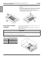
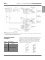
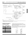
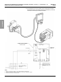
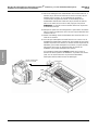
25.Install communication components onto DIN rails as shown.
Communication Components
A. Mounting pan
B. Start clamp
C. End clamp
D. Stacking connector
E. Modbus Interface Module (IFM)
F. Isolated Modbus repeater
A
BC
EF
D
Mounting communication
components onto DIN rails.
A. Mounting pan
B. Start clamp
C. Staking connector
D. End clamp
E. Modbus Interface Module (IFM)
F. Isolated Modbus repeater

PowerPact™ H-, J-, or L-Frame Circuit Breaker with Micrologic™ 5/6 Retrofit Instructions 80043-801-01
Communications Assembly Installation 03/2013
© 2013 Schneider Electric All Rights Reserved13
ENGLISH
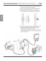
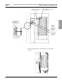
The following arrangements should be followed when installing more than
1 IFM per panel. Up to a maximum of 5 IFMs, with repeater, can be
installed using this kit.
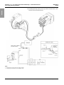
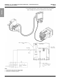
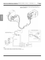
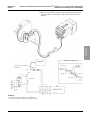
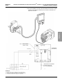
26.Install wiring for communication components per the wiring diagrams
(shown in the next few pages). Connect the first IFM to the power
supply terminal blocks as shown. The remaining IFMs are powered
through the stacking accessory.
See instruction bulletins supplied with the IFM and with the isolated
Modbus repeater module for additional installation details.
Top view
A. Mounting pan
B. Start clamp
D. End clamp
E. Modbus Interface Module (IFM)
F. Isolated Modbus repeater
From the
Modbus master
Repeater IFM
Terminal blocks

80043-801-01 PowerPact™ H-, J-, or L-Frame Circuit Breaker with Micrologic™ 5/6 Retrofit Instructions
03/2013 Front Display Module Installation
© 2013 Schneider Electric All Rights Reserved 14
ENGLISH
Front Display Module
Installation Replacement circuit breaker must be ordered with communications suffix in
part number. If installing only one Front Display Module (FDM), order
FDMSINGLE kit. For every two FDMs installed, order FDMDOUBLE kit.
NOTE: Circuit breakers that are to be connected to FDMs should be
installed on the same side of the I-Line stack as the side-car to ensure
communications cord length is adequate.
NOTE:
1. Terminal blocks located in the control power assembly.
2. If Front Display Module (FDM) is not to being installed, then the ULP line terminator must be connected on this terminal (order ULP line terminator separately).
3. Ground 0V terminal at only one point in the Modbus network.
4. All conductors to be 16 AWG (1.5 mm2) gauge, unless otherwise noted.
Table 4: FDM Components
Catalog
Number Application
STRV00121 Front Display Module (FDM)
TRV00880 ULP line terminator
TRV00820 ULP cord 79 in. (2 meters) length
TRV00830 ULP cord 118 in. (3 meters) length
TRV00850 ULP cord 197 in. (5 meters) length
FDMSINGLE Single FDM mounting bracket
FDMDOUBLE Dual FDM mounting bracket

PowerPact™ H-, J-, or L-Frame Circuit Breaker with Micrologic™ 5/6 Retrofit Instructions 80043-801-01
Front Display Module Installation 03/2013
© 2013 Schneider Electric All Rights Reserved15
ENGLISH
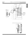
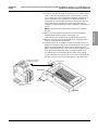
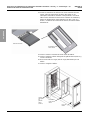
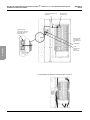
27.Determine appropriate location in side-car cover to mount FDM
brackets.
28.Knock out the required holes located in the side-car cover for each
FDM bracket to be installed.
29.Mount each FDM bracket as shown, using hardware supplied with the
FDMSINGLE or FDMDOUBLE kits.
30.If installing with IFM, connect FDM to IFM using ULP cord of
appropriate length (order ULP cord separately). No further power is
required. Attach power to IFM per step 26.
See instruction bulletins supplied with the IFM, with the isolated
Modbus repeater module and with the FDM for more installation details.
From the
Modbus master
Repeater IFM
Terminal blocks

80043-801-01 PowerPact™ H-, J-, or L-Frame Circuit Breaker with Micrologic™ 5/6 Retrofit Instructions
03/2013 Front Display Module Installation
© 2013 Schneider Electric All Rights Reserved 16
ENGLISH
FDM bracket
(hidden by the side-car
cover in this view)
ULP cord Communication mounting
pan and components
NSX cord (supplied with
the circuit breaker)

PowerPact™ H-, J-, or L-Frame Circuit Breaker with Micrologic™ 5/6 Retrofit Instructions 80043-801-01
Front Display Module Installation 03/2013
© 2013 Schneider Electric All Rights Reserved17
ENGLISH
31.If Installing without IFM, attach power to FDM directly from terminal
block assembly and connect circuit breaker NSX cord to FDM.
NOTE:
1. Terminal blocks located in the power supply assembly.
2. Use 16 gauge wire minimum, unless otherwise noted.
3. Order the ULP Line terminator separately.
Terminal blocks
La page est en cours de chargement...
La page est en cours de chargement...
La page est en cours de chargement...
La page est en cours de chargement...
La page est en cours de chargement...
La page est en cours de chargement...
La page est en cours de chargement...
La page est en cours de chargement...
La page est en cours de chargement...
La page est en cours de chargement...
La page est en cours de chargement...
La page est en cours de chargement...
La page est en cours de chargement...
La page est en cours de chargement...
La page est en cours de chargement...
La page est en cours de chargement...
La page est en cours de chargement...
La page est en cours de chargement...
La page est en cours de chargement...
La page est en cours de chargement...
La page est en cours de chargement...
La page est en cours de chargement...
La page est en cours de chargement...
La page est en cours de chargement...
La page est en cours de chargement...
La page est en cours de chargement...
La page est en cours de chargement...
La page est en cours de chargement...
La page est en cours de chargement...
La page est en cours de chargement...
La page est en cours de chargement...
La page est en cours de chargement...
La page est en cours de chargement...
La page est en cours de chargement...
La page est en cours de chargement...
La page est en cours de chargement...
La page est en cours de chargement...
La page est en cours de chargement...
La page est en cours de chargement...
La page est en cours de chargement...
La page est en cours de chargement...
La page est en cours de chargement...
La page est en cours de chargement...
La page est en cours de chargement...
La page est en cours de chargement...
La page est en cours de chargement...
La page est en cours de chargement...
La page est en cours de chargement...
La page est en cours de chargement...
-
 1
1
-
 2
2
-
 3
3
-
 4
4
-
 5
5
-
 6
6
-
 7
7
-
 8
8
-
 9
9
-
 10
10
-
 11
11
-
 12
12
-
 13
13
-
 14
14
-
 15
15
-
 16
16
-
 17
17
-
 18
18
-
 19
19
-
 20
20
-
 21
21
-
 22
22
-
 23
23
-
 24
24
-
 25
25
-
 26
26
-
 27
27
-
 28
28
-
 29
29
-
 30
30
-
 31
31
-
 32
32
-
 33
33
-
 34
34
-
 35
35
-
 36
36
-
 37
37
-
 38
38
-
 39
39
-
 40
40
-
 41
41
-
 42
42
-
 43
43
-
 44
44
-
 45
45
-
 46
46
-
 47
47
-
 48
48
-
 49
49
-
 50
50
-
 51
51
-
 52
52
-
 53
53
-
 54
54
-
 55
55
-
 56
56
-
 57
57
-
 58
58
-
 59
59
-
 60
60
-
 61
61
-
 62
62
-
 63
63
-
 64
64
-
 65
65
-
 66
66
-
 67
67
-
 68
68
-
 69
69


Schneider Electric PowerPact H L-Frame Circuit Breaker Mode d'emploi
- Taper
- Mode d'emploi
dans d''autres langues
Documents connexes
-
Schneider Electric JYT66352 Mode d'emploi
-
Schneider Electric PowerPact Manuel utilisateur
-
Schneider Electric JYT65471 Manuel utilisateur
-
Schneider Electric PowerPacT™ H- and J-Frame Circuit Breakers and Switches Mode d'emploi
-
-
-
-
-
-
