Maytag MLE20PDBZW2 Guide d'installation
- Catégorie
- Machines à laver
- Taper
- Guide d'installation
Ce manuel convient également à

I STALLATI
I CTI
COMMERCIAL STACKED WASHER/DRYER
GAS OR ELECTRIC
I CTI
/
LAVEUSE/SECHEUSE SUPERPOSEES
A USAGE COMMERCIAL
A GAZ OU ELECTRIGUE
TABLE OF CONTENTS
Page
Stacked Washer/Dryer Safety ................................................................ 2
Tools & Parts .............................................................................................. 5
Alternate Parts and Accessories ............................................................ 6
Dimensions/Clearances .......................................................................... 7
Stacked Washer/Gas Dryer Installation Requirements ................... 8
Stacked Washer/Electric Dryer
Installation Requirements ..................................................................... 10
Dryer Venting Requirements ............................................................... 12
Dryer Gas Supply Requirements ....................................................... 15
Installing Stacked Washer/Dryer ........................................................ 16
Washer Drain System ........................................................................... 19
Leveling ...................................................................................................... 20
Complete Installation .............................................................................. 21
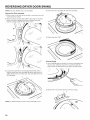
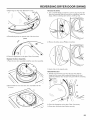
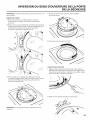
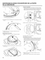
Reversing Dryer Door Swing ................................................................ 22
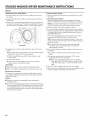
Stacked Washer/Dryer Maintenance Instructions ........................... 24
If You Need Assistance .......................................................................... 25
Electronic Control Setup Instructions ............................................... 26
Warranty ................................................................................................... 32
TABLE DES MATII_RES
Page
Securite de la laveuse/secheuse superposees ............................... 33
Outils et pieces ...................................................................................... 36
Pieces supplGmentaires et accessoires ............................................ 37
Dimensions/Distances de degagement ........................................... 38
Exigences d'installation pour la laveuse/sGcheuse & gaz
superposees ............................................................................................. 39
Exigences d'installation pour la laveuse/sGcheuse 61ectriques
superposees .......................................................................................... 41
Exigences concernant 1'Gvacuation de la secheuse ...................... 43
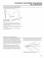
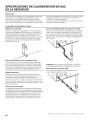
Specifications de I'alimentation en gaz de la secheuse ............... 46
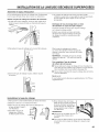
Installation de la laveuse/secheuse superposees ........................... 47
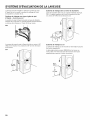
Systeme d'Gvacuation de la laveuse ................................................... 50
Nivellement ................................................................................................ 51
Achever I'installation ................................................................................ 52
Inversion du sens d'ouverture de la porte de la secheuse ............. 53
Instructions d'entretien de la laveuse/secheuse superposees ....55
Si vous avez besoin d'assistance ........................................................ 56
Instructions de reglage du tableau
de commande 61ectronique .................................................................. 57
Garanfie ................................................................................................... 64
W10434041 B www.maytagcom mercialla und ry.com

STACKED WASHER/DRYER SAFETY
Your safety and the safety of others are very important.
We have provided many important safety messages in this manual and on your appliance. Always read and obey all safety
messages.
This is the safety alert symbol.
This symbol alerts you to potential hazards that can kill or hurt you and others.
All safety messages will follow the safety alert symbol and either the word "DANGER" or "WARNING."
These words mean:
You can be killed or seriously injured if you don't immediately
follow instructions.
You can be killed or seriously injured if you don't follow
instructions.
All safety messages will tell you what the potential hazard is, tell you how to reduce the chance of injury, and tell you what can
happen if the instructions are not followed.
WARNING - of
=Clothes dryer installation must be performed by a qualified installer,
= install the clothes dryer according to the manufacturer's instructions and local codes.
- Do not install a clothes dryer with flexible plastic venting materials or flexible metal
(foil type) duct. if flexible metal duct is installed, it must be of a specific type identified
by the appliance manufacturer as suitable for use with clothes dryers. Flexible venting
materials are known to collapse, be easily crushed, and trap lint. These conditions will
obstruct clothes dryer airflow and increase the risk of fire.
- To reduce the risk of severe injury or death, follow all installation instructions,
=Save these instructions.
It is recommended that the owner post, in a prominent location, instructions for the customer's use in the event the customer
smells gas. This information should be obtained from your gas supplier.
m Post the following warning in a prominent location.
i FOR YOUR SAFETY
Do not store or use gasoline or other flammable vapors and liquids in the vicinity of this or any other appliance.
i

STACKED WASHER/DRYER SAFETY
WARNING: For your safety, the information in this manual must be followed to minimize I
the risk of fire or explosion, or to prevent property damage, personal injury, or death, j
- Do not store or use gasoline or other flammable vapors and liquids in the vicinity of this
or any other appliance.
- WHAT TO DO iF YOU SMELL GAS:
= Do not try to light any appliance.
• Do not touch any electrical switch; do not use any phone in your building.
• Clear the room, building, or area of all occupants.
o Immediately call your gas supplier from a neighbor's phone. Follow the gas supplier's
instructions.
• if you cannot reach your gas supplier, call the fire department.
- Installation and service must be performed by a qualified installer, service agency, or
the gas supplier.
WARNING: Gas leaks cannot always be detected by smell.
Gas suppliers recommend that you use a gas detector approved by UL or CSA.
For more information, contact your gas supplier.
If a gas leak is detected, follow the "What to do if you smell gas" instructions.
iMPORTANT: The gas installation must conform with local codes, or in the absence of local codes, with the Canadian Natural Gas
and Propane Installation Code, CSA B149.1.
The dryer must be electrically grounded in accordance with local codes, or inthe absence of local codes, with the Canadian
Electrical Code, CSA C22.1.
3

STACKED WASHER/DRYER SAFETY
iMPORTANT SAFETY iNSTRUCTiONS
WARNING: To reduce the risk of fire, electric shock, or injury to persons when using the washer/dryer, follow basic
precautions, including the following:
[] Read all instructions before using the washer/dryer.
[] Do not place items exposed to cooking oils in your dryer.
items contaminated with cooking oils may contribute to a
chemical reaction that could cause a load to catch fire.
[] Do not wash or dry articles that have been previously
cleaned in, washed in, soaked in, or spotted with gasoline,
dry-cleaning solvents, other flammable, or explosive
substances as they give off vapors that could ignite or
explode.
[] Do not add gasoline, dry=cleaning solvents, or other
flammable, or explosive substances to the wash water.
These substances give off vapors that could ignite or
explode.
[] Do not allow children to play on or in the washer/dryer.
Close supervision of children is necessary when the
washer/dryer is used near children.
[] Before the washer/dryer is removed from service or
discarded, remove the doors to the washer/dryer
compartments.
[] Do not reach into the washer/dryer if the tub, agitator or
drum is moving.
[] Do not install or store the washer/dryer where it will be
exposed to the weather.
[] Do not tamper with controls.
[] Clean dryer lint screen before or after each load.
[] Under certain conditions, hydrogen gas may be produced
in a hot water system that has not been used for 2 weeks
or more. HYDROGEN GAS iS EXPLOSIVE. if the hot water
system has not been used for such a period, before using
the washing machine, turn on all hot water faucets and let
the water flow from each for several minutes. This will
release any accumulated hydrogen gas. As the gas is
flammable, do not smoke or use an open flame during
this time.
[] Do not repair or replace any part of the washer/dryer or
attempt any servicing unless specifically recommended in
this Use and Care Guide or in published user=repair
instructions that you understand and have the skills to
carry out.
[] Do not use fabric softeners or products to eliminate static
unless recommended by the manufacturer of the fabric
softener or product.
[] Do not use heat to dry articles containing foam rubber or
similarly textured rubber-like materials.
[] Keep area around the exhaust opening and adjacent
surrounding areas free from the accumulation of lint, dust,
and dirt.
[] The interior of the machine and dryer exhaust vent should
be cleaned periodically by qualified service personnel
[] See "Electrical Requirements" section of the Installation
Instructions booklet for grounding instructions.
SAVE THESE iNSTRUCTiONS
4

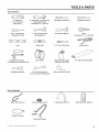
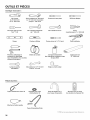
Tools Needed:
8" (203 ram)
or I0" (254 ram)
Pipe Wrench
Torx _ T-20 Security
Screwdriver or Bit
Level
TOOLS & PARTS
8" (203 mm) or 10" (254 ram)
Adj ustable Wrench
That Opens to 1" (25 ram)
1" (25 ram) Hex-Head
Socket Wrench
Utility Knife
Flat-Blade Screwdriver
5/16" Socket Wrench
1/4" (6 ram) Nut Driver
Phillips Screwdriver
Pliers
(that open to 19/10"[39 mini)
Locking Pliers
Caulk Gun and Caulk Vent Clamps Pipe-Joint Compound
(for installing new exhaust vent) Suitable for Gas Type
27" (686 ram) Wood Block
Flashlight (optional)
112" (13 ram) and 9/16"
(14 ram) Open-End Wrenches
Ruler or Measuring Tape
Parts Supplied:
Water Inlet Hoses (2)
Beaded Tie Strap
Inlet Hose Washers (4)
Drain Hose/Clamp
U-Shaped Hose Form Transit Bolt Hole Plug (4)
t-_:' TORX is a registered trademark of Saturn Fasteners, Inc. 5

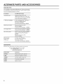
ALTERNATE PARTS AND ACCESSORIES
Alternate Parts
Your installation may require additional parts. If you are interested
in purchasing one of the items listed here, call the toIFfree number
in the "If You Need Assistance" section.
If You Have You Will Need to Buy
Overhead sewer Standard 20 gal. (76 L) 39"
(990 mm) tall drain tub or utility sink,
sump pump and connectors (available
from local plumbing suppliers)
1" (25 mm) standpipe 2" (51 mm) diameter to 1" (25 mm)
diameter Standpipe Adapter
Part Number 3363920
Connector Kit Part Number 285835
Drain hose too short Extension Drain Hose Part
Number 285863
Connector Kit Part Number 285835
Lint clogged drain Drain Protector Part Number 367031
Connector Kit Part Number 285835
Floor drain system Siphon break, Part Number 285834
Connector Kit (x2) Part Number
285835
Extension Drain Hose Part
Number 285863
Water faucets
beyond reach
of fill hoses
2 longer water fill hoses:
6 ft. (1.8 m) 90 ° bend hose
Part Number 76314
10 ft. (3.0 m) Part Number 350008
Accessories
Enhance your washer/dryer with these premium accessories.
For more high-quality items or to order,
call 1-800-807-6777 or visit us at
www.whirlpoolparts.ca.
Part Number Accessory
8212526 Washer drip tray, fits under all
31682 AIFpurpose appliance cleaner
1903WH Laundry supply storage cart
279818 3-way dryer venting kit
285834 Siphon break kit

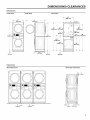
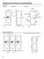
DiM ENS iONS/CLEARANCES
Dimensions
Front View Side View Back View
74"
(188(ram)
_ 27" _
(686 ram)
5J "
(1295 ram)
74"
1880 ram)
i_,, 291/2" _ _,,
(25 ram) (751 ram) (25 ram)
T
27 _l
_ 61/2''
(165 ram)
1ii
(25 mm)
661/4 ''
(1683 ram)
61/. ''
{159 ram)
41/8'' 69"
(105 ram) (1753 ram)
36"
(914 mm)
1
Clearances
Side Clearances
Back/Top Clearances
O" _ '._ O"
(O ram) (O ram)
j__ j_
©
,.,,i-..--O" 4 "-'''i_
(Omm) ('102mm)
7

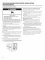
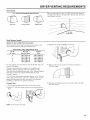
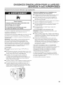
STACKED WASHER/GAS DRYER iNSTALLATiON
REQUIREMENTS
Stacked Washer/Gas Dryer Location
Explosion Hazard
Keep flammable materials and vapors, such as
gasoline, away from dryer.
Do not install in a garage.
Failure to do so can result in death, explosion, or fire.
Selecting the proper location for your washer/dryer improves
performance and minimizes noise and possible washer "walk"
Your washer/dryer can be installed in a basement, laundry room, or
recessed area. See "Drain System:'
Companion appliance location requirements should also be
considered.
IMPORTANT: Do not install or store the washer/dryer where it will
be exposed to the weather. Do not store or operate the washer/
dryer in temperatures at or below 32°F (0°C). Some water can
remain in the washer and can cause damage in low temperatures.
Proper installation is your responsibility.
You will need:
m A water heater set to deliver 120°F (49°C) water to the washer.
m Hot and cold water faucets located within 4 ft. (1.2 m) of the
hot and cold water fill valves, and water pressure of 20-100
psi (137.9-689.6 kPa).
m A level floor with a maximum slope of 1" (25 mm) under
entire washer/dryer. Installing the washer/dryer on soft floor
surfaces, such as carpets or surfaces with foam backing, is not
recommended.
A sturdy and solid floor to support the washer/dryer with
a total weight (water and load) of 450 Ibs (204 kg).
m A floor drain under the bulkhead. Prefabricated bulkheads with
electrical outlets, water inlet lines, and drain facilities should be
used only where local codes permit.
Stacked washer/gas dryer installation clearances
m The location must be large enough to allow the washer
and dryer doors to be fully opened.
m Additional spacing should be considered for ease of installation
and servicing. The doors open more than 180 °. The washer
door is not reversible.
m Additional clearances might be required for wall, door, and floor
moldings.
m Additional spacing of 1" (25 mm) on all sides of the washer/
dryer is recommended to reduce noise transfer.
m Companion appliance spacing should also be considered.
When installing a gas dryer:
IMPORTANT: Observe all governing codes and ordinances.
m Check code requirements: Some codes limit or do not
permit installation of clothes dryers in garages, closets,
or sleeping quarters. Contact your local building inspector.
m Make sure that lower edges of the cabinet, plus the back and
bottom sides of the washer, are free of obstructions to permit
adequate clearance of air openings for combustion air. See
"Recessed Area Installation Instructions" below for minimum
spacing requirements.
Recessed Area Installation Instructions
This washer/dryer may be installed in a recessed area. For
recessed area installations, minimum clearances can be found
on the warning label on the rear of the dryer or in "Dimensions/
Clearances_'
The installation spacing is in inches and is the minimum allowable.
Additional spacing should be considered for ease of installation,
servicing, and compliance with local codes and ordinances.
The dryer must be exhausted outdoors.
iii
8

STACKED WASHER/GAS DRYER iNSTALLATiON
REQUIREMENTS
Stacked Washer/Gas Dryer Electrical Requirements Stacked Washer/Gas Dryer Gas Supply
IM PORTANT: The washer/dryer must be electrically grounded
in accordance with local codes and ordinances or, in the
absence of local codes, with the Canadian Electrical Code, CSA
C22.1. If codes permit and a separate ground wire is used, it is
recommended that a qualified electrical installer determine that the
ground path is adequate.
A copy of the above code standards can be obtained from:
CSA International
8501 East Pleasant Valley Road
Cleveland, Ohio 44131-5575
lu Do not ground to a gas pipe.
lu Do not have a fuse in the neutral or ground circuit.
In A 120 volt, 60 Hz, AC only, 15- or 20-amp, fused electrical
circuit is required. A time-delay fuse or circuit breaker is also
recommended. It is recommended that a separate circuit
serving only this washer/dryer be provided.
In If codes permit and a separate ground wire is used, it is
recommended that a qualified electrician determine that the
ground path is adequate.
In Check with a qualified electrician if you are not sure the
washer/dryer is properly grounded.
Explosion Hazard
Use a new CSA International approved gas supply line.
Install a shut=off valve.
Securely tighten all gas connections.
If connected to LP, have a qualified person make sure
gas pressure does not exceed 13" (330 ram) water
column.
Examples of a qualified person include:
licensed heating personnel,
authorized gas company personnel, and
authorized service personnel.
Failure to do so can result in death, explosion, or fire.
Stacked Washer/Gas Dryer Grounding
GROUNDING INSTRUCTIONS
For a permanently connected washer/dryer:
This appliance must be connected to a grounded metal,
permanent wiring system, or an equipment grounding
conductor must be run with the circuit conductors and
connected to the equipment=grounding terminal or lead
on the appliance.
WARNING" Improper connection of the equipment-
grounding conductor can result in a risk of electric shock.
Check with a qualified electrician or service representative
or personnel if you are in doubt as to whether the appliance
is properly grounded.
SAVE THESE INSTRUCTIONS
I MPORTANT: Observe all governing codes and ordinances.
This installation must conform with all local codes and ordinances.
In the absence of local codes, installation must conform with CAN/
CSA B149.
A copy of the above code standards can be obtained from:
CSA International
8501 East Pleasant Valley Road
Cleveland, Ohio 44131-5575
The design of this washer/dryer has been certified by CSA
International for use at altitudes up to 10,000 feet (3048 m) above
sea level at the B.T.U. rating indicated on the model/serial plate.
Burner input adjustments are not required when the washer/dryer
is operated up to this elevation.
When installed above 10,000 feet (3048 m), a four percent (40/0)
reduction of the burner B.T.U. rating shown on the model/serial
plate is required for each 1,000 foot (305 m) increase in elevation.
For assistance when converting to other gas types and/or installing
above 10,000 feet (3048 m) elevation, contact your local service
company.
9

STACKED WASHER/ELECTRIC DRYER iNSTALLATiON
REQUIREMENTS
Stacked Washer/Electric Dryer Location
Explosion Hazard
Keep flammable materials and vapors, such as
gasoline, away from dryer.
Do not instafl in a garage.
Failure to do so can result in death, explosion, or fire.
Selecting the proper location for your washer/dryer improves
performance and minimizes noise and possible washer "walk/'
Your washer/dryer can be installed in a basement, laundry room, or
recessed area. See "Drain System/'
Companion appliance location requirements should also be
considered.
IM PORTANT: Do not install or store the washer/dryer where it will
be exposed to the weather. Do not store or operate the washer/dryer
in temperatures at or below 32°F (0°C). Some water can remain
in the washer and can cause damage in low temperatures. Proper
installation is your responsibility.
You will need:
m A water heater set to deliver 120°F (49°0) water to the washer.
m Hot and cold water faucets located within 4 ft. (1.2 m) of the
hot and cold water fill valves, and water pressure of 20-100 psi
(137.9-689.6 kPa).
m A level floor with a maximum slope of 1" (25 mm) under
entire washer/dryer. Installing the washer/dryer on soft floor
surfaces, such as carpets or surfaces with foam backing, is not
recommended.
m A sturdy and solid floor to support the washer/dryer with a total
weight (water and load) of 450 Ibs (204 kg).
m A floor drain under the bulkhead. Prefabricated bulkheads with
electrical outlets, water inlet lines, and drain facilities should be
used only where local codes permit.
Stacked washer/electric dryer installation clearances
m The location must be large enough to allow the washer and
dryer doors to be fully opened.
In Additional spacing should be considered for ease of installation
and servicing. The doors open more than 180 °. The washer
door is not reversible.
In Additional clearances might be required for wall, door, and floor
moldings.
In Additional spacing of 1" (25 mm) on all sides of the washer/
dryer is recommended to reduce noise transfer.
m Companion appliance spacing should also be considered.
Recessed Area Installation Instructions
This washer/dryer may be installed in a recessed area. For
recessed area installations, minimum clearances can be found on
the warning label on the rear of the dryer.
The installation spacing is in inches and is the minimum allowable.
Additional spacing should be considered for ease of installation,
servicing, and compliance with local codes and ordinances.
The dryer must be exhausted outdoors.
10

STACKED WASHER/ELECTRIC DRYER iNSTALLATiON
REQUIREMENTS
Stacked Washer/Electric Dryer Electrical
Requirements
Washer Electrical Requirements
Do not have a fuse in the neutral or ground circuit.
m If codes permit and a separate ground wire is used, it is
recommended that a qualified electrician determine that
the ground path is adequate.
m Check with a qualified electrician if you are not sure the washer
is properly grounded.
Stacked Washer/Electric Dryer Grounding
GROUNDING iNSTRUCTiONS
For a permanently connected washer/dryer:
This appliance must be connected to a grounded metal,
permanent wiring system, or an equipment grounding
conductor must be run with the circuit conductors and
connected to the equipment-grounding terminal or lead
on the appliance.
WARNING: Improper connection of the equipment-
grounding conductor can result in a risk of electric shock.
Check with a qualified electrician or service representative
or personnel if you are in doubt as to whether the appliance
is properly grounded.
SAVE THESE iNSTRUCTiONS
Dryer Electrical Requirements
It isyour responsibility:
m To contact a qualified electrical installer.
m To be sure that the electrical connection is adequate and in
conformance with the Canadian Electrical Code.
The Canadian Electrical Code requires a 4-wire power supply
connection.
m To supply the required 4 wire, single phase, 240 volt, 60 Hz.,
AC only electrical supply (or 4 wire, 120/208 volt electrical
supply, if specified on the serial/rating plate) on a separate
40-amp circuit, fused on both sides of the line. A time delay
fuse or circuit breaker is recommended. Connect to an
individual branch circuit. Do not have a fuse in the neutral
or grounding circuit.
m Do not use an extension cord.
m If codes permit and a separate ground wire is used, it is
recommended that a qualified electrician determine that the
ground path is adequate.
Electrical Connection
This dryer is supplied/fitted with an electrical
supply cord and plug. It should be connected
to a 4-wire electrical supply receptacle of
NEMA Type 14-50P, at the voltage shown
on the rating plate. The dryer must be
positioned so that the plug is clearly visible and
accessible. This plug also provides the function
of an emergency stop control for the user. If the
fitted plug is not used, the electrical connection
4-Wire Receptacle
(14-50P)
must be carried out by a competent electrician in accordance with
local or national codes.
If the supply cord is damaged, it must be replaced with a specially
terminated cord by an authorized service agent or a similarly
competent person in order to avoid a hazard.
11

DRYER VENTING REQUIREMENTS
Fire Hazard
Use a heavy metal vent.
Do not use a plastic vent.
Do not use a metal foil vent,
Failure to follow these instructions can result in death
or fire.
WARN ING: To reduce the risk of fire, this dryer MUST BE
EXHAUSTED OUTDOORS.
IMPORTANT: Observe all governing codes and ordinances.
Dryer exhaust must not be connected into any gas vent, chimney,
wall, ceiling, attic, crawlspace, or a concealed space of a building.
Only rigid or flexible metal vent shall be used for exhausting.
4" (102 ram) heavy, metal exhaust vent
[] Only a 4" (102 mm) heavy, metal exhaust vent and clamps may
be used.
[] Do not use plastic or metal foil vent.
Rigid metal vent:
[] Recommended for best drying performance and to avoid
crushing and kinking.
Flexible metal vent: (Acceptable only if accessible to
clean)
[] Must be fully extended and supported in final dryer location.
[] Remove excess to avoid sagging and kinking that may result in
reduced airflow and poor performance.
[] Do not install in enclosed walls, ceilings, or floors.
[] The total length should not exceed 73/4ft. (2.4 m).
NOTE: If using an existing vent system, clean lint from entire length
of the system and make sure exhaust hood is not plugged with
lint. Replace plastic or metal foil vents with rigid metal or flexible
metal vents. Review "Vent System Chart" and if necessary, modify
existing vent system to achieve best drying performance.
Elbows:
[] 45 ° elbows provide better airflow than 90 ° elbows.
Be
Clamps:
[] Use clamps to seal all joints.
[] Exhaust vent must not be connected or secured with screws
or other fastening devices that extend into interior of duct and
catch lint. Do not use duct tape.
Improper venting can cause moisture and lint to collect
indoors, which may result in:
[] Moisture damage to woodwork, furniture, paint, wallpaper,
carpets, etc.
[] Housecleaning problems and health problems.
12

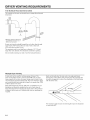
DRYER VENTING REQUIREMENTS
Vent Hoods
4" (102 mm) Diameter Exhaust Hoods
Box Hood Louvered Hood Angled Hood
Exhaust hood must be at least 12" (305 mm) from the ground or
any object that may be in the path of the exhaust (such as flowers,
rocks, bushes, or snow).
Vent System Length
Maximum Vent Length/Vent Connection
Maximum length of vent system depends upon the type of vent
used, number of elbows, and type of exhaust hood.
3. Tighten hose clamp with Phillips screwdriver.
Vent System Chart (Rigid Metal Vent)
No. of Box and Angled
90° Turns Louvered Hood Hood
0
1
2
3
4
135 ft. (41.2 m)
125 ft. (38.1 m)
115 ft. (35.1 m)
106 ft. (32.3 m)
98 ft. (29.9 m)
129 ft. (39.3 m)
119 ft. (36.3 m)
109 ft. (33.2 m)
100 ft. (30.5 m)
92 ft. (28.0 m)
\
For vent systems not covered by the vent specification chart, see
your parts distributor.
Provision must be made for enough air for combustion and
ventilation. (Check governing codes and ordinances.) See
"Recessed Area Installation Instructions" in the "Stacked Washer/
Gas Dryer Location" and "Stacked Washer/Electric Dryer
Location" sections.
A 4" (102 mm) outlet hood is preferred. However, a 21/2'' (64 mm)
outlet exhaust hood may be used. A 21/2'' (64 mm) outlet creates
greater back pressure than other hood types. For permanent
installation, a stationary vent system is required.
Connect Vent
1. If connecting to existing vent, make sure the vent is clean.
2. Using a 4" (102 ram) clamp, connect vent to exhaust outlet in
dryer.
jyvoo,oo,,o,
4. Make sure the vent is secured to exhaust hood with a 4"
(102 ram) clamp.
5. Move dryer into final position. Do not crush or kink vent. Make
sure dryer is level.
NOTE: Do not remove vent collar.
13

DRYER VENTING REQUIREMENTS
If an Exhaust Hood Cannot be Used
The outside end of main vent should have a sweep elbow directed
downward.
*M,n,mumclearanceabove_--
a_c_mulation of snow ice ory
debris such as leaves
If main vent travels vertically through the roof, rather than through
wall, install a 180 ° sweep elbow on end of vent at least 2 fl.
(610 mm) above surface of roof.
The opening in wall or roof shall have a diameter 1/2" (13 mm)
larger than vent diameter. Vent should be centered in opening.
Do not install screening over end of vent for best performance.
Multiple Dryer Venting
A main vent can be used for venting a group of dryers. The
main vent should be sized to remove 200 CFM of air per dryer.
Large-capacity lint screens of proper design may be used in main
vent if checked and cleaned frequently. The room where the dryers
are located should have make-up air equal to or greater than CFM
of all the dryers in the room.
Back-draft Damper Kit, Part No. 339191 O, is available from your
distributor and should be installed in the vent of each dryer to
keep exhausted air from returning into dryers and to keep exhaust
in balance within main vent. Unobstructed return air openings are
required.
Each vent should enter the main vent at an angle pointing in
the direction of the airflow. Vents entering from the opposite side
should be staggered to reduce the exhausted air from interfering
with the other vents.
The maximum angle of each vent entering the main vent should be
no more than 30 °,
14

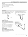
DRYER GAS SUPPLY REQUIREMENTS
Type of Gas
This dryer is equipped for use with natural gas. It is design-certified
by CSA International for LP (propane and butane) gases with
appropriate conversion. No attempt shall be made to convert dryer
from gas specified on serial/rating plate for use with a different gas
without consulting the serving gas supplier. Conversion must be
done by a qualified service technician.
Gas conversion kit part numbers are listed on gas valve burner
base.
Gas Supply Line
Recommended Method
Provide a gas supply line of 1/2" (1 3 mm) rigid (IPS) pipe to dryer
location. Pipe joint compounds that resist action of LP gas must be
used. Do not use TEFLON Rttape. With LP gas, piping or tubing
size can be 1/2" (1 3 mm) minimum. Usually, LP gas suppliers
determine size and materials used in the system.
Flexible Metal Appliance Connector
It is recommended that a new flexible stainless steel gas line,
design-certified by CSA International, be used for connecting the
dryer to the gas supply line. (The gas pipe which extends through
the lower rear of the dryer is provided with 3/8" (10 mm) male pipe
thread.)
Gas Supply Pressure Testing
A 1/8" (3 mm) NPT minimum plugged tapping, accessible for
gauge testing, must be installed immediately downstream of the
installed shut-off valve to the dryer (as shown above). The dryer
must be disconnected from the gas supply piping system during
any pressure testing of the system at test pressures in excess of
1/2" psig (352 kg/m2).
AIternate Method
The gas supply may also be connected using 3/8" (10 mm)
approved copper or aluminum tubing. If the total length of the
supply line is more than 20 ft. (6.1 m), larger tubing will be
required.
If using natural gas, do not use copper tubing. Pipe joint
compounds that resist action of type of gas supplied must
be used.
Shut-off valve required
The supply line must be equipped with an individual manual
shut-off valve installed within 6 ft. (1.8 m) of dryer in accordance
with the B149 installation codes CAN/CGA B149.1 and CAN/
CGA B149.2. This valve should be located in same room as dryer.
It should be in a location that allows ease of opening and closing.
Do not block access to shut-off valve.
NOTE: Do not kink or damage the flexible stainless steel gas line
when moving the door.
Rigid Pipe Connection
The rigid pipe connection requires a combination of pipe fittings to
obtain an in-line connection to dryer.
t-_TEFLON isa registeredtrademarkof E.I.DuPont DeNemoursandCompany.
15

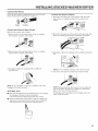
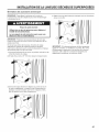
iNSTALLiNG STACKED WASHER/DRYER
Remove Transport System
NOTE: Slide washer/dryer onto cardboard or hardboard before
moving to avoid damaging floor covering.
Excessive Weight Hazard
Use two or more people to move and install washer/dryer,
Failure to do so can result in back or other injury.
IM PORTANT: Position the washer/dryer so that the rear of the
washer is within approximately 3 ft. (900 mm) of its final location.
There are 4 shipping bolts in the rear panel of the washer that
support the suspension system during transportation. These bolts
also retain the power cord inside the washer until the bolts are
removed.
1. Keep the washer/dryer in the upright position while removing
the shipping bolts.
2. Using a 1/2" (13 mm) wrench, loosen each of the bolts.
4. Close the bolt holes with the 4 transport bolt hole plugs.
IMPORTANT: If the washer/dryer is to be transported, call your
product distributor or installer. To avoid suspension and structural
damage, your washer/dryer must be properly set up for relocation
by a trained professional.
J
3. Once the bolt is loose, move it to the center of the hole
and completely pull out the bolt, including the plastic spacer
covering the bolt. Once all 4 bolts are removed, discard the
bolts and spacers.
16

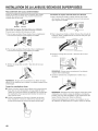
iNSTALLiNG STACKED WASHER/DRYER
Connect Inlet Hoses
Insert new hose washers (supplied) into each end of the inlet
hoses. Firmly seat the washers in the couplings.
®
Washer Coupming
Connect Inlet Hoses to Water Faucets
Make sure the washer drum is empty.
1. Attach a hose to the hot water faucet. Screw on coupling
by hand until it is seated on the washer.
Connect Inlet Hoses to Washer
1. Attach the cold water hose to the washer's cold water inlet
valve. Screw on coupling by hand until it is seated on the
washer.
2. Attach the hot water hose to the washer's hot water inlet valve,
Screw on coupling by hand until it is seated on the washer,
2. Attach a hose to the cold water faucet. Screw on coupling
by hand until it is seated on the washer.
O
3. Using pliers, tighten the couplings with an additional two-thirds
turn.
3. Using pliers, tighten the couplings with an additional
two-thirds turn.
NOTE: Do not overtighten or use tape or sealants on the valve.
Damage to the valves can result,
Clear Water Lines
m Run water through both faucets and inlet hoses, into a laundry
tub, drainpipe, or bucket, to get rid of particles
in the water lines that might clog the inlet valve screens.
m Check the temperature of the water to make sure that the hot
water hose is connected to the hot water faucet and that the
cold water hose is connected to the cold water faucet.
NOTE: Do not overfighten. Damage to the valve can result,
4. Turn on the water faucets completely and check for leaks,
NOTE: Replace inlet hoses after 5 years of use to reduce the
risk of hose failure. Record hose installation or replacement
dates on the hoses for future reference.
Periodically inspect and replace hoses if bulges, kinks, cuts,
wear, or leaks are found.
17

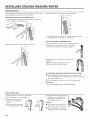
iNSTALLiNG STACKED WASHER/DRYER
Route Drain Hose
Proper routing of the drain hose avoids damage to your floor due to 3. Once the drain hose is in place, release the pliers.
water leakage. Read and follow these instructions.
Remove drain hose from the washer drum
1. Using locking pliers, squeeze hose clamp tabs together and
insert over the end of the drain hose.
C
4. The washer drain system can be installed using a floor drain,
wall standpipe, floor standpipe, or laundry tub.
2. Slide the drain hose onto the washer connection.
Laundry tub drain or standpipe drain
Connect the drain hose form to the corrugated drain hose.
Snap either end of the drain hose form to the drain
hose at the point where the corrugation begins.
Bend drain hose over drain hose form and snap
into place.
NOTE: Hose must not extend more than 1"
(25 mm) past the end of the U bend.
To keep drain water from going back into the washer:
Do not straighten the drain hose, do not force excess drain
hose into standpipe. Hose should be secure, but loose enough
to provide a gap for air.
m Do not lay excess hose on the bottom of the laundry tub.
Floor drain
You may need additional parts. See "Alternate Parts_'
Secure Drain Hose
1. Drape the power cord over the washer top.
2. Move the washer to its final location.
3. Place the drain hose in the "_
laundry tub or standpipe as
shown.
4. Secure the drain hose using ---
41/2""
the supplied beaded tie strap. (114 ram)
5. If the washer faucets and the drain
standpipe are recessed, put the
hooked end of the drain hose in
the standpipe as shown.
NOTES:
m Do not force excess drain hose
back into the rear of the washer.
m To avoid siphoning, do not seal
the drain hose into the standpipe.
18

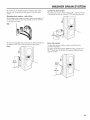
WASHER DRAIN SYSTEM
The washer can be installed using the standpipe drain system
(floor or wall), the laundry tub drain system, or the floor drain
system.
Standpipe drain system - wall or floor
The standpipe drain requires a minimum diameter standpipe of 2"
(50 ram). The minimum carry-away capacity can be no less than
10 gal. (38 L) per minute.
Wall
Laundry tub drain system
The laundry tub needs a minimum 20 gal. (76 L) capacity. The top
of the laundry tub must be at least 30" (762 mm) above the floor.
30"
(762 ram)
The top of the standpipe must be at least 30" (762 mm) high and
no higher than 96" (2.4 m) from the bottom of the washer.
Floor
m
30" rain.
Z
Floor drain system
The floor drain system requires a siphon break that may be
purchased separately.
The siphon break (Part Number 285834) must be a minimum of
28" (710 mm) from the bottom of the washer. Additional hoses
might be needed.
Syphon-
break _
28"
19

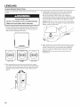
LEVELING
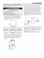
Leveling Stacked Washer/Dryer
Leveling your washer/dryer properly reduces excess noise and
vibration.
Excessive Weight Hazard
Use two or more people to move and install washer/dryer.
Failure to do so can result in back or other injury.
1. Remove cardboard from beneath washer/dryer. Place a level on
top edges of washer/dryer, checking each side and front. If not
level, tip washer/dryer and adjust feet up or down as shown in
Steps 3 and 4, repeating as necessary.
3=
If washer/dryer is not level, use a 9/16" or 14 mm openend
or adjustable wrench to turn jam nuts clockwise (as viewed
from above) on feet until they are about 1/2" (13 mm)
from the washer/dryer cabinet. Then turn the leveling foot
counterclockwise to lower the washer/dryer or clockwise to raise
the washer/dryer. Recheck levelness of washer/dryer and that all
four feet are firmly in contact with the floor. Repeat as needed.
HELPFUL TIP: You may want to prop up front of washer/dryer
about 4" (102 mm) with a wood block or similar object that will
support weight of washer/dryer.
\\
4. When washer/dryer is level and all four feet are firmly in contact
with the floor, use a 9/16" or 14 mm open-end or adjustable
wrench to turn jam nuts counterclockwise (as viewed from
above) on leveling feet tightly against washer/dryer cabinet.
HELPFUL TiP: You may want to prop washer/dryer with
wooden block.
Not Level LEVEL Not Level
2. Grip washer/dryer from top and rock back and forth, making
sure all four feet are firmly on floor. Repeat, rocking washer/dryer
from side to side. If washer/dryer rocks, go to Step 3 and adjust
leveling feet. If all four feet are in firm contact with floor, go to
Step 4.
20
La page est en cours de chargement...
La page est en cours de chargement...
La page est en cours de chargement...
La page est en cours de chargement...
La page est en cours de chargement...
La page est en cours de chargement...
La page est en cours de chargement...
La page est en cours de chargement...
La page est en cours de chargement...
La page est en cours de chargement...
La page est en cours de chargement...
La page est en cours de chargement...
La page est en cours de chargement...
La page est en cours de chargement...
La page est en cours de chargement...
La page est en cours de chargement...
La page est en cours de chargement...
La page est en cours de chargement...
La page est en cours de chargement...
La page est en cours de chargement...
La page est en cours de chargement...
La page est en cours de chargement...
La page est en cours de chargement...
La page est en cours de chargement...
La page est en cours de chargement...
La page est en cours de chargement...
La page est en cours de chargement...
La page est en cours de chargement...
La page est en cours de chargement...
La page est en cours de chargement...
La page est en cours de chargement...
La page est en cours de chargement...
La page est en cours de chargement...
La page est en cours de chargement...
La page est en cours de chargement...
La page est en cours de chargement...
La page est en cours de chargement...
La page est en cours de chargement...
La page est en cours de chargement...
La page est en cours de chargement...
La page est en cours de chargement...
La page est en cours de chargement...
La page est en cours de chargement...
La page est en cours de chargement...
-
 1
1
-
 2
2
-
 3
3
-
 4
4
-
 5
5
-
 6
6
-
 7
7
-
 8
8
-
 9
9
-
 10
10
-
 11
11
-
 12
12
-
 13
13
-
 14
14
-
 15
15
-
 16
16
-
 17
17
-
 18
18
-
 19
19
-
 20
20
-
 21
21
-
 22
22
-
 23
23
-
 24
24
-
 25
25
-
 26
26
-
 27
27
-
 28
28
-
 29
29
-
 30
30
-
 31
31
-
 32
32
-
 33
33
-
 34
34
-
 35
35
-
 36
36
-
 37
37
-
 38
38
-
 39
39
-
 40
40
-
 41
41
-
 42
42
-
 43
43
-
 44
44
-
 45
45
-
 46
46
-
 47
47
-
 48
48
-
 49
49
-
 50
50
-
 51
51
-
 52
52
-
 53
53
-
 54
54
-
 55
55
-
 56
56
-
 57
57
-
 58
58
-
 59
59
-
 60
60
-
 61
61
-
 62
62
-
 63
63
-
 64
64


Maytag MLE20PDBZW2 Guide d'installation
- Catégorie
- Machines à laver
- Taper
- Guide d'installation
- Ce manuel convient également à
dans d''autres langues
Documents connexes
-
Maytag MHN30PDAXW Manuel utilisateur
-
-
-
Maytag MLG20PDCWW0 Guide d'installation
-
-
Maytag MHN31PRAWW Installation Instructions Manual
-
-
-
Maytag MLG20PDBWW2 Guide d'installation
-
Whirlpool MGDE500VF1 Guide d'installation