
Important Safety Information .................3
Installation Instructions
........................... 4
Controls
.......................................................... 7
Controls and Operating Functions
...... 8
On Board Diagnostics
...............................9
Fault Codes
................................................. 10
Wiring Diagram
.......................................... 11
Testing the Thermostat
.......................... 12
Troubleshooting
........................................ 14
Limited Warranty
...................................... 15
Consumer Support
................................... 16
49-5000400 Rev. 1
08-19 GEA
THERMOSTAT
OWNER’S MANUAL
& INSTALLATION
INSTRUCTIONS
RARWT1W
RARWT1B
RARMEC1A
Write the model and serial numbers
here:
Model #
____________________
Serial # ____________________
You can find them on a label on the
thermostat.
GE is a trademark of the General Electric Company.
Manufactured under trademark license.
Single Zone RV

2
49-5000400 Rev. 1
THANK YOU FOR MAKING GE
APPLIANCES A PART OF YOUR RV.
Whether you grew up with GE Appliances, or this is
your first, we’re happy to have you in the family.
We take pride in the craftsmanship, innovation and
design that goes into every GE Appliances product,
and we think you will too. Among other things,
registration of your appliance ensures that we can
deliver important product information and warranty
details when you need them.

49-5000400 Rev. 1 3
IMPORTANT SAFETY INFORMATION
READ ALL INSTRUCTIONS BEFORE USING THE APPLIANCE
WARNING
FIRE AND SHOCK HAZARD
Ŷ
Always turn off power at the main power supply
before installing, cleaning or removing the
thermostat.
Ŷ
Do not use on voltages over 12 VDC. Higher
voltages will damage the thermostat and could cause
shock or fire hazards.
Ŷ
All wiring must conform to local and national
electrical and building codes.
Ŷ
Use this thermostat only as described in this manual.
Specifications
Electrical Rating:
12 VDC (Operating Range from 10.5 VDC - 14 VDC)
Changing Units Between Fahrenheit (°F) and Celsius (°C):
Simultaneously hold the Temp +/- buttons for 2 seconds.
Operating temperature Range:
0°F-115°F (-18°C-46°C)
Cooling Range:
60°F-85°F (15°C-30°C)
Heating Range
40°F-85°F (5°C-30°C)
Accuracy:
± 1°F (± 0.5°C)
Wall Thermostat Terminations:
0V (GND), Signal (COMMS), +12VDC
Wiring:
12 VDC Thermostat: Recommend AWG20 solid 3 copper wire
12 VDC Main Control: Recommend AWG18 stranded 2
copper wire
120 VAC Main Control: Recommend AWG12 solid copper
wire

4
49-5000400 Rev. 1
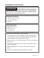
WARNING
ELECTRICAL SHock Hazard
Turn off power by removing the fuse or switching the
appropriate circuit breaker to the OFF position before
removing the existing thermostat.
Package Contents
Ŷ
Thermostat on cover
Ŷ
Thermostat base
Ŷ
Screws
Tools Required
Ŷ
Drill with 1/8” bit
Ŷ
Ballpoint Pen
Ŷ
Screwdriver
To Remove Existing Thermostat
1. Turn off power to the heating and cooling system by
removing the fuse or switching off the appropriate
circuit breaker (120 VAC and 12VDC)
2. Remove cover of old thermostat. This should expose
the wires.
3. Label the existing wires with the wire labels before
removing wires.
4. After labeling wires, remove wires from terminal
block.
5. Remove existing thermostat base from wall.
Installation Instructions

49-5000400 Rev. 1 5
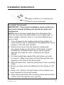
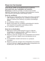
Installation Instructions
To Install Thermostat
IMPORTANT: Thermostat installation must conform to
local and national building and electrical codes and
ordinances.
NOTE: Mount the thermostat about five feet above the
floor. Do not mount the thermostat on an outside wall, in
direct sunlight, behind a door or in an area affected by a
vent or duct.
1. Turn off power to the heating and cooling system by
removing the fuse or switching off the appropriate circuit
breaker. (120 VAC and 12VDC).
2. Remove the cover from the base by undoing the
two plastic snaps on the bottom of the base. A small
screwdriver or ballpoint pen can be used to gently
depress one snap at a time. (reference the figure
above).
3. Put thermostat base against the wall where you plan
to mount it. Make sure wires will feed through the wire
opening in the base of the thermostat.
4. With the base level, mark the placement of the mounting
holes.
5 Ensure no other wires are affected by the drilling of 1/8”
holes.
6. Using a 1/8” drill bit, drill pilot holes in the locations you
have marked for the wood screws.
8. Align thermostat base with mounting holes and feed the
control wires through the wire opening.
Apply screwdriver or ballpoint pen
here to open thermostat

6
49-5000400 Rev. 1
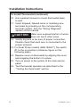
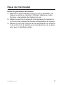
Installation Instructions
To Install Thermostat (continued)
10.
Use supplied screws to mount thermostat base
to wall.
11. Insert stripped, labeled wires in matching wire
terminals by pressing on the corresponding
terminal contact. See the “Wiring Diagrams”
section of this manual.
CAUTION
Make sure exposed portion of wires
does not touch other wires.
12. Gently tug wire to be sure of proper connection.
Double check that each wire is connected to the
proper terminal.
13. For Heat Pump models (ARH15AAC*), flip switch
#1 to the on position (reference figure on the
following page).
14. Replace cover on thermostat by aligning the cover
and snapping the bottom it in place.
15. Turn on power to the system at the main service
panel.
16. Test thermostat operation as described in the
“Testing the thermostat” section.

49-5000400 Rev. 1 7
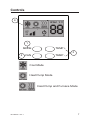
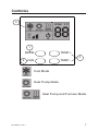
Controls
1
2
4
MODE
FAN
TEMP +
TEMP -
3
Cool Mode
Heat Pump Mode
Heat Pump and Furnace Mode

8
49-5000400 Rev. 1
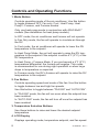
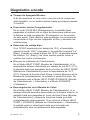
Controls and Operating Functions
1. Mode Button
Controls operating mode of the air conditoner. Use this button
to toggle between OFF, Fan only, Cool, Heat Pump, Heat
Pump + Furnace, and Furnace modes.
Only use heat pump mode in conjunction with ARH15AAC*
models (See installation for heat pump models).
In OFF mode, the air conditioner and furnace will not operate.
In Fan Only mode, the fan will operate to circulate air through
the RV.
In Cool mode, the air conditoner will operate to lower the RV
temperature to the setpoint.
In Heat Pump Mode, the unit will operate to raise the RV tem-
perature to the setpoint if the setpoint is within 4°F (2°C) of the
RV temperature.
In Heat Pump + Furnace Mode, If you are beyond a 4°F (2°C)
WHPSHUDWXUHGLႇHUHQWLDOWKHIXUQDFHZLOOHQJDJH7KLVPRGH
is recommended for use during night operation or when large
drops in temperature re expected.
In Furnace mode, the RV’s furnace will operate to raise the RV
temperature to the setpoint.
2. Fan Button
Controls operating speed and mode of the fan. Use this button
to toggle between low and high fan speeds.
Use this button to toggle between “FAN ON” and “AUTO FAN”.
In “FAN ON” mode, the fan will run even when the setpoint has
been reached.
,Q³$872)$1´PRGHWKHIDQZLOOWXUQRႇRQFHWKHVHWSRLQWKDV
been reached.
3. Temperature Selection Buttons
Use these buttons to raise and lower the desired setpoint
temperature.
4. LCD Display
Displays operating mode, temperature setpoint, and fan speed.

49-5000400 Rev. 1 9
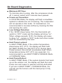
On Board Diagnostics
Ŷ
Minimum Off Time:
To minimize short cycling, after the compressor shuts
off, it cannot restart until 3 minutes have passed.
Ŷ
Freeze-up Prevention:
In COOLING Mode, the display will flash a snowflake
symbol to indicate the coil is freezing. The compressor
will not operate in this mode. To troubleshoot, it is
recommended to increase airflow by cleaning the filter
and opening the vents.
Ŷ
Low Voltage Detection:
If the 12VDC drops below 10.5, the thermostat will
switch to “OFF” mode and the display will show “Lo”.
When voltage exceeds 10.5V, the display will cease
to show “Lo” , remain in “OFF” mode and other modes
must be reselected by the user.
Ŷ
Heat Pump Lockout:
In HEAT PUMP Mode, if the outdoor temperature
drops below 32°F (0°C), the display will flash both
the HEAT PUMP icon and 32°F (0°C). During Heat-
Pump Lockout, the unit will not produce heat. When
temperatures below 32°F (0°C) are expected, it is
recommended to use HEAT PUMP+FURNACE Mode
or FURNACE Mode.
Ŷ
Heat Pump Defrost:
In HEAT PUMP Mode, if the system detects frost build
up on the outdoor coil, the display will flash the Heat
Pump icon and cease to operate until fully defrosted.
If you are in HEAT PUMP + FURNACE Mode, the
unit will use the furnace until the heat pump is fully
defrosted.

10
49-5000400 Rev. 1
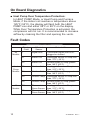
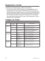
On Board Diagnostics
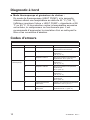
Fault Codes
Ŷ
Heat Pump Over Temperature Protection:
In HEAT PUMP Mode, or Heat Pump and Furnace
Mode, if the indoor coil reaches a temperature above
125°F (52°C), the display will flash both the HEAT
PUMP icon and either 99°F or 99°C on the display.
While Over Temperature Protection is activated, the
compressor will not run. It is recommended to increase
airflow by cleaning the filter and opening the vents.
Fault Codes
Display
Code
$ႇHFWHG
Sensor
Potential Cause
All
Models
-- Signal Wire Thermostat Signal Wire is un-
plugged or shorted
F1 Indoor Coil Unplugged Sensor or Temp less
than -31°F (-35°C)
F2 Indoor Coil Shorted Wires or Temp greater
than 149°F (65°C)
Heat
Pump
Models
F3 Outdoor Coil Unplugged Sensor or Temp less
than -31°F (-35°C)
F4 Outdoor Coil Shorted Wires or Temp greater
than 149°F (65°C)
F5 Outdoor Temp Unplugged Sensor or Temp less
than -31°F (-35°C)
F6 Outdoor Temp Shorted Wires or Temp greater
than 149°F (65°C)
All
Models
F7 Thermostat
Room Sensor
Unplugged Sensor or Temp less
than -31°F (-35°C)
F8 Thermostat
Room Sensor
Shorted Wires or Temp greater
than 149°F (65°C)

49-5000400 Rev. 1 11
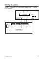
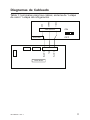
Wiring Diagrams
Table 1: terminals for three wires 1-stage heat / 1-stage
cool system.
T-stat Terminal
Thermostat
Main Board
GND
COMMS
+12VDC
Black/White
Yellow
Red/White
1234
ON
OFF

12
49-5000400 Rev. 1
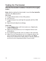
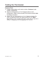
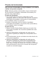
Once the thermostat is installed, it should be thoroughly
tested.
Note: Before testing the thermostat, move the Fan Auto/On
switch to the Auto position.
Fan Test
1.
Toggle Mode button to Fan ON position.
2. Fan turns on.
3. Toggle between low and high fan speeds with the FAN
button.
4.
Speed should adjust accordingly
Cool Test
1.
Toggle Mode button until Cool mode is on. Cool mode
screen is displayed.
2.
Adjust set temperature so it is 5 degrees below room
temperature.
3.
Air conditioning should come on within a few seconds.
4. Adjust the set temperature so it is 2 degrees above the
room temperature and the A/C should turn off. Note:
There is a 3 minute time delay and a 3 minute minimum
run time for the compressor when it turns on/off.
Testing the Thermostat

49-5000400 Rev. 1 13
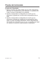
Testing the Thermostat
Furnace Test
1.
Toggle mode button until mode is active. Furnace mode
screen is displayed.
2.
Adjust set temperature so it is 5 degrees above room
temperature. Within a few seconds, the furnace should initiate
its startup procedure.
3.
Adjust the set temperature so it is 2 degrees below the
room temperature and the heat should turn off. Note:
Depending on the model of furnace used, there may be a
delay in engaging and disengaging the furnace.

14
49-5000400 Rev. 1
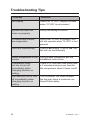
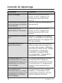
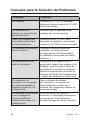
Troubleshooting Tips
Problem Solution
No Display Check for 12 VDC; display is blank
when 12 VDC is not present
System fan does not
come on properly
Verify that wiring is correct
All thermostat buttons
are inoperative
Verify that 12 VDC is present; unit
will not operate when 12 VDC is not
present
Fan runs continuously Check Fan setting. If set to ON, the
fan will run continuously
Room temperature is not
correct
Verify proper installation per the
installation instructions
Compressor does
QRWUXQRUWXUQRႇ
immediately when
changing function or
setting.
There is a 3 minutes time delay and
a 3 minutes minimum run time for
WKHFRPSUHVVRUZKHQLWWXUQVRQRႇ
Fan does not run or turn
RႇLPPHGLDWHO\ZKHQ
changing funciton or
setting
This is normal. On some models,
the fan may have a minimum run
WLPHRႇWLPHGHOD\

49-5000400 Rev. 1 15
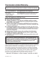
Thermostat Limited Warranty
For The Period Of: GE Appliances Will Replace:
Two Years Full Replacement of the thermostat which fails
From the date of the due to a defect in materials or workmanship.
original purchase
What GE Appliances Will Not Cover:
Ŷ
Service trips to your location.
Ŷ
Improper installation. If you have an installation problem, contact
your installer. You are responsible for providing adequate electrical
connections to the product.
Ŷ
Failure of the product resulting from modifications to the product or
due to unreasonable use, including failure to provide reasonable and
necessary maintenance.
Ŷ
In commercial locations, labor necessary to move the unit, after it has
been initially installed, to a location where it is accessible for service by
an individual technician; or, if the instructions included in this manual
have been disregarded.
Ŷ
Replacement of location fuses or the resetting of circuit breakers.
Ŷ
Damage to the product caused by improper power supply voltage,
accident, fire, floods or acts of God.
Ŷ
Incidental or consequential damage caused by possible defects with
this thermostat.
Staple your receipt here.
Proof of the original purchase date is needed to validate the warranty.
This limited warranty is extended to the original purchaser and any succeeding
owner for products purchased for use within the USA and Canada. In Alaska, the
limited warranty excludes the cost of shipping or service calls to your site.
Some states or provinces do not allow the exclusion or limitation of incidental
or consequential damages. This limited warranty gives you specific legal rights,
and you may also have other rights which vary from state to state or province
to province. To know what your legal rights are, consult your local, state or
provincial consumer affairs office or your state’s Attorney General.
Warrantor: GE Appliance, a Haier company. Louisville, KY 40225
EXCLUSION OF IMPLIED WARRANTIES—Your sole and exclusive
remedy is product exchange as provided in this Limited Warranty. Any
implied warranties, including the implied warranties of merchantability
or fitness for a particular purpose, are limited to one year or the
shortest period allowed by law.

16
49-5000400 Rev. 1
GE Appliances Website
Have a question or need assistance with your appliance? Try the GE
Appliances Website 24 hours a day, any day of the year! You can also
shop for more great GE Appliances products and take advantage of all
our on-line support services designed for your convenience. In the US:
GEAppliances.com
Register Your Appliance
Register your new appliance on-line at your convenience! Timely product
registration will allow for enhanced communication and prompt service
under the terms of your warranty, should the need arise. You may also
mail in the pre-printed registration card included in the packing material. In
the US: GEAppliances.com/register
Schedule Service
Call 1-877-540-7837 during normal business hours.
Extended Warranties
Purchase a GE Appliances extended warranty and learn about special
discounts that are available while your warranty is still in effect. You can
purchase it on-line anytime. GE Appliances Services will still be there after
your warranty expires. In the US: GEAppliances.com/extended-warranty
or call 800.626.2224 during normal business hours.
Remote Connectivity
For assistance with wireless network connectivity (for models with remote
enable),
visit our website at GEAppliances.com/connected-home-smart-
appliances or call 800.220.6899 in the US.
Parts and Accessories
Individuals qualified to service their own appliances can have parts or
accessories sent directly to their homes
(VISA, MasterCard and Discover cards are accepted). Order on-line today
24 hours every day.
In the US: GEApplianceparts.com or by phone at 877.959.8688 during
normal business hours.
Instructions contained in this manual cover procedures to be
performed by any user. Other servicing generally should be referred
to qualified service personnel. Caution must be exercised, since
improper servicing may cause unsafe operation.
Contact Us
If you are not satisfied with the service you receive from GE Appliances,
contact us on our Website with all the details including your phone
number, or write to:
General Manager, Customer Relations | GE Appliances, Appliance Park |
Louisville, KY 40225
GEAppliances.com/contact
Consumer Support

49-5000400 Rev. 1
08-19 GEA
THERMOSTAT
Manuel Du Propriétaire
Et Instructions
D’installation
RARWT1W
RARWT1B
RARMEC1A
GE est une marque déposée de General Electric
Company. Fabriqué sous licence de marque.
Écrivez le modèle et les numéros de série ici
Modèle # ___________________
En série # __________________
Vous pouvez les trouver sur une étiquette
sur le thermostat.
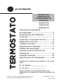
Renseignements Importants
Concernant La Sécurit
...............................3
Instructions d’installation
....................... 4
Commandes
..................................................7
Commandes et fonctions de
fonctionnement
.......................................... 8
Diagnostic à bord
.......................................9
Codes d’erreurs
.........................................10
Schémas de câblage
................................. 11
Essai du thermostat
................................. 12
Conseils de dépannage
..........................14
Garantie Limitée
........................................ 15
Soutien au consommateur
..................... 16

2
49-5000400 Rev. 1
NOUS VOUS REMERCIONS D’ACCUEILLIR GE
APPLIANCES CHEZ VOUS RV
Que vous ayez grandi avec GE Appliances ou
qu’il s’agisse de votre première acquisition, nous
sommes heureux de vous accueillir dans notre
famille.
Nous sommes fiers du savoir-faire, de l’innovation
et de l’esthétique qui composent chaque appareil
GE Appliances, et nous pensons que vous le serez
aussi. Dans cette optique, nous vous rappelons
que l’enregistrement de votre électroménager
vous assure la communication de renseignements
importants sur le produit et la garantie lorsque vous
en avez besoin.
Enregistrez votre électroménager GE en ligne dès
maintenant. Des sites Web et des numéros de
téléphone utiles figurent dans la section Soutien au
consommateur de ce manuel d’utilisation.

49-5000400 Rev. 1 3
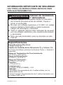
RENSEIGNEMENTS IMPORTANTS
CONCERNANT LA SÉCURITÉ
LISEZ TOUTES LES INSTRUCTIONS AVANT D’UTILISER CET
APPAREIL.
AVERTISSEMENT
RISQUE D’INCENDIE ET
D’ÉLECTROCUTION
Ŷ
Mettez toujours l’alimentation électrique hors tension
depuis la source d’alimentation électrique principale avant
d’installer, de nettoyer ou de retirer le thermostat.
Ŷ
N’utilisez pas des tensions supérieures à 12 VCC. Des
tensions plus élevées endommageront le thermostat en
plus de représenter un risque d’électrocution ou d’incendie.
Ŷ
Tout le câblage doit être conforme aux Codes de
l’électricité et du bâtiment locaux et nationaux.
Ŷ
Utilisez ce thermostat aux seules fins décrites dans ce
manuel.
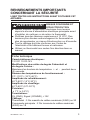
Fiche technique
Caractéristiques électriques :
12 VCC 10.5V-14V
0RGL¿FDWLRQVGHVXQLWpVGHGHJUpV)DKUHQKHLWHW
GHGHJUpV&HOVLXV
Maintenez les boutons de température + et - pendant deux
(2) seconds.
Gamme des températures de fonctionnement :
0°F-115°F (-18°C-46°C)
Amplitude de refroidissement :
60°F-85°F (15°C-30°C)
$PSOLWXGHGHFKDXIIDJH
40°F-85°F (5°C-30°C)
Précision:
± 1°F (± 0.5°C)
Terminations:
0V (GND), Signal (COMMS), +12V
&kEODJH
Thermostat : 3 fils massifs de calibre américain (AWG) no 20
Commande principale : 2 fils toronnés de calibre américain
(AWG) no 18

4
49-5000400 Rev. 1
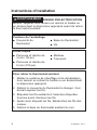
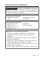
Instructions d’installation
AVERTISSEMENT
RISQUE D’ÉLECTROCUTION
Mettez l’appareil hors tension en retirant le fusible ou
en déclenchant le disjoncteur approprié avant de retirer
le thermostat existant.
&RQWHQXGHO¶HPEDOODJH
Ŷ&RXYHUFOHGX
thermostat
Ŷ%DVHGXWKHUPRVWDW
Ŷ9LV
Outils requis
Ŷ3HUFHXVHHWPqFKHGH
3 mm (1/8 po)
Ŷ3HUFHXVHHWPqFKHGH
5 mm (3/16 po)
Ŷ0DUWHDX
Ŷ7RXUQHYLV
Pour retirer le thermostat existant
1. Mettez le système de chauffage et de climatisation
hors tension en retirant le fusible ou en déclenchant
le disjoncteur approprié.
2. Retirez le couvercle du thermostat à changer. Ceci
devrait exposer les fils.
3. Étiquetez les fils existants à l’aide des étiquettes
fournies avant d’enlever les fils.
4. Après avoir étiqueté les fils, débranchez les fils des
cosses.
5. Retirez la base du thermostat existant du mur.
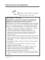
La page est en cours de chargement...
La page est en cours de chargement...
La page est en cours de chargement...
La page est en cours de chargement...
La page est en cours de chargement...
La page est en cours de chargement...
La page est en cours de chargement...
La page est en cours de chargement...
La page est en cours de chargement...
La page est en cours de chargement...
La page est en cours de chargement...
La page est en cours de chargement...
La page est en cours de chargement...
La page est en cours de chargement...
La page est en cours de chargement...
La page est en cours de chargement...
La page est en cours de chargement...
La page est en cours de chargement...
La page est en cours de chargement...
La page est en cours de chargement...
La page est en cours de chargement...
La page est en cours de chargement...
La page est en cours de chargement...
La page est en cours de chargement...
La page est en cours de chargement...
La page est en cours de chargement...
La page est en cours de chargement...
La page est en cours de chargement...
-
 1
1
-
 2
2
-
 3
3
-
 4
4
-
 5
5
-
 6
6
-
 7
7
-
 8
8
-
 9
9
-
 10
10
-
 11
11
-
 12
12
-
 13
13
-
 14
14
-
 15
15
-
 16
16
-
 17
17
-
 18
18
-
 19
19
-
 20
20
-
 21
21
-
 22
22
-
 23
23
-
 24
24
-
 25
25
-
 26
26
-
 27
27
-
 28
28
-
 29
29
-
 30
30
-
 31
31
-
 32
32
-
 33
33
-
 34
34
-
 35
35
-
 36
36
-
 37
37
-
 38
38
-
 39
39
-
 40
40
-
 41
41
-
 42
42
-
 43
43
-
 44
44
-
 45
45
-
 46
46
-
 47
47
-
 48
48


GE RARWT1W Mode d'emploi
- Catégorie
- Composants de dispositif de sécurité
- Taper
- Mode d'emploi
dans d''autres langues
- English: GE RARWT1W User guide
- español: GE RARWT1W Guía del usuario
Documents connexes
-
GE AH11E09D3B Mode d'emploi
-
GE RARMN1A Mode d'emploi
-
-
GE AZ91H18E2E Le manuel du propriétaire
-
-
-
GE AZ95H12EAC Mode d'emploi
-
GE Zoneline AZ91H18E3C Le manuel du propriétaire
-
GE AZ91H18D3C Le manuel du propriétaire
