Schneider Electric Enclosed Altistart 22 Solid State Reduced Voltage Combination Motor Controller Instruction Sheet
- Taper
- Instruction Sheet

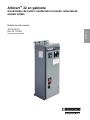
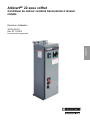
Enclosed Altistart™ 22
Solid State Reduced Voltage Combination Motor Controller
Altistart™ 22 en gabinete
Controlador de motor combinado a tensión reducida de estado sólido
AltistartMC 22 sous coffret
Contrôleur de moteur combiné transistorisé à tension réduite
Instruction Bulletin
Boletín de instrucciones
Directives d'utilisation
30072-453-26
Rev. 03, 12/2012
Retain for Future Use.
Conservar para uso futuro.
À conserver pour usage ultérieur.
™


30072-453-26 Table of Contents
Rev. 03, 12/2012 Contenido
Table des matières
© 2012 Schneider Electric All Rights Reserved / Reservados todos los derechos / Tous droits réservés iii
Enclosed Altistart™ 22
Solid State Reduced Voltage Combination Motor Controller
Altistart™ 22 en gabinete
Controlador de motor combinado a tensión reducida de estado sólido
AltistartMC 22 sous coffret
Contrôleur de moteur combiné transistorisé à tension réduite
ENGLISHESPAÑOLFRANÇAIS

Table of Contents 30072-453-26
Contenido Rev. 03, 12/2012
Table des matières
© 2012 Schneider Electric All Rights Reserved / Reservados todos los derechos / Tous droits réservésiv

Enclosed Altistart™ 22
Solid-State Reduced Voltage Combination Motor Controller
Instruction Bulletin
30072-453-26
Rev. 03, 12/2012
Retain for future use.
ENGLISH
™

ENGLISH

30072-453-26 Enclosed Altistart™ 22 Motor Controller
Rev. 03, 12/2012 Contents
© 2012 Schneider Electric All Rights Reserved 3-EN
ENGLISH
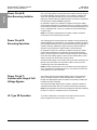
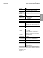
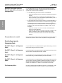
Hazard Categories and Special Symbols..................................................... 6
SECTION 1: INTRODUCTION AND TECHNICAL CHARACTERISTICS ................................................................................ 7
Product Overview......................................................................................... 7
Standard Features .......................................................................................7
About this Document.................................................................................... 7
Terminology ................................................................................................. 8
Before You Begin......................................................................................... 8
Nameplate Identification............................................................................. 10
Catalog Number Description...................................................................... 10
Technical Characteristics........................................................................... 13
Short-Circuit Ratings.................................................................................. 17
Technical Specifications............................................................................. 18
SECTION 2: RECEIVING, HANDLING, AND STORING ........................................................................................................ 21
Receiving and Preliminary Inspection........................................................ 21
Storing the Equipment................................................................................ 21
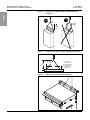
Unpacking the Controller............................................................................ 22
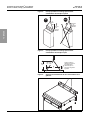
Wall-Mounted Units ............................................................................. 22
Floor-Mounted Units ............................................................................22
Lifting the Controller................................................................................... 23
Wall-Mounted Controllers ....................................................................23
Floor-Mounted Controllers ...................................................................23
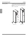
Positioning the Controller........................................................................... 25
SECTION 3: INSTALLATION AND START-UP .................................................................................................................... 27
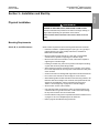
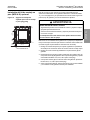
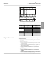
Physical Installation.................................................................................... 27
Mounting Requirements ...................................................................... 27
Size A, B, C, and D Enclosures ..................................................... 27
Size E, F, and G Enclosures ..........................................................28
Spacing Requirements ........................................................................ 29
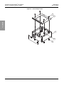
EZM Mounting Channel ....................................................................... 30
Seismic Qualification Mounting Criteria ............................................... 32
Weights ............................................................................................... 34
Center of Gravity ................................................................................. 36
Trilingual Legend Plate Kit ..................................................................38
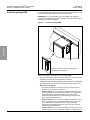
Installing the Optional Floor-Mounting Kit (MOD A10) ........................39
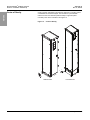
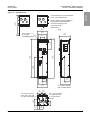
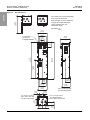
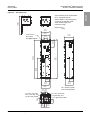
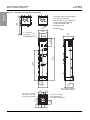
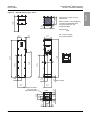
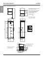
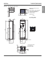
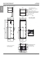
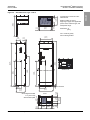
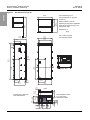
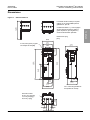
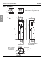
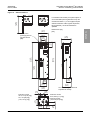
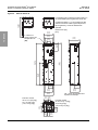
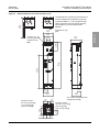
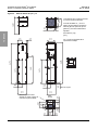
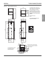
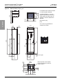
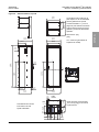
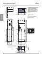
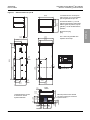
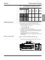
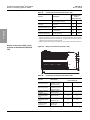
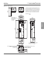
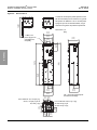
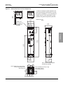
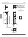
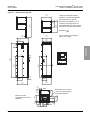
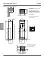
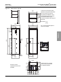
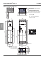
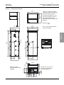
Dimensions ................................................................................................ 40
Electrical Installation .................................................................................. 51
General Wiring Practices ..................................................................... 51
Input Wiring ......................................................................................... 51
Grounding ............................................................................................ 52
Output Wiring ......................................................................................52
Wire Routing and Interconnection ....................................................... 53
Wire Class .....................................................................................53
EMI Class ......................................................................................53
Voltage Class .................................................................................53
Wiring Methods .............................................................................. 57
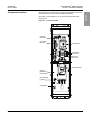
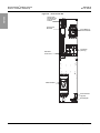
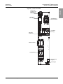
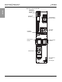
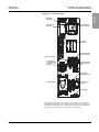
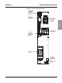
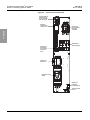
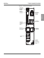
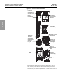
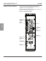
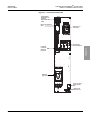
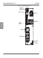
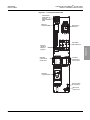
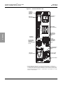
Component Locations .........................................................................59
Power Wiring ....................................................................................... 64
Control Wiring ...................................................................................... 70
Shunt Trip (B05) ............................................................................70
Shunt Trip (S05) and Other Power Options (N05, R05, Y05) ........ 71
Initial Start-Up Procedure........................................................................... 72
ATS22 Soft Starter Factory Settings ................................................... 76
Programming Access with Omit Keypad Option (U10) or
UL Type 3R Enclosure (H03) .............................................................. 76

Enclosed Altistart™ 22 Motor Controller 30072-453-26
Contents Rev. 03, 12/2012
© 2012 Schneider Electric All Rights Reserved4-EN
ENGLISH
Adjusting the PowerPact Motor Circuit Protector Trip Setting .............78
Style 22T ........................................................................................78
Style 22U .......................................................................................79
Power Fuse Recommendations Style 22F ..........................................81
Overload Relay Adjustment .................................................................82
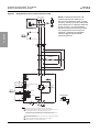
SECTION 4: CIRCUIT DESCRIPTIONS .....................................................................................................................85
Precautions ................................................................................................85
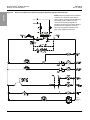
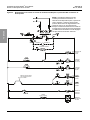
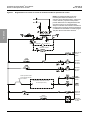
Power Circuit B: Basic Shunt Trip ..............................................................85
Power Circuit S: Full-Featured Shunt Trip..................................................85
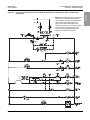
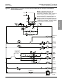
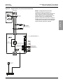
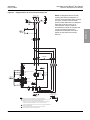
Power Circuit N: Non-Reversing Isolation ..................................................86
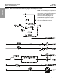
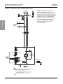
Power Circuit R: Reversing Operation .......................................................86
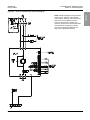
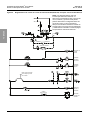
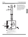
Power Circuit Y: Isolation with Integral Full-Voltage Bypass......................86
UL Type 3R Operation ...............................................................................86
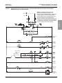
Control Options ..........................................................................................87
Mod A06: Start-Stop Pushbuttons .......................................................87
Mod B06: Forward-Off-Reverse Selector Switch .................................87
Mod C06: Hand-Off-Auto Selector Switch ...........................................87
Mod D06: Stop-Run Selector Switch ...................................................87
Mod E06: Hand-Auto Selector Switch and Start-Stop Pushbuttons ....87
No Control Operators ...........................................................................88
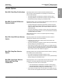
Pilot Light Cluster Options..........................................................................89
Mod A07: Pilot Light Cluster #1 ...........................................................89
Mod B07: Pilot Light Cluster #2 ...........................................................89
Mod C07: Pilot Light Cluster #3 ...........................................................89
Mod D07: Pilot Light Cluster #4 ...........................................................89
No Pilot Lights ......................................................................................89
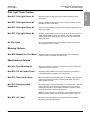
Metering Options ........................................................................................89
Mod B08: Elapsed Run Time Meter .....................................................89
Miscellaneous Options ...............................................................................89
Mod A10: Floor Mounting Kit ...............................................................89
Mod B10: 150 VA Control Power .........................................................89
Mod C10: Power Up On Delay ............................................................89
Mod D10: Emergency Stop Pushbutton ..............................................89
Mod E10: cUL Label ............................................................................89
Mod F10: Auxiliary Contact for Run Mode Annunciation .....................90
Power Circuit B05 ..........................................................................90
Power Circuits S05, N05, R05, and Y05 ........................................90
Mod G10: Auxiliary Contact for Bypass Run Indication .......................90
Mod H10: Auxiliary Contact for Auto Mode Annunciation ....................90
Power Circuit B05 ..........................................................................90
Power Circuits S05, N05, and Y05 ................................................90
Mod J10: Auxiliary Contact for Trip Condition Annunciation ................90
Power Circuit B05 ..........................................................................90
Power Circuits S05, N05, R05, and Y05 ........................................90
Mod L10: Customer Engraved Nameplates .........................................90
Mod M10: Ten Additional Unwired Terminal Points .............................90
Mod P10: Permanent Wire Markers ....................................................90
Mod R10: Transient Voltage Surge Protection ....................................90
Mod U10: Omit Door-Mounted Keypad Display ...................................91
Mod X10: 50 °C Operation ...................................................................91
Mod Z10: Service Entrance Rating ......................................................91
Mod Y10: Seismic Qualified .................................................................91
Mod 610: High Interrupting Rating .......................................................91
Mod 910: ARRA Option .......................................................................91
Engineered To Order Electrical Diagrams................................................102

30072-453-26 Enclosed Altistart™ 22 Motor Controller
Rev. 03, 12/2012 Contents
© 2012 Schneider Electric All Rights Reserved 5-EN
ENGLISH
SECTION 5: MAINTENANCE .................................................................................................................. 103
Precautions .............................................................................................. 103
External Signs of Damage ....................................................................... 105
Diagnostic Codes..................................................................................... 105
Technical Support .................................................................................... 105
Enclosed 22 Troubleshooting Sheet .................................................106
ATS22 Fan Replacement......................................................................... 107
Renewable Parts...................................................................................... 108

Enclosed Altistart™ 22 Motor Controller 30072-453-26
Contents Rev. 03, 12/2012
© 2012 Schneider Electric All Rights Reserved6-EN
ENGLISH
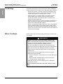
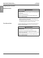
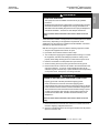
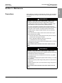
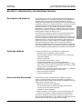
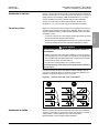
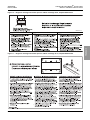
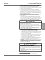
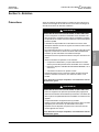
Hazard Categories and Special
Symbols
Read these instructions carefully and look at the equipment to become
familiar with the device before trying to install, operate, service, or maintain
it. The following special messages may appear throughout this bulletin or on
the equipment to warn of hazards or to call attention to information that
clarifies or simplifies a procedure.
The addition of either symbol to a “Danger” or “Warning” safety label
indicates that an electrical hazard exists which will result in personal injury if
the instructions are not followed.
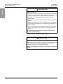
This is the safety alert symbol. It is used to alert you to personal injury
hazards. Obey all safety messages that follow this symbol to avoid possible
injury or death.
NOTE: Provides additional information to clarify or simplify a procedure.
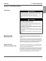
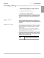
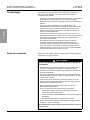
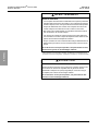
Please Note Electrical equipment should be installed, operated, serviced, and maintained
only by qualified personnel. No responsibility is assumed by Schneider
Electric for any consequences arising out of the use of this material.
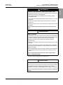
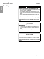
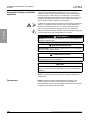
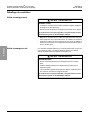
DANGER
DANGER indicates a hazardous situation which, if not avoided, will result
in death or serious injury.
WARNING
WARNING indicates a hazardous situation which, if not avoided, can
result in death or serious injury.
CAUTION
CAUTION indicates a hazardous situation which, if not avoided, can
result in minor or moderate injury.
NOTIC
E
NOTICE is used to address practices not related to physical injury. The
safety alert symbol is not used with this signal word.

30072-453-26 Enclosed Altistart™ 22 Motor Controller
Rev. 03, 12/2012 Section 1—Introduction and Technical Characteristics
© 2012 Schneider Electric All Rights Reserved 7-EN
ENGLISH
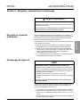
Section 1—Introduction and Technical Characteristics
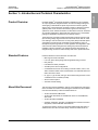
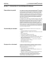
Product Overview Enclosed Altistart™ 22 (ATS22) solid-state combination motor controllers
are a pre-engineered, integrated solution for reduced voltage starting and
soft stopping of standard three-phase asynchronous induction (squirrel
cage) motors. The Enclosed 22 controllers consist of a disconnect means,
optional power circuit contactors for isolation, bypass, and reversing
operations, and an ATS22 soft starter in a stand-alone enclosure. Enclosed
22 controllers integrate the ATS22 soft start technology into a combination
package for application requirements up to 500 hp at 575 V.
The Enclosed 22 controller provides the benefits of reduced current inrush
(and resulting voltage sag) and reduced mechanical shocks that can result
from starting a motor across the line. A six thyristor (SCR) solid-state power
configuration provides smooth acceleration and deceleration control of
three-phase squirrel cage motors. Control algorithms are integrated to help
ensure smooth rotation throughout the starting ramp without mechanical
instability at the end of starting. The ATS22 soft starter also features an
integral shorting contactor to reduce steady state motor operational losses.
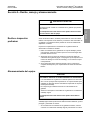
Standard Features Features standard on the Enclosed 22 controllers are:
•Mid-range enclosed soft starter
•Low cost, space-saving design with integrated shorting contactor
•Easy start-up
•Full starter and motor protection
•Versatile power circuit configurations
•Coordinated short circuit current rating of 100 kA at 208 V, 240 V, and
480 V and 50 kA at 600 V with circuit breakers, and 100 kA at 208 V and
600 V with Class J fuses
•UL Type 1, Type 12/12K, and Type 3R enclosure ratings and UL Listed
combination motor controller (UL 508)
•Service entrance option
•Automatic remote starting
About this Document This document contains installation, start-up, and maintenance instructions
for the Enclosed 22 controller. The following documentation is also available
from the technical library at www.schneider-electric.us:
•ATS22 User Manual, BBV51330
•ATS22 Quick Start Guide, S1A10388 and Annex for UL508 Markets,
S1A14738
•ATS22 CD-ROM, VW3A8200
•Handling, Installation, Operation, and Maintenance of Electrical Control
Equipment, Instruction Bulletin 30072-200-50
To replace documents, contact your local Schneider Electric field office or
download them from the Technical Library at www.schneider-electric.us.

Enclosed Altistart™ 22 Motor Controller 30072-453-26
Section 1—Introduction and Technical Characteristics Rev. 03, 12/2012
© 2012 Schneider Electric All Rights Reserved8-EN
ENGLISH
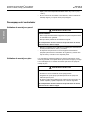
Terminology The following terminology is used in this instruction bulletin to distinguish
between the Enclosed 22 controller and the ATS22 soft starter component:
•Enclosed 22 controller, or controller, refers to the combination of the
ATS22 soft starter, enclosure, and the power and control circuits that
comprise the Enclosed 22 combination motor controller.
•ATS22 soft starter, or soft starter, refers to the ATS22 solid-state
reduced voltage motor controllers used as a component in the
Enclosed 22 controller. The ATS22 soft starter is described in the
ATS22 User Manual, BBV51330.
•Shorting contactor refers to the internal contactor(s) in the ATS22 soft
starter. The shorting contactor closes during full speed operation to
reduce losses under steady state operation.
•Bypass, or integral bypass starter, refers to the optional, integrated full
voltage combination starter in the enclosed ATS22 controller (power
circuit option Y05). When provided, the integral bypass starter may be
used to start and run the motor in the unlikely event that the ATS22 soft
starter becomes inoperable.
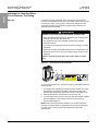
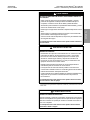
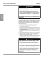
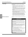
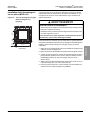
Before You Begin Read and follow these precautions before performing any procedure with
this controller.
.
DANGER
HAZARD OF ELECTRIC SHOCK, EXPLOSION, OR ARC FLASH
• Read and understand this manual before installing or operating the
Enclosed 22 controller. Installation, adjustment, repair, and
maintenance must be performed by qualified personnel.
• The user is responsible for compliance with all national and local
electrical code requirements with respect to grounding of all equipment.
• Many parts of this controller, including the printed circuit boards,
operate at the line voltage. DO NOT TOUCH. Use only electrically
insulated tools.
• Some terminals may have voltage when the disconnect is open.
• Before servicing the controller:
— Disconnect all power, including external control power that may be
present.
— Place a “DO NOT TURN ON” label on all power disconnects.
— Lock disconnects in the open position.
• Install and close all covers before applying power or starting and
stopping the controller.
Failure to follow these instructions will result in death or serious
injury.

30072-453-26 Enclosed Altistart™ 22 Motor Controller
Rev. 03, 12/2012 Section 1—Introduction and Technical Characteristics
© 2012 Schneider Electric All Rights Reserved 9-EN
ENGLISH
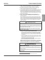
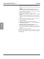
DANGER
HAZARD OF ELECTRIC SHOCK, EXPLOSION, OR ARC FLASH
• Apply appropriate personal protective equipment (PPE) and follow safe
electrical work practices. See NFPA 70E.
• This equipment must only be installed and serviced by qualified
electrical personnel.
• Turn off all power supplying this equipment before working on or inside
equipment.
• Always use a properly rated voltage sensing device to confirm that
power is off.
• Replace all devices, doors, and covers before turning on power to this
equipment.
Failure to follow these instructions will result in death or serious
injury.
WARNING
LOSS OF CONTROL
• The designer of any control scheme must consider the potential failure
modes of control paths and, for certain critical control functions, provide
a means to achieve a safe state during and after a path failure.
Examples of critical control functions are emergency stop and
overtravel stop.
• Separate or redundant control paths must be provided for critical control
functions.
• System control paths may include communication links. Consideration
must be given to the implications of anticipated transmission delays or
failures of the link1.
• Each implementation of an Enclosed 22 controller must be individually
and thoroughly tested for proper operation before being placed into
service.
1For additional information, refer to NEMA ICS 1.1 (latest edition), “Safety Guidelines for the
Application, Installation, and Maintenance of Solid State Control.”
Failure to follow these instructions can result in death, serious
injury, or equipment damage.
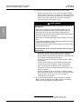
CAUTION
INCOMPATIBLE LINE VOLTAGE
Before turning on and configuring the controller, ensure that the line voltage
is compatible with the line voltage range specified on the controller
nameplate.
The controller can be damaged if the line voltage is not compatible.
Failure to follow these instructions can result in injury or equipment
damage.

Enclosed Altistart™ 22 Motor Controller 30072-453-26
Section 1—Introduction and Technical Characteristics Rev. 03, 12/2012
© 2012 Schneider Electric All Rights Reserved10-EN
ENGLISH
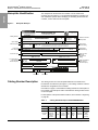
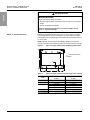
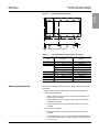
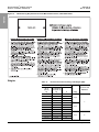
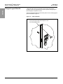
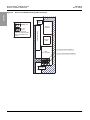
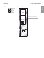
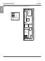
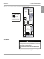
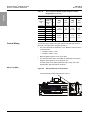
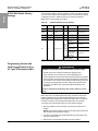
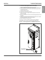
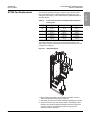
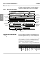
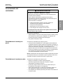
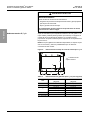
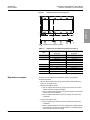
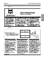
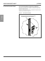
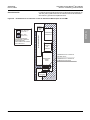
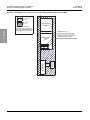
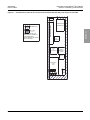
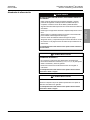
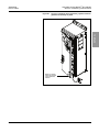
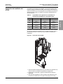
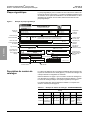
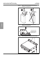
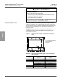
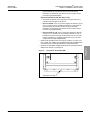
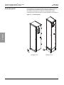
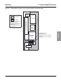
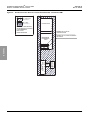
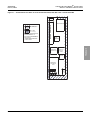
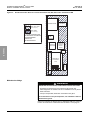
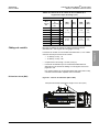
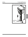
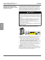
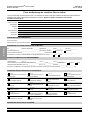
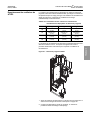
Nameplate Identification The nameplate for the Enclosed 22 controller is on the inside of the
enclosure door. See Figure 1. The nameplate identifies the controller type
and modification options. When identifying or describing the Enclosed 22
controller, use the data from this nameplate.
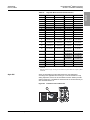
Catalog Number Description The catalog number is on the nameplate attached to the inside of the
Enclosed 22 controller door (see Figure 1). The catalog number is coded to
describe the configuration of the controller.
Use Table 2 on page 11 to translate the catalog number into a description of
the controller. The example in Table 1 translates the catalog number shown
on the nameplate.
For descriptions of the options listed in Table 2, refer to Section 4 beginning
on page 85.
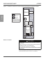
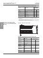
Figure 1: Nameplate Example
LISTED A159
PMET TNEIBMASEIRES
R
EB
MUN GO
LA
TAC
ETN
EIBM
A PMETSEI
RES
OGOL
A
TA
C
ED
O
REM
U
N
E
T
NA
IB
MA
P
M
ETSEI
RES
E
UGOL
A
TA
C
E
D
O
RE
M
U
N
VOLTS Hz
MAX AMPS SHORT CIRCUIT CURRENT RATING (SCCR), RMS, SYMMETRICAL
M
C
R SOCIRTE
MI
S )RC
C
S(
O
TI
UCR
I
CO
TR
OC
ED LA
N
I
MO
N
E
T
N
EI
R
ROCXAM
A
SEU
QI
RT
E
MY
S
,SM
R
)R
CCS
( T
IU
C
RIC-
T
RUO
C
E
D
LANIM
O
N TNARUO
CX
AM
.A
FUSE CLASS
/ CLASE DE FUSIBLE / CLASSE DE FUSIBLE
FUSE AMPERAGE
/ AMPERAJE DE FUSIBLE / AMPERAGE DE FUSIBLE
ENCLOSURE
/ GABINETE/ ARMOIRE
WIRE TYPE AND TEMP/
/ TIPO Y TEMP DE CONDUCTOR / TYPE ET TEMP DE FIL
TYPE
/ TIPO / TYPE
POWER WIRING /
ALAMBRADO DE ALIMENTACION
/
CABLAGE D'ALIMENTACION
AWG TORQUE
/ TORQUE / COUPLE DE SERRAGE
AWG TORQUE
/ TORQUE / COUPLE DE SERRAGE
REFERENCE MANUALS
/ MANUAL DE REFERENCIA / MANUEL DE REFERENCE
DWG
BBV51330 30072-453-26
FO # /
NUMERO DE PEDIDO DE FABRICA / NUMERO DE COMMANDE DE L'USINE
80463-012-01 Rev 0
10 / 7.5
60
ENCLOSED 22
Combination Motor Controller
-
PHASE
/ FASE/ PHASE
3
HP / KW
-
#12 - 4
Cu 75°C
LINE
/ LINEA / LIGNE
LOAD
/ CARGA / CHARGE
12K
#14 - 10
14
C04A
(+ 10 %/-15%)
460
100
KA
0610
50 lb-in
#8 - 3/0 120 lb-in
009
ASSY IN MX
863922UDG4BA06A07
26 lb-in
Short-Circuit
Current Rating
Horsepower/
Kilowatt Rating
Load Terminations
(wire size and
terminal torques)
Catalog Number
Input Voltage
Fuse Class
Line Terminations
(wire size and
terminal torques)
Plant Code
Rated Ampacity
Fuse Ampacity
Enclosure Type
Date Code
Wire Type and
Minimum
Temperature
Rating
Maximum Ambient
Temperature
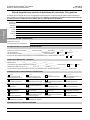
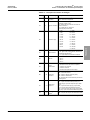
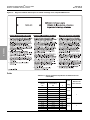
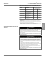
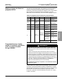
Table 1: Catalog Number Example: 863922UDG4BA06A07
Field
—12345 6 7
8639 22U D G 4 B A06 A07
Controller
Class
PowerPact™
Thermal-
Magnetic
Circuit
Breaker
10 hp
UL Type 1
General
Purpose
460
Vac
Basic
Shunt
Trip
Start-Stop
Pushbutton
Run Light
(Red),
Off Light
(Green)

30072-453-26 Enclosed Altistart™ 22 Motor Controller
Rev. 03, 12/2012 Section 1—Introduction and Technical Characteristics
© 2012 Schneider Electric All Rights Reserved 11-EN
ENGLISH
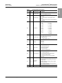
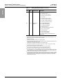
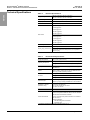
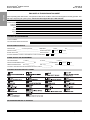
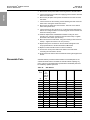
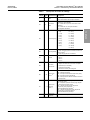
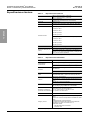
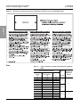
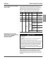
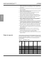
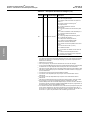
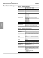
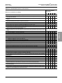
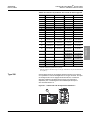
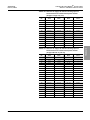
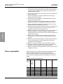
Table 2: Catalog Number Description
Field Digit Characteristic Description
—— Controller Class 8638 = Fused Disconnect1
8639 = Circuit Breaker Disconnect
01 1–3 Controller Style
22F = Altistart 22 with Class J fuse clips and molded
case switch1
22T = Altistart 22 with PowerPact Motor Circuit
Protector
22U = Altistart 22 with PowerPact Thermal-Magnetic
Circuit Breaker
02 4 Horsepower
A = 3 hp L = 60 hp
B = 5 hp M = 75 hp
C = 7.5 hp N = 100 hp
D = 10 hp P = 125 hp
E = 15 hp Q = 150 hp
F = 20 hp R = 200 hp
G = 25 hp S = 250 hp
H = 30 hp T = 300 hp
J = 40 hp U = 350 hp
K = 50 hp W = 400 hp
X = 500 hp
03 5 Enclosure Type
G = UL Type 1 General Purpose
A = UL Type 12/12K Industrial Use,
Dust-Tight/Drip-Tight2
H = UL Type 3R Outdoor Use
04 6 Voltage
2 = 208 Vac
3 = 230 Vac
4 = 460 Vac
5 = 575 Vac
05 7 Power Circuit
B = Basic Shunt Trip
S = Full-Featured Shunt Trip
N = Non-reversing Isolation
R = Reversing Isolation
Y = Integral Full-Voltage Bypass
06 8–10 Control Options 3,4
A06 = Start-Stop Pushbuttons
B06 = Forward-Off-Reverse5
C06 = Hand-Off-Auto (HOA) Selector Switch
D06 = Stop-Run Selector Switch
E06 = Hand-Auto Selector Switch / Start-Stop
Pushbuttons
07 11–13 Pilot Device
Options 3,4
A07 = Run Light (Red), Off Light (Green)
B07 = Push-to-Test Run Light (Red), Push-to-Test
Off Light (Green)
C07 = Run Light (Red), Off Light (Green), Tripped
Light/Reset (Yellow)6
D07 = PTT Run Light (Red), PTT Off Light (Green),
Tripped Light/Reset (Yellow)6
08 14–16 Metering Options 3B08 = Elapsed Run Time Meter
Continued on next page

Enclosed Altistart™ 22 Motor Controller 30072-453-26
Section 1—Introduction and Technical Characteristics Rev. 03, 12/2012
© 2012 Schneider Electric All Rights Reserved12-EN
ENGLISH
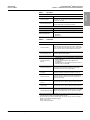
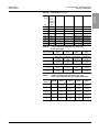
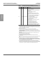
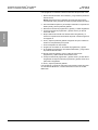
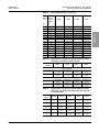
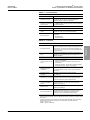
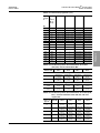
09 17–19 Miscellaneous
Options 3
A10 = Floor Mounting Kit7
B10 = Additional 150 VA1
C10 = Power-Up On Delay Relay1,10
D10 = Emergency Stop Pushbutton1
E10 = cUL Label8
F10 = Auxiliary Run Mode Contacts
G10 = Auxiliary FV Bypass Contacts1,9
H10 = Auxiliary Auto Mode Contacts10,11
J10 = Auxiliary Trip Indication Contacts
L10 = ID Engraved Nameplate1
M10 = 10 Spare Terminal Blocks1
P10 = Permanent Wire Markers1
R10 = MOV/Surge Arrestor1
U10 = Omit Door-Mounted Keypad Display12
X10 = 50 °C (122 °C) Operation
Y10 = Seismic Qualified
Z10 = Service Entrance Rating8
610 = High Interrupting Rating13
910 = American Recovery and Reinvestment Act
(ARRA) Option
1This option is not selectable with power circuit option B05.
2Wall-mounted enclosures include knockouts for conduit connection. Refer to Figures 17–21
beginning on page 40 for knockout location and details.
3Select only one option.
4To omit, do not include a selection in the catalog number.
5Control circuit B06 is required when reversing isolation power circuit (R05) is selected and is not
available with other power circuit options.
6This option is not valid with shunt trip power circuits (B05 or S05).
7This option is available only for enclosure size D. Refer to Table 12 on page 35 for ratings.
8Options E10 and Z10 cannot be ordered together.
9The contacts are available only when power circuit option Y05 is selected.
10 The contacts are not available when power circuit option R05 is selected.
11 This option is valid only with the following control options: C06, D06, or E06.
12 If you select option U10, you must separately order the remote keypad (VW3G22101) and cable
(VW3A1104R30) to commission the soft starter. Refer to the ATS22 User Manual, BBV51330,
for serial communication programming and control capabilities.
13 Enclosed ATS22 controllers sizes E and G with circuit breaker disconnection (22U) are provided
as standard with short circuit ratings of 65 kA @ 460 V and 25 kA @ 575 V. Selection of option
610 increases the rating to 100 kA @ 460 V or 50 kA @ 575 V. The option is not valid with
controller styles 22T or 22F.
Table 2: Catalog Number Description (continued)
Field Digit Characteristic Description

30072-453-26 Enclosed Altistart™ 22 Motor Controller
Rev. 03, 12/2012 Section 1—Introduction and Technical Characteristics
© 2012 Schneider Electric All Rights Reserved 13-EN
ENGLISH
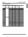
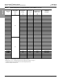
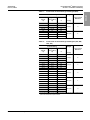
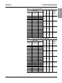
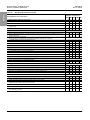
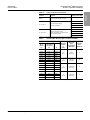
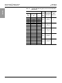
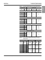
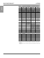
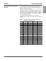
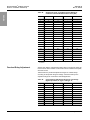
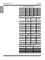
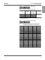
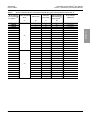
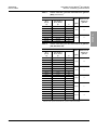
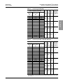
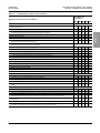
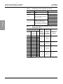
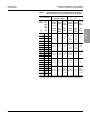
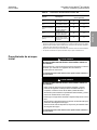
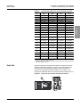
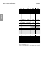
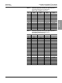
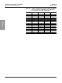
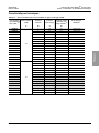
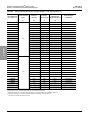
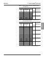
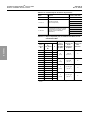
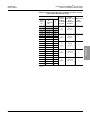
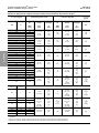
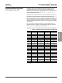
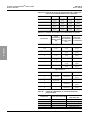
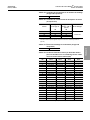
Technical Characteristics
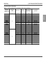
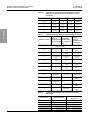
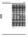
Table 3: Standard Duty Ratings, UL Type 1 and Type 12/12K
Enclosed 22
Catalog No.
1,2,3
Input Voltage
60 Hz
Horsepower
Rating
Full Load
Current
Maximum Total
Dissipated Power at
Rated Load 4,5
Altistart 22
Catalog No.
Vac hp A W
22◆A●2✖
208
3 10.6 65.7 ATS22D17S6U
22◆B●2✖5 16.7 71.8 ATS22D32S6U
22◆C●2✖7.5 24.2 75.0 ATS22D32S6U
22◆D●2✖10 30.8 81.8 ATS22D47S6U
22◆E●2✖15 46.2 95.4 ATS22D62S6U
22◆F●2✖20 59.4 106.7 ATS22D75S6U
22◆G●2✖25 74.8 112.0 ATS22D88S6U
22◆H●2✖30 88 149.0 ATS22C11S6U
22◆J●2✖40 114 182.8 ATS22C14S6U
22◆K●2✖50 143 221.3 ATS22C17S6U
22◆L●2✖60 169 252.6 ATS22C21S6U
22◆M●2✖75 211 307.1 ATS22C25S6U
22◆N●2✖100 273 418.3 ATS22C32S6U
22◆P●2✖125 343 533.0 ATS22C41S6U
22◆Q●2✖150 395 563.0 ATS22C48S6U
22◆B●3✖
230
5 15.2 66.5 ATS22D17S6U
22◆C●3✖7.5 22 74.2 ATS22D32S6U
22◆D●3✖10 28 76.5 ATS22D32S6U
22◆E●3✖15 42 94.0 ATS22D47S6U
22◆F●3✖20 54 101.4 ATS22D62S6U
22◆G●3✖25 68 112.8 ATS22D75S6U
22◆H●3✖30 80 115.6 ATS22D88S6U
22◆J●3✖40 104 163.7 ATS22C11S6U
22◆K●3✖50 130 199.9 ATS22C14S6U
22◆L●3✖60 154 232.9 ATS22C17S6U
22◆M●3✖75 192 273.1 ATS22C21S6U
22◆N●3✖100 248 354.4 ATS22C25S6U
22◆P●3✖125 312 481.6 ATS22C32S6U
22◆Q●3✖150 360 562.3 ATS22C41S6U
22◆R●3✖200 480 691.3 ATS22C59S6U
Continued on next page

Enclosed Altistart™ 22 Motor Controller 30072-453-26
Section 1—Introduction and Technical Characteristics Rev. 03, 12/2012
© 2012 Schneider Electric All Rights Reserved14-EN
ENGLISH
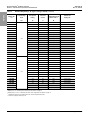
22◆D●4✖
460
10 14 81.2 ATS22D17S6U
22◆E●4✖15 21 88.5 ATS22D32S6U
22◆F●4✖20 27 91.6 ATS22D32S6U
22◆G●4✖25 34 98.7 ATS22D47S6U
22◆H●4✖30 40 107.2 ATS22D47S6U
22◆J●4✖40 52 121.1 ATS22D62S6U
22◆K●4✖50 65 132.0 ATS22D75S6U
22◆L●4✖60 77 134.9 ATS22D88S6U
22◆M●4✖75 96 176.8 ATS22C11S6U
22◆N●4✖100 124 214.6 ATS22C14S6U
22◆P●4✖125 156 256.1 ATS22C17S6U
22◆Q●4✖150 180 263.6 ATS22C21S6U
22◆R●4✖200 240 343.5 ATS22C25S6U
22◆S●4✖250 302 464.5 ATS22C32S6U
22◆T●4✖300 361 564.1 ATS22C41S6U
22◆U●4✖350 414 589.6 ATS22C48S6U
22◆V●4✖400 477 686.6 ATS22C59S6U
22◆E●5✖
575
15 17 82.0 ATS22D17S6U
22◆F●5✖20 22 88.6 ATS22D32S6U
22◆G●5✖25 27 90.7 ATS22D32S6U
22◆H●5✖30 32 96.8 ATS22D47S6U
22◆J●5✖40 41 106.7 ATS22D47S6U
22◆K●5✖50 52 119.3 ATS22D62S6U
22◆L●5✖60 62 127.4 ATS22D75S6U
22◆M●5✖75 77 134.9 ATS22D88S6U
22◆N●5✖100 99 179.4 ATS22C11S6U
22◆P●5✖125 125 215.7 ATS22C14S6U
22◆Q●5✖150 144 243.3 ATS22C17S6U
22◆R●5✖200 192 273.1 ATS22C21S6U
22◆S●5✖250 242 346.2 ATS22C25S6U
22◆T●5✖300 289 443.2 ATS22C32S6U
22◆W●5✖400 382 543.1 ATS22C48S6U
22◆X●5✖500 472 678.8 ATS22C59S6U
1◆ may be F, T or U, describing the controller style. See Table 2 on page 11.
2● may be G or A, describing the enclosure type. See Table 2 on page 11.
3✖may be B, S, N, R, or Y describing the power circuit configuration. See Table 2 on page 11.
4Dissipated power does not include losses of the customer-supplied power fuses.
5For btu/hr, multiply the values by 3.413.
Table 3: Standard Duty Ratings, UL Type 1 and Type 12/12K (continued)
Enclosed 22
Catalog No.
1,2,3
Input Voltage
60 Hz
Horsepower
Rating
Full Load
Current
Maximum Total
Dissipated Power at
Rated Load 4,5
Altistart 22
Catalog No.
Vac hp A W

30072-453-26 Enclosed Altistart™ 22 Motor Controller
Rev. 03, 12/2012 Section 1—Introduction and Technical Characteristics
© 2012 Schneider Electric All Rights Reserved 15-EN
ENGLISH
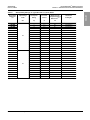
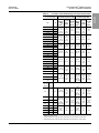
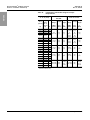
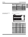
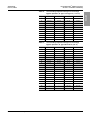
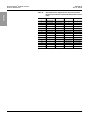
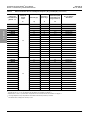
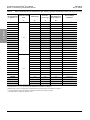
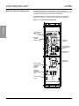
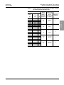
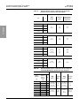
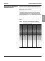
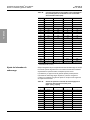
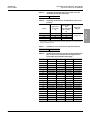
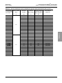
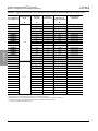
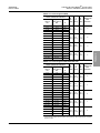
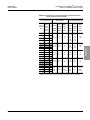
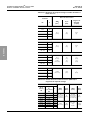
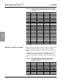
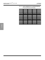
Table 4: Standard Duty Ratings, UL Type 3R and 50 °C (122 °F) Rated
Enclosed 22
Catalog No.
1,2,3
Input Voltage
60 Hz
Horsepower
Rating
Full Load
Current
Maximum Total
Dissipated Power at
Rated Load 4,5
Altistart 22
Catalog No.
Vac hp A W
22◆A●2✖
208
3 10.6 50.4 ATS22D17S6U
22◆B●2✖ 5 16.7 53.3 ATS22D32S6U
22◆C●2✖ 7.5 24.2 60.1 ATS22D47S6U
22◆D●2✖ 10 30.8 70.2 ATS22D47S6U
22◆E●2✖ 15 46.2 74.0 ATS22D75S6U
22◆F●2✖ 20 59.4 83.2 ATS22D88S6U
22◆G●2✖ 25 74.8 118.5 ATS22C11S6U
22◆H●2✖ 30 88 140.3 ATS22C14S6U
22◆J●2✖ 40 114 164.1 ATS22C17S6U
22◆K●2✖50 143 197.8 ATS22C21S6U
22◆L●2✖60 169 236.3 ATS22C25S6U
22◆M●2✖75 211 297.8 ATS22C32S6U
22◆N●2✖100 273 376.1 ATS22C41S6U
22◆P●2✖125 343 434.8 ATS22C48S6U
22◆B●3✖
230
5 15.2 55.1 ATS22D32S6U
22◆C●3✖ 7.5 22 57.5 ATS22D32S6U
22◆D●3✖ 10 28 68.8 ATS22D47S6U
22◆E●3✖ 15 42 69.7 ATS22D62S6U
22◆F●3✖ 20 54 85.3 ATS22D75S6U
22◆G●3✖ 25 68 89.1 ATS22D88S6U
22◆H●3✖ 30 80 127.4 ATS22C11S6U
22◆J●3✖ 40 104 145.5 ATS22C14S6U
22◆K●3✖ 50 130 181.2 ATS22C17S6U
22◆L●3✖ 60 154 213.4 ATS22C21S6U
22◆M●3✖ 75 192 250.7 ATS22C25S6U
22◆N●3✖ 100 248 338.9 ATS22C32S6U
22◆P●3✖ 125 312 438.1 ATS22C41S6U
22◆Q●3✖ 150 360 506.6 ATS22C59S6U
Continued on next page

Enclosed Altistart™ 22 Motor Controller 30072-453-26
Section 1—Introduction and Technical Characteristics Rev. 03, 12/2012
© 2012 Schneider Electric All Rights Reserved16-EN
ENGLISH
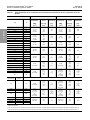
22◆D●4✖
460
10 14 60.4 ATS22D32S6U
22◆E●4✖15 21 63.5 ATS22D32S6U
22◆F●4✖20 27 75.3 ATS22D47S6U
22◆G●4✖25 34 83.3 ATS22D47S6U
22◆H●4✖30 40 95.1 ATS22D62S6U
22◆J●4✖40 52 96.6 ATS22D75S6U
22◆K●4✖50 65 101.9 ATS22D88S6U
22◆L●4✖60 77 139.9 ATS22C11S6U
22◆M●4✖75 96 155.9 ATS22C14S6U
22◆N●4✖100 124 170.4 ATS22C17S6U
22◆P●4✖125 156 208.6 ATS22C21S6U
22◆Q●4✖150 180 251.3 ATS22C25S6U
22◆R●4✖200 240 322.8 ATS22C32S6U
22◆S●4✖250 302 422.9 ATS22C41S6U
22◆T●4✖300 361 471.4 ATS22C48S6U
22◆U●4✖350 414 557.3 ATS22C59S6U
22◆E●5✖
575
15 17 68.3 ATS22D32S6U
22◆F●5✖20 22 70.2 ATS22D32S6U
22◆G●5✖25 27 77.7 ATS22D47S6U
22◆H●5✖30 32 84.9 ATS22D47S6U
22◆J●5✖40 41 89.4 ATS22D62S6U
22◆K●5✖50 52 96.8 ATS22D75S6U
22◆L●5✖60 62 104.5 ATS22D88S6U
22◆M●5✖75 77 135.1 ATS22C11S6U
22◆N●5✖100 99 155.2 ATS22C14S6U
22◆P●5✖125 125 173.4 ATS22C17S6U
22◆Q●5✖150 144 209.5 ATS22C21S6U
22◆R●5✖200 192 240.9 ATS22C25S6U
22◆S●5✖250 242 335.0 ATS22C32S6U
22◆T●5✖300 289 447.7 ATS22C48S6U
22◆W●5✖400 382 541.8 ATS22C59S6U
1◆ may be F, T, or U, describing the controller style. See Table 2 on page 11.
2●may be G, A, or H describing the enclosure type. See Table 2 on page 11.
3✖may be B, S, N, R, or Y describing the power circuit configuration. See Table 2 on page 11.
4Dissipated power does not include losses of the customer-supplied power fuses.
5For btu/hr, multiply the values by 3.413.
Table 4: Standard Duty Ratings, UL Type 3R and 50 °C (122 °F) Rated (continued)
Enclosed 22
Catalog No.
1,2,3
Input Voltage
60 Hz
Horsepower
Rating
Full Load
Current
Maximum Total
Dissipated Power at
Rated Load 4,5
Altistart 22
Catalog No.
Vac hp A W
La page est en cours de chargement...
La page est en cours de chargement...
La page est en cours de chargement...
La page est en cours de chargement...
La page est en cours de chargement...
La page est en cours de chargement...
La page est en cours de chargement...
La page est en cours de chargement...
La page est en cours de chargement...
La page est en cours de chargement...
La page est en cours de chargement...
La page est en cours de chargement...
La page est en cours de chargement...
La page est en cours de chargement...
La page est en cours de chargement...
La page est en cours de chargement...
La page est en cours de chargement...
La page est en cours de chargement...
La page est en cours de chargement...
La page est en cours de chargement...
La page est en cours de chargement...
La page est en cours de chargement...
La page est en cours de chargement...
La page est en cours de chargement...
La page est en cours de chargement...
La page est en cours de chargement...
La page est en cours de chargement...
La page est en cours de chargement...
La page est en cours de chargement...
La page est en cours de chargement...
La page est en cours de chargement...
La page est en cours de chargement...
La page est en cours de chargement...
La page est en cours de chargement...
La page est en cours de chargement...
La page est en cours de chargement...
La page est en cours de chargement...
La page est en cours de chargement...
La page est en cours de chargement...
La page est en cours de chargement...
La page est en cours de chargement...
La page est en cours de chargement...
La page est en cours de chargement...
La page est en cours de chargement...
La page est en cours de chargement...
La page est en cours de chargement...
La page est en cours de chargement...
La page est en cours de chargement...
La page est en cours de chargement...
La page est en cours de chargement...
La page est en cours de chargement...
La page est en cours de chargement...
La page est en cours de chargement...
La page est en cours de chargement...
La page est en cours de chargement...
La page est en cours de chargement...
La page est en cours de chargement...
La page est en cours de chargement...
La page est en cours de chargement...
La page est en cours de chargement...
La page est en cours de chargement...
La page est en cours de chargement...
La page est en cours de chargement...
La page est en cours de chargement...
La page est en cours de chargement...
La page est en cours de chargement...
La page est en cours de chargement...
La page est en cours de chargement...
La page est en cours de chargement...
La page est en cours de chargement...
La page est en cours de chargement...
La page est en cours de chargement...
La page est en cours de chargement...
La page est en cours de chargement...
La page est en cours de chargement...
La page est en cours de chargement...
La page est en cours de chargement...
La page est en cours de chargement...
La page est en cours de chargement...
La page est en cours de chargement...
La page est en cours de chargement...
La page est en cours de chargement...
La page est en cours de chargement...
La page est en cours de chargement...
La page est en cours de chargement...
La page est en cours de chargement...
La page est en cours de chargement...
La page est en cours de chargement...
La page est en cours de chargement...
La page est en cours de chargement...
La page est en cours de chargement...
La page est en cours de chargement...
La page est en cours de chargement...
La page est en cours de chargement...
La page est en cours de chargement...
La page est en cours de chargement...
La page est en cours de chargement...
La page est en cours de chargement...
La page est en cours de chargement...
La page est en cours de chargement...
La page est en cours de chargement...
La page est en cours de chargement...
La page est en cours de chargement...
La page est en cours de chargement...
La page est en cours de chargement...
La page est en cours de chargement...
La page est en cours de chargement...
La page est en cours de chargement...
La page est en cours de chargement...
La page est en cours de chargement...
La page est en cours de chargement...
La page est en cours de chargement...
La page est en cours de chargement...
La page est en cours de chargement...
La page est en cours de chargement...
La page est en cours de chargement...
La page est en cours de chargement...
La page est en cours de chargement...
La page est en cours de chargement...
La page est en cours de chargement...
La page est en cours de chargement...
La page est en cours de chargement...
La page est en cours de chargement...
La page est en cours de chargement...
La page est en cours de chargement...
La page est en cours de chargement...
La page est en cours de chargement...
La page est en cours de chargement...
La page est en cours de chargement...
La page est en cours de chargement...
La page est en cours de chargement...
La page est en cours de chargement...
La page est en cours de chargement...
La page est en cours de chargement...
La page est en cours de chargement...
La page est en cours de chargement...
La page est en cours de chargement...
La page est en cours de chargement...
La page est en cours de chargement...
La page est en cours de chargement...
La page est en cours de chargement...
La page est en cours de chargement...
La page est en cours de chargement...
La page est en cours de chargement...
La page est en cours de chargement...
La page est en cours de chargement...
La page est en cours de chargement...
La page est en cours de chargement...
La page est en cours de chargement...
La page est en cours de chargement...
La page est en cours de chargement...
La page est en cours de chargement...
La page est en cours de chargement...
La page est en cours de chargement...
La page est en cours de chargement...
La page est en cours de chargement...
La page est en cours de chargement...
La page est en cours de chargement...
La page est en cours de chargement...
La page est en cours de chargement...
La page est en cours de chargement...
La page est en cours de chargement...
La page est en cours de chargement...
La page est en cours de chargement...
La page est en cours de chargement...
La page est en cours de chargement...
La page est en cours de chargement...
La page est en cours de chargement...
La page est en cours de chargement...
La page est en cours de chargement...
La page est en cours de chargement...
La page est en cours de chargement...
La page est en cours de chargement...
La page est en cours de chargement...
La page est en cours de chargement...
La page est en cours de chargement...
La page est en cours de chargement...
La page est en cours de chargement...
La page est en cours de chargement...
La page est en cours de chargement...
La page est en cours de chargement...
La page est en cours de chargement...
La page est en cours de chargement...
La page est en cours de chargement...
La page est en cours de chargement...
La page est en cours de chargement...
La page est en cours de chargement...
La page est en cours de chargement...
La page est en cours de chargement...
La page est en cours de chargement...
La page est en cours de chargement...
La page est en cours de chargement...
La page est en cours de chargement...
La page est en cours de chargement...
La page est en cours de chargement...
La page est en cours de chargement...
La page est en cours de chargement...
La page est en cours de chargement...
La page est en cours de chargement...
La page est en cours de chargement...
La page est en cours de chargement...
La page est en cours de chargement...
La page est en cours de chargement...
La page est en cours de chargement...
La page est en cours de chargement...
La page est en cours de chargement...
La page est en cours de chargement...
La page est en cours de chargement...
La page est en cours de chargement...
La page est en cours de chargement...
La page est en cours de chargement...
La page est en cours de chargement...
La page est en cours de chargement...
La page est en cours de chargement...
La page est en cours de chargement...
La page est en cours de chargement...
La page est en cours de chargement...
La page est en cours de chargement...
La page est en cours de chargement...
La page est en cours de chargement...
La page est en cours de chargement...
La page est en cours de chargement...
La page est en cours de chargement...
La page est en cours de chargement...
La page est en cours de chargement...
La page est en cours de chargement...
La page est en cours de chargement...
La page est en cours de chargement...
La page est en cours de chargement...
La page est en cours de chargement...
La page est en cours de chargement...
La page est en cours de chargement...
La page est en cours de chargement...
La page est en cours de chargement...
La page est en cours de chargement...
La page est en cours de chargement...
La page est en cours de chargement...
La page est en cours de chargement...
La page est en cours de chargement...
La page est en cours de chargement...
La page est en cours de chargement...
La page est en cours de chargement...
La page est en cours de chargement...
La page est en cours de chargement...
La page est en cours de chargement...
La page est en cours de chargement...
La page est en cours de chargement...
La page est en cours de chargement...
La page est en cours de chargement...
La page est en cours de chargement...
La page est en cours de chargement...
La page est en cours de chargement...
La page est en cours de chargement...
La page est en cours de chargement...
La page est en cours de chargement...
La page est en cours de chargement...
La page est en cours de chargement...
La page est en cours de chargement...
La page est en cours de chargement...
La page est en cours de chargement...
La page est en cours de chargement...
La page est en cours de chargement...
La page est en cours de chargement...
La page est en cours de chargement...
La page est en cours de chargement...
La page est en cours de chargement...
La page est en cours de chargement...
La page est en cours de chargement...
La page est en cours de chargement...
La page est en cours de chargement...
La page est en cours de chargement...
La page est en cours de chargement...
La page est en cours de chargement...
La page est en cours de chargement...
La page est en cours de chargement...
La page est en cours de chargement...
La page est en cours de chargement...
La page est en cours de chargement...
La page est en cours de chargement...
La page est en cours de chargement...
La page est en cours de chargement...
La page est en cours de chargement...
La page est en cours de chargement...
La page est en cours de chargement...
La page est en cours de chargement...
La page est en cours de chargement...
La page est en cours de chargement...
La page est en cours de chargement...
La page est en cours de chargement...
La page est en cours de chargement...
La page est en cours de chargement...
La page est en cours de chargement...
La page est en cours de chargement...
La page est en cours de chargement...
La page est en cours de chargement...
La page est en cours de chargement...
La page est en cours de chargement...
La page est en cours de chargement...
La page est en cours de chargement...
La page est en cours de chargement...
La page est en cours de chargement...
La page est en cours de chargement...
La page est en cours de chargement...
La page est en cours de chargement...
La page est en cours de chargement...
La page est en cours de chargement...
La page est en cours de chargement...
La page est en cours de chargement...
La page est en cours de chargement...
La page est en cours de chargement...
La page est en cours de chargement...
La page est en cours de chargement...
La page est en cours de chargement...
La page est en cours de chargement...
La page est en cours de chargement...
La page est en cours de chargement...
La page est en cours de chargement...
La page est en cours de chargement...
La page est en cours de chargement...
La page est en cours de chargement...
La page est en cours de chargement...
La page est en cours de chargement...
La page est en cours de chargement...
La page est en cours de chargement...
La page est en cours de chargement...
La page est en cours de chargement...
La page est en cours de chargement...
La page est en cours de chargement...
La page est en cours de chargement...
La page est en cours de chargement...
La page est en cours de chargement...
La page est en cours de chargement...
La page est en cours de chargement...
-
 1
1
-
 2
2
-
 3
3
-
 4
4
-
 5
5
-
 6
6
-
 7
7
-
 8
8
-
 9
9
-
 10
10
-
 11
11
-
 12
12
-
 13
13
-
 14
14
-
 15
15
-
 16
16
-
 17
17
-
 18
18
-
 19
19
-
 20
20
-
 21
21
-
 22
22
-
 23
23
-
 24
24
-
 25
25
-
 26
26
-
 27
27
-
 28
28
-
 29
29
-
 30
30
-
 31
31
-
 32
32
-
 33
33
-
 34
34
-
 35
35
-
 36
36
-
 37
37
-
 38
38
-
 39
39
-
 40
40
-
 41
41
-
 42
42
-
 43
43
-
 44
44
-
 45
45
-
 46
46
-
 47
47
-
 48
48
-
 49
49
-
 50
50
-
 51
51
-
 52
52
-
 53
53
-
 54
54
-
 55
55
-
 56
56
-
 57
57
-
 58
58
-
 59
59
-
 60
60
-
 61
61
-
 62
62
-
 63
63
-
 64
64
-
 65
65
-
 66
66
-
 67
67
-
 68
68
-
 69
69
-
 70
70
-
 71
71
-
 72
72
-
 73
73
-
 74
74
-
 75
75
-
 76
76
-
 77
77
-
 78
78
-
 79
79
-
 80
80
-
 81
81
-
 82
82
-
 83
83
-
 84
84
-
 85
85
-
 86
86
-
 87
87
-
 88
88
-
 89
89
-
 90
90
-
 91
91
-
 92
92
-
 93
93
-
 94
94
-
 95
95
-
 96
96
-
 97
97
-
 98
98
-
 99
99
-
 100
100
-
 101
101
-
 102
102
-
 103
103
-
 104
104
-
 105
105
-
 106
106
-
 107
107
-
 108
108
-
 109
109
-
 110
110
-
 111
111
-
 112
112
-
 113
113
-
 114
114
-
 115
115
-
 116
116
-
 117
117
-
 118
118
-
 119
119
-
 120
120
-
 121
121
-
 122
122
-
 123
123
-
 124
124
-
 125
125
-
 126
126
-
 127
127
-
 128
128
-
 129
129
-
 130
130
-
 131
131
-
 132
132
-
 133
133
-
 134
134
-
 135
135
-
 136
136
-
 137
137
-
 138
138
-
 139
139
-
 140
140
-
 141
141
-
 142
142
-
 143
143
-
 144
144
-
 145
145
-
 146
146
-
 147
147
-
 148
148
-
 149
149
-
 150
150
-
 151
151
-
 152
152
-
 153
153
-
 154
154
-
 155
155
-
 156
156
-
 157
157
-
 158
158
-
 159
159
-
 160
160
-
 161
161
-
 162
162
-
 163
163
-
 164
164
-
 165
165
-
 166
166
-
 167
167
-
 168
168
-
 169
169
-
 170
170
-
 171
171
-
 172
172
-
 173
173
-
 174
174
-
 175
175
-
 176
176
-
 177
177
-
 178
178
-
 179
179
-
 180
180
-
 181
181
-
 182
182
-
 183
183
-
 184
184
-
 185
185
-
 186
186
-
 187
187
-
 188
188
-
 189
189
-
 190
190
-
 191
191
-
 192
192
-
 193
193
-
 194
194
-
 195
195
-
 196
196
-
 197
197
-
 198
198
-
 199
199
-
 200
200
-
 201
201
-
 202
202
-
 203
203
-
 204
204
-
 205
205
-
 206
206
-
 207
207
-
 208
208
-
 209
209
-
 210
210
-
 211
211
-
 212
212
-
 213
213
-
 214
214
-
 215
215
-
 216
216
-
 217
217
-
 218
218
-
 219
219
-
 220
220
-
 221
221
-
 222
222
-
 223
223
-
 224
224
-
 225
225
-
 226
226
-
 227
227
-
 228
228
-
 229
229
-
 230
230
-
 231
231
-
 232
232
-
 233
233
-
 234
234
-
 235
235
-
 236
236
-
 237
237
-
 238
238
-
 239
239
-
 240
240
-
 241
241
-
 242
242
-
 243
243
-
 244
244
-
 245
245
-
 246
246
-
 247
247
-
 248
248
-
 249
249
-
 250
250
-
 251
251
-
 252
252
-
 253
253
-
 254
254
-
 255
255
-
 256
256
-
 257
257
-
 258
258
-
 259
259
-
 260
260
-
 261
261
-
 262
262
-
 263
263
-
 264
264
-
 265
265
-
 266
266
-
 267
267
-
 268
268
-
 269
269
-
 270
270
-
 271
271
-
 272
272
-
 273
273
-
 274
274
-
 275
275
-
 276
276
-
 277
277
-
 278
278
-
 279
279
-
 280
280
-
 281
281
-
 282
282
-
 283
283
-
 284
284
-
 285
285
-
 286
286
-
 287
287
-
 288
288
-
 289
289
-
 290
290
-
 291
291
-
 292
292
-
 293
293
-
 294
294
-
 295
295
-
 296
296
-
 297
297
-
 298
298
-
 299
299
-
 300
300
-
 301
301
-
 302
302
-
 303
303
-
 304
304
-
 305
305
-
 306
306
-
 307
307
-
 308
308
-
 309
309
-
 310
310
-
 311
311
-
 312
312
-
 313
313
-
 314
314
-
 315
315
-
 316
316
-
 317
317
-
 318
318
-
 319
319
-
 320
320
-
 321
321
-
 322
322
-
 323
323
-
 324
324
-
 325
325
-
 326
326
-
 327
327
-
 328
328
-
 329
329
-
 330
330
-
 331
331
-
 332
332
-
 333
333
-
 334
334
-
 335
335
-
 336
336
-
 337
337
-
 338
338
-
 339
339
-
 340
340
-
 341
341
-
 342
342
-
 343
343
-
 344
344
-
 345
345
-
 346
346
-
 347
347
-
 348
348
-
 349
349
-
 350
350
-
 351
351
-
 352
352
-
 353
353


Schneider Electric Enclosed Altistart 22 Solid State Reduced Voltage Combination Motor Controller Instruction Sheet
- Taper
- Instruction Sheet
dans d''autres langues
Documents connexes
-
Schneider Electric TeSys GS Instruction Sheet
-
-
-
Schneider Electric QO24L60NRNM Mode d'emploi
-
-
-
-
-
Schneider Electric Terminal Cover and Lug Shield Kits Instruction Sheet
-
Autres documents
-
ROOMS TO GO 83600049 Assembly Instructions
-
Square D 9422CMP50 Manuel utilisateur
-
Franklin Electric SSP1 Le manuel du propriétaire
-
Hubbell Wiring Device-Kellems PD1330 Guide d'installation
-
-
Schneider PowerPact Manuel utilisateur
-
-
 TELEMECANIQUE ALTISART 3 Le manuel du propriétaire
-
Pass and Seymour AX60 Mode d'emploi
-
