Greenheck 474680 Ceiling Exhaust and Inline Fans Mode d'emploi
- Taper
- Mode d'emploi

®
Ceiling Exhaust and Inline Fans 1
®
Document 474680
Model SP and CSP
Ceiling Exhaust and Inline Fans
Installation, Operation and Maintenance Manual
Please read and save these instructions for future reference. Read carefully before attempting to assemble, install,
operate or maintain the product described. Protect yourself and others by observing all safety information. Failure
to comply with these instructions will result in voiding of the product warranty and may result in personal injury
and/or property damage.
Direct Drive
Ceiling Exhaust Fan
Designed for clean air applications where
low sound levels are required. Many
options and accessories are available
such as lights, motion detectors, ceiling
radiation dampers and speed controls.
Direct Drive
Inline Exhaust Fan
Designed for clean air
applications where low
sound levels are required.
WARNING!
To reduce the risk of fire, electric shock, or injury to persons,
observe the following:
• Suitable for use with solid state speed controls.
• Use this unit only in the manner intended by the manufacturer. If
you have questions, contact the manufacturer.
• Before servicing or cleaning unit, switch power off at service panel
and lock service disconnecting means to prevent power from
being switched on accidentally. When the service disconnecting
means cannot be locked, securely fasten a prominent warning
device, such as a tag, to the service panel.
• Installation work and electrical wiring must be done by qualified
person(s) in accordance with all applicable codes and standards,
including fire-rated construction.
• Sufficient air is needed for proper combustion and exhausting
of gases through the flue (chimney) of fuel burning equipment
to prevent back drafting. Follow the heating equipment
manufacturer’s guideline and safety standards such as those
published by the National Fire Protection Association (NFPA),
and the American Society for Heating, Refrigeration and Air
Conditioning Engineers (ASHRAE) and the local code authorities.
• When cutting or drilling into wall or ceiling, do not damage
electrical wiring or other hidden utilities.
• Select models are acceptable for use over a bathtub or shower
when installed in a GFCI protected branch circuit. (Up through
size SP-A390)
• Never place a switch where it can be reached from a tub or
shower.
• Ducted fans must always be vented to the outdoors.
• These fans are not recommended for cooking exhaust
applications. They are designed primarily for low temperature,
clean air applications only. The diagram shows the minimum
distance these fans should be placed in relation to cooking
equipment.
• Fan/Light
combination not to be installed in a
ceiling thermally
insulated to a value greater than R40.
CAUTION!
• For general ventilating use only. Do not use to exhaust
hazardous or explosive materials and vapors.
AVERTISSEMENT!
Pour réduire le risque d’incendie, de choc électrique ou de
blessure corporelle, respecter cd qui suit:
•
Appareil pouvant être utilisé avec un régulateur de vitesse à semi-
conducteurs.
• Utiliser cet appareil exclusivement comme prévu par le fabricant. En
cas de questions, communiquer avec le fabricant à l’adresse ou au
numéro de téléphone figurant dans la garantie.
• Avant tout entretien ou nettoyage de l’appareil, couper l’alimentation
sur le tableau électrique et verrouiller le dispositif de sectionnement
pour empêcher toute mise sous tension accidentelle. Si le dispositif
de sectionnement ne peut pas être verrouillé, attacher un moyen
de mise en garde bien visible, tel qu’un panonceau, au tableau
électrique.
• La pose et le câblage électrique doivent être effectués par des
personnes qualifiées en conformité avec les codes et normes en
vigueur, y compris pour la résistance au feu du bâtiment.
• Une quantité d’air suffisante est nécessaire pour la bonne
combustion et l’extraction des gaz brûlés par le conduit d’évacuation
(cheminée) d’appareils à combustible afin d’éviter le refoulement.
Veiller à suivre les indications du fabricant du matériel de chauffe,
les normes de sécurité telles que celles publiées par la National Fire
Protection Association (NFPA) et l’American Society for Heating,
Refrigeration and Air Conditioning Engineers (ASHRAE) et la
réglementation en vigueur.
• Lors de la découpe ou du perçage de murs ou plafonds, ne pas
endommager les câbles électriques et autres conduites masquées.
• Certains modèles (jusqu’au modèle SP-A390 inclus) sont approuvés
pour une installation au-dessus d’une baignoire ou d’une douche
sous réserve d’être raccordés à un circuit de dérivation protégé par
un DDFT.
• Ne jamais placer d’interrupteur à un emplacement à portée d’une
baignoire ou d’une douche.
• Les caissons d’extraction à gaine doivent toujours être évacués vers
l’extérieur.
• Ces caissons ne sont pas conseillés pour les applications
d’aspiration de vapeurs de cuisson. Ils sont conçus essentiellement
pour l’aspiration d’air propre à basse température. Le schéma
indique la distance minimale de placement de ces caissons par
rapport à l’équipement de cuisson.
• Le combiné ventilateur/luminaire ne devra pas être installé dans un
plafond ayant une isolation thermique d’une valeur supérieure à R40.
ATTENTION!
•
À utiliser pour la ventilation générale uniquement. Ne pas utiliser pour
l’aspiration de matières et vapeurs dangereuses ou explosives.

Ceiling Exhaust and Inline Fans2
®
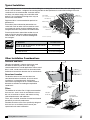
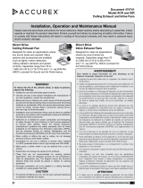
Typical Installation
The ducting from this fan to the outside of the building has a strong effect on the air flow, noise and energy use of
the fan. Use the shortest, straightest duct routing possible for best performance, and avoid installing the fan with
smaller ducts than recommended. Insulation around
the ducts can reduce energy loss and inhibit mold
growth. Fans installed with existing ducts may not
achieve their rated airflow.
Rigid metal duct is recommended for optimal fan
performance.
Ensure duct joints and exterior penetrations are
sealed with caulk or other similar material to create
an air-tight path and to minimize building heat loss
and gain and reduce the potential for condensation.
Place/wrap insulation around duct and/or fan to in
order to minimize possible condensation buildup
within the duct, as well as minimize building heat
loss and gain.
*Pu
rchase separately.
INSUL
ATION*
(Place a
round and over Fan Housing.)
ROOF CAP*
(with built-in damper)
FAN HOUSING
POWER CABLE*
ROUND DUCT*
ROUND
ELBOWS*
Seal gaps
around Housing.
Seal duct joints
with tape.
OR
Keep duct
runs short.
WALL CAP*
(with built-in damper)
Energy Star® Certified
Fan Model/Size
Recommended
Duct Dimensions
SP-A70, SP-A90, SP-A50-90-VG, SP-A90-130-VG,
SP-B70, SP-B80, SP-B90
6 inch round
SP-A110, SP-A125, SP-A190 8 x 6 inch rectangular
SP-A200, SP-A250 8 x 8 inch rectangular
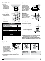
Other Installation Considerations
Ductwork and Noise
Fiberglass ductboard is a better choice than metal
ductwork for reducing fan noise and is highly
recommended for low sound applications. Where metal
duct is used, sound transmission can be reduced with
flexible duct connections between the fan and the duct.
Sound and Location
The location of these fans must be taken into
consideration before installation. In critical sound
installations, insulated ductwork, flexible duct
connections or placing the fan in a remote section of
ductwork are solutions to meeting the required fan
sound levels.
Filters
The addition of an intake filter is highly recommended
for these fans, even in clean air environments excess
dirt can accumulate on wheels and motors causing
reduced performance and imbalance.
Filters, once installed, should be checked and cleaned
periodically to maintain performance.
Washable aluminum mesh filters specifically designed
for these fans are available, please consult your
representative for more information.
Flex Duct
Connections
Fiberglass
Ductboard
Remote
Mounted
Correct Low
Sound Installation
Incorrect
Fan Mounted
Directly Overhead
Fan Converted
to Inline

Ceiling Exhaust and Inline Fans 3
®
B Model
A Model
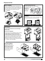
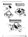
Prepare the Fan
CSP/SP-C Mounting Arrangements
SP/SP-C Ceiling
Mounting
SP/SP-C Wall
Mounting Arrangements
Airflow
Airflow
Airflow
Airflow
Airflow
AirflowAirflow
Airflow
Airflow
Airflow
Access
Panel
Access
Panel
K
n
o
c
k
o
u
t
s
E
l
ec
t
r
i
ca
l
A
cce
ss
P
a
n
e
l
Power Assembly
If power assembly (motor, wheel, and scroll) is not
installed in housing, insert the electrical plug into fan
socket, then slide scroll end of power assembly into
fan housing. Attach by using two sheet metal
screws provided.
Ductwork
Check ductwork to see if the fan’s discharge requires
rotation from horizontal to vertical discharge.
Fan Rotation
To rotate from horizontal to vertical discharge
A Models Only
A50-510, 710, 780 Models
Remove the two screws holding the power assembly
in and pull power assembly out. Rotate power
assembly 180 degrees and put back into fan. Use
the same screws to reattach power assembly to fan
housing. Flip fan over and remove the four screws
holding the discharge duct and damper assembly.
Exchange the assembly with plate mounted on top of
fan, as shown in these illustrations.
Remove Wiring Knockout
Remove either top or side wiring knockout,
depending on wiring
direction, by
bending it back
and forth to
break tabs.
A700, 900-1500 Models
Remove the eight screws
holding the access panel or
collar as shown in picture.
Rotate the fan housing so
the discharge is facing up.
Replace access panel or
collar and screws.

Ceiling Exhaust and Inline Fans4
®
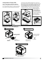
Ceiling Radiation Damper (CRD)
If fan is to be used in a fire resistive membrane
ceiling, a ceiling radiation damper must be used.
If the ceiling radiation damper is already mounted to
the fan from the factory, proceed to Install the Fan.
Attachment Tabs
B Models
To mount the ceiling radiation damper to fan, make sure
grille attachment tabs are facing down. Then place the inlet
part of the fan into the ceiling radiation damper collar, and
use self-tapping sheet metal screws (by others) to screw
through the damper collar and into the fan housing. If the
fan/light combination is being used, make sure ceiling
radiation damper has
an electrical plug in it.
The electrical plug must
be inserted into the fan.
Make sure the electrical
wire will not interfere with
damper operation as
shown in figure below.
Discharge Installation A50-90 Models
A50-510, 710, 780 Models
Wires from lighted grille
Wires to ceiling fan
Do not allow
interference
in this area
A700, 900-1550 Models
Box Slot
Plastic Duct
Adapter Tabs
Insert plastic duct tab into box slots.
Plastic Duct
Adapter (PN
473388
)
Sheet Metal Screw #10x3/8
Phillips Head (PN 415838)
Box
Sheet Metal Screw #10x3/8
Phillips Head (PN 415838)
Box
Plastic Duct
Adapter (PN 473388)
Screw Tabs
Sheet Metal Screw #10x3/8
Phillips Head (PN 415838)
Screw holes
Rotate plastic duct adapter (PN 473388)
until the screw tabs meet the box.
1 2
Install screws provided to secure discharge.
3

Ceiling Exhaust and Inline Fans 5
®
Discharge Installation for Ceiling and Inline Exhaust Models Sizes B50-200
Insert box scroll tab into box scroll slots.
Rotate plastic duct adapter (PN 474433)
until the two mounting tabs fully engage
into the two box mounting slots.
1 2
OPTIONAL
Align the pins on the TR 6x4 adaptor to the duct pin hole on
the 6-inch duct. Push until the adaptor snaps into place.
3
Box Mounting Tabs
Box Mounting Slots
TR 6x4 Pin
TR 6x4
(PN 473324)
6-inch
Plastic Duct
(PN 474433)
Plastic Duct Pin Hole
Updated drawing for #1 supplied to me
by Jesse Welsh on April 5, 2011.
Box Scroll Tabs
Box Scroll Slots

Ceiling Exhaust and Inline Fans6
®
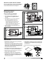
Wire the Fan
115 & 277 Volt
Black wire is “Hot”
White wire is “Neutral”
Green wire is “Ground”
220 - 240 Volt
Black wire is “Hot”
White wire is “Hot”
Green wire is “Neutral/Ground”
Fig. 7a
Fan, No Light Fan and Light
Fig. 7b
Fan, No Light Fan and Light
1. Remove wiring cover.
If fan/accessory
combination is being
used, make sure the
fan plug is connected
to the fan receptacle
and the accessory plug
is connected to the
accessory receptacle,
shown in Fig. 6. Using
proper wire connectors, wire the fan as shown in
Fig.7a. For wiring of light proceed to Fig. 7b.
2. Push all wiring into the unit’s cover and replace
wiring cover.
For Frame Construction:
Position unit between
joists. Position brackets
such that bottom
edge of housing will
be flush with finished
ceiling, and tighten the
adjustable mounting
brackets, shown in
Fig. 3.
For Hanging
Installations:
Use manufacturer’s
optional vibration
isolator kit Part Number
VI Kit. Using the fan’s
standard adjustable
mounting brackets and
10 by 32 threaded rod
(by others), hang unit as
shown in Fig. 4.
Install the Fan
1. For best
performance,
choose a location
with the shortest
possible duct run
and minimum
number of elbows.
Do not mount near
cooking equipment, as
shown in Fig. 1.
2. Attach adjustable
mounting brackets
to fan, but leave the
screws loose until
proper height is
determined, shown
in Fig. 2. Cut hole to
dimensions shown
in table below:
3. Installation of ductwork
is critical to the performance
of the fan, shown in Fig. 5.
Straight ductwork (1) or
ductwork that turns in
the same direction as the
wheel (2) is recommended.
Ductwork turning opposite
the wheel direction (3) will
cause turbulence and back
pressure resulting in poor
performance.
4. Slide ductwork over the fan’s discharge collar and
securely attach it with sheet metal screws.
Make sure the screws do not interfere with damper
operation. Check damper to make sure it opens freely.
Slots in the
brackets
allow fine
adjustment
for flush
fit with
wall/ceiling
opening
Top Mount
Bottom Mount
Brackets can be
used in either
position to adapt to
most mounting
situations
Bottom Mount
Fig. 2
Slots in the
brackets
allow fine
adjustment
for flush
fit with
wall/ceiling
opening
Top Mount
Bottom Mount
Brackets can be
used in either
position to adapt to
most mounting
situations
Bottom Mount
AIRFLOW
1
(GOOD)
3
(POOR)
2
(GOOD)
Fig. 5
45° 45°
Do not install
fan in this area
Ceiling Openings
Ceiling Exhaust Sizes Fan or Fan/Light Fan/CRD
A50, A70, A90, A50-90-VG,
A90-130-VG, A110, A125, A190
10
7
⁄8
x 13
3
⁄8
11
1
⁄8
x 13
7
⁄16
A200, A250, A290, A390 12
1
⁄8
x 14
1
⁄4
12
1
⁄4
x 14
3
⁄8
A700 23
3
⁄4
x 11
3
⁄4
24
1
⁄8
x 12
1
⁄4
A410, A510, A510-VG,
A710, A710-VG, A780
14
3
⁄4
x 18
3
⁄8
14
7
⁄8
x 18
7
⁄16
A900, A1050, A1410, A1550 14
3
⁄4
x 24 14
7
⁄8
x 24
1
⁄8
B50 - 200 14
1
⁄8
x 11
3
⁄4
14
3
⁄8
x 12
1
⁄4
Fig. 3
Fig. 4
NOTE
Model sizes A50-90 are standard with a round duct.
Should any model A110-190 require a round duct,
Model RDC (Round Duct Connector) may be ordered
from manufacturer for field installation.
Fig. 1
Fig. 6
Fan Outlet (top)
Accessory (bottom)
Fan
Light

Ceiling Exhaust and Inline Fans 7
®
Attach the Grille
1. If lighted grille is being used, plug wire from lighted
grille into accessory socket.
If lighted grille and ceiling radiation damper are being
used, plug wire from lighted grille into ceiling radiation
damper socket. Do not plug wire directly into the fan
socket. Make sure the wire does not interfere with the
ceiling radiation damper operation.
2. Attach grille with two screws provided. Make sure not
to over tighten; over tightening will damage grille.
3. Slide attachment screw covers over the attachment
screws, shown in Figure 8 and 9.
4. If lighted grille is being used, install light bulb(s)
into light socket(s). For fluorescent lights, use 27W
GU24 bulbs. For LED lights, use 10W GU24 bulbs.
Manufacturer has replacement 27W GU24 bulbs, call
1-800-355-5354 to order.
5. If lighted grille is being used, snap lens into place, by
pushing on the outside edges of lens, shown in Fig.9.
To remove lens, use a small screw driver and pry on
one side of lens.
6. Turn on power and check fan and light operation.
A50-90-VG and A90-130-VG Fan Models
These fan models utilize an internal switch to set the fan
to run at one of three flows. Please set three position
switch to desired airflow when installing unit.
Whole House Ventilation
Two-Speed Operation
A90 and 110, B50, 80 and 110 Models
1. Install fan per standard instructions.
2. Fan will operate at the certified airflow rate
when wall switch or integrated sensor is
activated.
3. Fan will operate at user set low speed when
wall switch or integrated sensor is off.
a. User defined flow rate can be set by
adjusting the dial pre-installed in the fan.
Airflow is dependent on overall static
pressure in the ductwork. Airflow will need
to be verified with a measuring device.
4. When servicing fan, ensure the circuit is shut
off at the breaker.
A5 0-9 0
50 70 9 0
90 110 130
A9 0-13 0
FAN
FAN
A50-90
50 70 90
90 110 130
A90-130
Fig. 8
Squeeze tabs to
insert/remove lens
Fig. 9
BLACK WIRE
GREEN WIRE
WHITE WIRE
BLACK WIRE
GREEN WIRE
WHITE WIRE
SOLID STATE
SWITCH
RED WIRE
BLACK WIRE
CUSTOMER SUPPLIED
JUNCTION BOX
CUSTOMER
WALL SWITCH
L1 SWITCHED POWER
L2 CONSTANT POWER
RED WIRE
GREEN WIRE
WHITE WIRE
GROUND (EARTH)
NEUTRAL WIRE
GREEN WIRE
LEVER NUT
FAN
SOLID STATE
FAN SPEED CONTROLLER
FAN
Wiring Diagram - Continuous Ventilation
1. L1 Switched Power: Black Wire - Customer connection for switched power to the fan motor for high speed to be landed in lever nut connector.
2. L2 Constant Power: Red Wire - Provides customer connection for constant power to the fan speed controller.
3. L3 Neutral Power: White Wire - Provides customer connection for neutral power to the fan motor.
4. Green Wire - Provides earth ground for customer connection.
JUNCTION BOX
FAN
CUSTOMER
WALL SWITCH
L1 SWITCHED POWER
BLACK WIRE
CUSTOMER SUPPLIED
RED WIRE
SOLID STATE
FAN SPEED CONTROLLER
SWITCH
SOLID STATE
GREEN WIRE
GREEN WIRE
WHITE WIRE
GROUND (EARTH)
NEUTRAL WIRE
L2 CONSTANT POWER
BLACK WIRE
RED WIRE
WHITE WIRE
BLACK WIRE
RED WIRE
WHITE WIRE
OPTIONAL SENSOR:
MOTION
HUMIDITY, or
MOTION & HUMIDITY
BLACK WIRE
GREEN WIRE
WHITE WIRE
BLACK WIRE
GREEN WIRE
WHITE WIRE
RED WIRE
LEVER NUT
LEVER NUTLEVER NUT
FAN
ACC
RED WIRE
Wiring Diagram - Continuous Ventilation with Sensors
1. L1 Switched Power: Black Wire - Customer connection for switched power to the fan motor for high speed to be landed in lever nut connector.
2. L2 Constant Power: Red Wire - Provides customer connection for constant power to the fan speed controller.
3. L3 Neutral Power: White Wire - Provides customer connection for neutral power to the fan motor.
4. Green Wire - Provides earth ground for customer connection.
Wiring Diagram - Continuous Ventilation with Light & Wall Switch
1. L1 Switched Power: Black Wire - Customer connection for switched power to the fan motor for high speed to be landed in lever nut connector.
2. L2 Constant Power: Red Wire - Provides customer connection for constant power to the fan speed controller.
3. L3 Switched Power: Black Wire - Customer connection for switch power to the light to be connected to the black wire from ACC.
4. Neutral Power: White Wire - Provides customer connection for neutral power to the fan motor.
5. Green Wire - Provides earth ground for customer connection.
WITH SENSORS
WITH LIGHT & WALL SWITCH
JUNCTION BOX
FAN
CUSTOMER
WALL SWITCH
L1 SWITCHED POWER
BLACK WIRE
CUSTOMER SUPPLIED
RED WIRE
SOLID STATE
FAN SPEED CONTROLLER
SWITCH
SOLID STATE
GREEN WIRE
GREEN WIRE
WHITE WIRE
GROUND (EARTH)
NEUTRAL WIRE
L2 CONSTANT POWER
BLACK WIRE
WHITE WIRE
BLACK WIRE
WHITE WIRE
LIGHT
BLACK WIRE
GREEN WIRE
WHITE WIRE
BLACK WIRE
GREEN WIRE
WHITE WIRE
RED WIRE
LEVER NUT
LEVER NUT
FAN
ACC
GREEN WIRE
BLACK WIRE
L3 SWITCHED POWER
BLACK WIRE
GREEN WIRE
WHITE WIRE
BLACK WIRE
GREEN WIRE
WHITE WIRE
SOLID STATE
SWITCH
RED WIRE
BLACK WIRE
CUSTOMER SUPPLIED
JUNCTION BOX
CUSTOMER
WALL SWITCH
L1 SWITCHED POWER
L2 CONSTANT POWER
RED WIRE
GREEN WIRE
WHITE WIRE
GROUND (EARTH)
NEUTRAL WIRE
GREEN WIRE
LEVER NUT
FAN
SOLID STATE
FAN SPEED CONTROLLER
FAN
Wiring Diagram - Continuous Ventilation
1. L1 Switched Power: Black Wire - Customer connection for switched power to the fan motor for high speed to be landed in lever nut connector.
2. L2 Constant Power: Red Wire - Provides customer connection for constant power to the fan speed controller.
3. L3 Neutral Power: White Wire - Provides customer connection for neutral power to the fan motor.
4. Green Wire - Provides earth ground for customer connection.
JUNCTION BOX
FAN
CUSTOMER
WALL SWITCH
L1 SWITCHED POWER
BLACK WIRE
CUSTOMER SUPPLIED
RED WIRE
SOLID STATE
FAN SPEED CONTROLLER
SWITCH
SOLID STATE
GREEN WIRE
GREEN WIRE
WHITE WIRE
GROUND (EARTH)
NEUTRAL WIRE
L2 CONSTANT POWER
BLACK WIRE
RED WIRE
WHITE WIRE
BLACK WIRE
RED WIRE
WHITE WIRE
OPTIONAL SENSOR:
MOTION
HUMIDITY, or
MOTION & HUMIDITY
BLACK WIRE
GREEN WIRE
WHITE WIRE
BLACK WIRE
GREEN WIRE
WHITE WIRE
RED WIRE
LEVER NUT
LEVER NUTLEVER NUT
FAN
ACC
RED WIRE
Wiring Diagram - Continuous Ventilation with Sensors
1. L1 Switched Power: Black Wire - Customer connection for switched power to the fan motor for high speed to be landed in lever nut connector.
2. L2 Constant Power: Red Wire - Provides customer connection for constant power to the fan speed controller.
3. L3 Neutral Power: White Wire - Provides customer connection for neutral power to the fan motor.
4. Green Wire - Provides earth ground for customer connection.
Wiring Diagram - Continuous Ventilation with Light & Wall Switch
1. L1 Switched Power: Black Wire - Customer connection for switched power to the fan motor for high speed to be landed in lever nut connector.
2. L2 Constant Power: Red Wire - Provides customer connection for constant power to the fan speed controller.
3. L3 Switched Power: Black Wire - Customer connection for switch power to the light to be connected to the black wire from ACC.
4. Neutral Power: White Wire - Provides customer connection for neutral power to the fan motor.
5. Green Wire - Provides earth ground for customer connection.
WITH SENSORS
WITH LIGHT & WALL SWITCH
JUNCTION BOX
FAN
CUSTOMER
WALL SWITCH
L1 SWITCHED POWER
BLACK WIRE
CUSTOMER SUPPLIED
RED WIRE
SOLID STATE
FAN SPEED CONTROLLER
SWITCH
SOLID STATE
GREEN WIRE
GREEN WIRE
WHITE WIRE
GROUND (EARTH)
NEUTRAL WIRE
L2 CONSTANT POWER
BLACK WIRE
WHITE WIRE
BLACK WIRE
WHITE WIRE
LIGHT
BLACK WIRE
GREEN WIRE
WHITE WIRE
BLACK WIRE
GREEN WIRE
WHITE WIRE
RED WIRE
LEVER NUT
LEVER NUT
FAN
ACC
GREEN WIRE
BLACK WIRE
L3 SWITCHED POWER
Continuous Ventilation
Continuous Ventilation with SensorsContinuous Ventilation with Light & Wall Switch

474680 • SP CSP, Rev. 5, November 2018 Copyright 2018 © Greenheck Fan Corporation8
As a result of our commitment to continuous improvement, Greenheck reserves the right to change specifications
without notice.
Specific Greenheck product warranties are located on greenheck.com within the product area tabs and in the
Library under Warranties.
®
Phone: 715.359.6171 • Fax: 715.355.2399 • Parts: 800.355.5354 • E-mail: [email protected] • Website: www.greenheck.com
Our Commitment
AMCA Publication 410-96, Safety Practices for Users and
Installers of Industrial and Commercial Fans, provides
additional safety information. This publication can be
obtained from AMCA International, Inc. at www.amca.org.
Greenheck’s Centrifugal Ceiling and Cabinet Exhaust Fans
catalog provides additional information describing the
equipment, fan performance, available accessories, and
specification data.
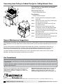
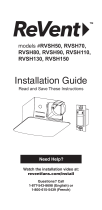
Converting from Ceiling to Cabinet Design for Ceiling Exhaust Fans
Step 1: Remove grille (A) by removing the two grille
screws (B).
Step 2: Remove duct collar cover (C) by removing the
four duct collar screws (D).
Step 3: Discard grille (A), two grille screws (B), and
duct collar cover (C).
Step 4: Remove the six (6) tinnerman clips (E) by
twisting them to one side and pulling straight
out. Discard two of the six tinnerman clips.
Step 5: Insert the remaining four tinnerman clips (E) on
grille opening side.
Step 6: Place blower box cover (F) over tinnerman clips
(E), which were inserted in step 5.
Step 7: Screw the blower box cover (F) into place with
four blower box cover screws (D).
B
A
C
E
D
D
F
E
B
A
C
E
D
D
F
E
All convertible sizes will be shipped with grille and duct
collar cover. Note, this applies only to fans originally
ordered as convertible.
Conversion Kit Parts List
• Qty. of 1 Blower Box Cover
Tools Required
• Phillips Head Screwdriver
General Maintenance Suggestions
Ceiling exhaust fans require very little maintenance, but since small problems over time left unchecked could lead to
loss of performance or early motor failure, we do recommend that the unit be inspected periodically (once or twice a
year).
The fan motor and wheel should be checked for dust and dirt accumulations. Dirt buildup can lead to loss of
performance and motor overheating. Cleaning can be accomplished by brushing off any dust that may have
accumulated. Even filtered units can accumulate build-up and should be checked when cleaning filters.
The motor should be checked for lubrication at this time. Lubricate only those motors which have an oil hole
provided. A few drops of all purpose oil (SAE 20) will be sufficient.
-
 1
1
-
 2
2
-
 3
3
-
 4
4
-
 5
5
-
 6
6
-
 7
7
-
 8
8


Greenheck 474680 Ceiling Exhaust and Inline Fans Mode d'emploi
- Taper
- Mode d'emploi
dans d''autres langues
Documents connexes
-
Greenheck SP-L, Wall/Ceiling Exhaust Fan Manuel utilisateur
-
-
-
-
Autres documents
-
 Accurex XCR-B Ceiling Exhaust Fan Mode d'emploi
-
 ReVent RVSH50 Mode d'emploi
-
Hampton Bay LDS-BF3003 Mode d'emploi
-
Air King ESAP30ADA Guide d'installation
-
-
AirKing ESZ366ADA Manuel utilisateur
-
Air King LE300 Series Manuel utilisateur
-

