Empire Heating Systems Direct-Vent Wall Furnace (DV25/35) Le manuel du propriétaire
- Taper
- Le manuel du propriétaire

Page 1
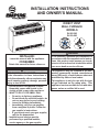
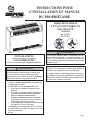
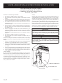
DIRECT VENT
WALL FURNACE
MODELS
DV-25-5SG
DV-35-4SG
This appliance may be installed in an after-
market, permanently located, manufactured
home (USA only), or mobile home, where not
prohibited by state or local codes.
This appliance is only for use with the type
of gas indicated on the rating plate. This
appliance is not convertible for use with other
WARNING
FIRE OR EXPLOSION HAZARD
If the information in these instructions is
result causing property damage, personal
injury or loss of life.
— Do not store or use gasoline or other
vicinity of this or any other appliance.
— WHAT TO DO IF YOU SMELL GAS
not use any phone in your building.
from a neighbor’s phone. Follow the
gas supplier’s instructions.
— Installation and service must be
service agency or the gas supplier.
INSTALLER:
Leave this manual with the appliance.
CONSUMER:
Retain this manual for future reference.
WARNING
If not installed, operated and maintained in
accordance with the manufacturer's instruc-
tions, this product could expose you to sub-
stances in fuel or from fuel combustion which
can cause death or serious illness.
INSTALLATION INSTRUCTIONS
AND OWNER'S MANUAL

37408-5-0919Page 2
TABLE OF CONTENTS
Important Safety Information ..........................................................................................................3
Safety Information for Users of Propane Gas ................................................................................4
Requirements for Massachusetts ...................................................................................................5
Introduction..................................................................................................................................6-7
Specications .................................................................................................................................7
Gas Supply .....................................................................................................................................8
Clearances ..................................................................................................................................10
Installation Instructions ............................................................................................................10-12
Optional Thermostat Location ......................................................................................................13
Lighting Instructions ....................................................................................................................14
Pilot Flame Characteristics ..........................................................................................................15
Main Burner Flame Characteristics .............................................................................................15
Maintenance .................................................................................................................................16
Troubleshooting ............................................................................................................................16
Master Parts Distributor List .........................................................................................................17
How to Order Repair Parts ...........................................................................................................17
Parts List .....................................................................................................................................18
Parts View ....................................................................................................................................19
Optional Blower Installation Instructions ................................................................................20-21
Appliance Service History .......................................................................................................22-23
Warranty .......................................................................................................................................24
SECTION PAGE

37408-5-0919 Page 3
draperies.
of high surface temperatures and should stay away
to avoid burns or clothing ignition.
they are in the same room as the appliance.
placed on or near the appliance.
an appliance must be replaced prior to operating
the appliance.
Installation and repair should be done by a QUALI-
FIED SERVICE PERSON. The appliance should be
inspected before use and at least annually by a
-
ing, bedding materials, etc. It is imperative that
control compartments, burners and circulating air
passageways of the appliance be kept clean.
put anything around the furnace that will
keep the appliance area clear and free from
examine venting system periodically and replace
damaged parts.
make a periodic visual check of pilot and burner.
Clean and replace damaged parts.
closed during operation.
use this heater if any part has been under
-
cian to inspect the heater and to replace any part
of the control system and any gas control which
has been under water.
THIS IS A HEATING APPLIANCE
DO NOT OPERATE THIS APPLIANCE WITHOUT FRONT PANEL INSTALLED.
IMPORTANT SAFETY INFORMATION

37408-5-0919Page 4
SAFETY INFORMATION FOR USERS OF PROPANE GAS
-
sions. In its natural state, propane is odorless and colorless.
You may not know all the following safety precautions which
can protect both you and your family from an accident. Read
them carefully now, then review them point by point with the
members of your household. Someday when there may not
be a minute to lose, everyone's safety will depend on knowing
exactly what to do. If, after reading the following information,
you feel you still need more information, please contact your
gas supplier.
PROPANE GAS WARNING ODOR
If a gas leak happens, you should be able to smell the gas
because of the odorant put in the Propane Gas.
That's your signal to go into immediate action!
• Donotoperateelectricswitches,lightmatches,useyourphone.
Do not do anything that could ignite the gas.
• Geteveryoneoutofthebuilding,vehicle,trailer,orarea.Do
that IMMEDIATELY.
• Closeallgastankorcylindersupplyvalves.
• PropaneGasisheavierthanairandmaysettleinlowareas
such as basements. When you have reason to suspect a gas
leak,keepoutofbasementsandotherlowareas.Stayout
untilreghtersdeclarethemtobesafe.
• Useyourneighbor'sphoneandcallatrainedPropaneGas
servicepersonandtheredepartment.Eventhoughyoumay
notcontinuetosmellgas,donotturnonthegasagain.Donot
re-enterthebuilding,vehicle,trailer,orarea.
• Finally, lettheservicemanandreghterscheckforescaped
gas. Have them air out the area before you return. Properly
trainedPropaneGasservicepeopleshould repairtheleak,
thencheckandrelightthegasapplianceforyou.
NO ODOR DETECTED - ODOR FADE
Some people cannot smell well. Some people cannot smell the
odorofthechemicalputintothegas.Youmustndoutifyoucan
smelltheodorantinpropane.Smokingcandecreaseyourabilityto
smell. Being around an odor for a time can affect your sensitivity or
abilitytodetectthatodor.Sometimesotherodorsintheareamask
the gas odor. People may not smell the gas odor or their minds are
onsomethingelse.Thinkingaboutsmellingagasodorcanmake
it easier to smell.
TheodorantinPropaneGasiscolorless,anditcanfadeundersome
circumstances.Forexample,ifthereisanundergroundleak,the
movementofthegasthroughsoilcanltertheodorant.Odorants
in Propane Gas also are subject to oxidation. This fading can occur
ifthereisrustinsidethestoragetankorinirongaspipes.
The odorant in escaped gas can adsorb or absorb onto or into
walls,masonryandothermaterialsandfabricsinaroom.Thatwill
takesomeoftheodorantoutofthegas,reducingitsodorintensity.
PropaneGasmaystratifyinaclosedarea,andtheodorintensity
couldvaryatdifferentlevels.Sinceitisheavierthanair,theremay
be more odor at lower levels. Always be sensitive to the slightest gas
odor.Ifyoudetectanyodor,treatitasaseriousleak.Immediately
go into action as instructed earlier.
SOME POINTS TO REMEMBER
•
Learn to recognize the odor of Propane Gas. Your local Pro-
pane Gas Dealer can give you a "Scratch and Sniff" pamphlet.
Useittondoutwhatthepropaneodorsmellslike.Ifyou
suspectthatyourPropaneGashasaweakorabnormalodor,
call your Propane Gas Dealer.
• Ifyouarenotqualied,donotlightpilotlights,performservice,
ormakeadjustmentstoappliancesonthePropaneGassystem.
Ifyouarequalied,consciouslythinkabouttheodorofPropane
Gas prior to and while lighting pilot lights or performing service
ormakingadjustments.
• Sometimesa basement or aclosed-up house has a musty
smell that can cover up the Propane Gas odor. Do not try to
lightpilotlights,performservice,ormakeadjustmentsinan
area where the conditions are such that you may not detect
theodoriftherehasbeenaleakofPropaneGas.
• Odorfade,duetooxidationbyrustoradsorptiononwallsof
newcylindersandtanks,ispossible.Therefore,peopleshould
beparticularlyalertandcarefulwhennewtanksorcylinders
areplacedinservice.Odorfadecanoccurinnewtanks,or
reinstalledoldtanks,iftheyarelledandallowedtosettoo
longbeforerelling.Cylindersandtankswhichhavebeenout
of service for a time may develop internal rust which will cause
odorfade.Ifsuchconditionsaresuspectedtoexist,aperiodic
sniff test of the gas is advisable. If you have any question about
thegasodor,callyourPropane Gas dealer. A periodic sniff
test of the Propane Gas is a good safety measure under any
condition.
• If,atanytime,youdonotsmellthePropaneGasodorantand
youthinkyoushould,assumeyouhavealeak.Thentakethe
same immediate action recommended above for the occasion
when you do detect the odorized Propane Gas.
• Ifyouexperienceacomplete"gasout,"(thecontainerisunder
novaporpressure),turnthetankvalveoffimmediately.Ifthe
containervalveislefton,thecontainermaydrawinsomeair
throughopeningssuchaspilotlightorices.Ifthisoccurs,some
newinternalrustingcouldoccur.Ifthevalveisleftopen,then
treatthecontainerasanewtank.Alwaysbesureyourcon-
tainer is under vapor pressure by turning it off at the container
beforeitgoescompletelyemptyorhavingitrelledbeforeitis
completely empty.

37408-5-0919 Page 5
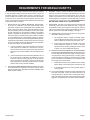
REQUIREMENTS FOR MASSACHUSETTS
For all side wall horizontally vented gas fueled equipment installed
ineverydwelling,buildingorstructureusedinwholeorinpartfor
residential purposes, including those owned or operated by the
Commonwealth and where the side wall exhaust vent termination
islessthanseven(7)feetabovenishedgradeintheareaofthe
venting,includingbutnotlimitedtodecksandporches,thefollowing
requirementsshallbesatised:
1. INSTALLATION OF CARBON MONOXIDE DETECTORS.
At the time of installation of the side wall horizontal vented
gasfueledequipment,theinstallingplumberorgasttershall
observe that a hard wired carbon monoxide detector with an
alarmandbatteryback-upisinstalledontheoorlevelwhere
thegasequipmentistobeinstalled.Inaddition,theinstalling
plumberorgasttershallobservethatabatteryoperatedor
hard wired carbon monoxide detector with an alarm is installed
oneachadditionallevelofthedwelling,buildingorstructure
served by the side wall horizontal vented gas fueled equipment.
It shall be the responsibility of the property owner to secure the
servicesofqualiedlicensedprofessionalsfortheinstallation
of hard wired carbon monoxide detectors
a. In the event that the side wall horizontally vented gas fu-
eledequipmentisinstalledinacrawlspaceoranattic,
the hard wired carbon monoxide detector with alarm and
batteryback-upmaybeinstalledonthenextadjacentoor
level.
b. In the event that the requirements of this subdivision can not
bemetatthetimeofcompletionofinstallation,theowner
shallhaveaperiodofthirty(30)daystocomplywiththe
aboverequirements;provided,however,thatduringsaid
thirty(30)dayperiod,abatteryoperatedcarbonmonoxide
detector with an alarm shall be installed.
2. APPROVED CARBON MONOXIDE DETECTORS. Each carbon
monoxide detector as required in accordance with the above
provisions shall comply with NFPA 720 and be ANSI/UL 2034
listedandIAScertied.
3. SIGNAGE.Ametalorplasticidenticationplateshallbeper-
manently mounted to the exterior of the building at a minimum
heightof eight (8) feetabove grade directly in linewith the
exhaust vent terminal for the horizontally vented gas fueled
heatingapplianceorequipment.Thesignshallread,inprintsize
nolessthanone-half(1/2)inchinsize, “GAS VENT DIRECTLY
4. INSPECTION. The state or local gas inspector of the side wall
horizontally vented gas fueled equipment shall not approve
theinstallationunless,uponinspection,theinspectorobserves
carbon monoxide detectors and signage installed in accordance
withtheprovisionsof248CMR5.08(2)(a)1through4.
(b) EXEMPTIONS:Thefollowingequipmentisexemptfrom
248CMR5.08(2)(a)1through4:
1. The equipment listed in Chapter 10 entitled “Equip-
ment Not Required To Be Vented” in the most current
edition of NFPA 54 as adopted by the Board; and
2. Product Approved side wall horizontally vented gas
fueled equipment installed in a room or structure
separatefromthedwelling,buildingorstructureused
in whole or in part for residential purposes.
(c) MANUFACTURERREQUIREMENTS-GASEQUIPMENT
VENTING SYSTEM PROVIDED. When the manufacturer of
Product Approved side wall horizontally vented gas equip-
ment provides a venting system design or venting system
componentswiththeequipment,theinstructionsprovided
by the manufacturer for installation of the equipment and
theventingsystemshallinclude:
1. Detailed instructions for the installation of the venting
system design or the venting system components; and
2. A complete parts list for the venting system design or
venting system.
(e) AcopyofallinstallationinstructionsforallProductApproved
side wall horizontally vented gas fueled equipment, all
ventinginstructions,allpartslistsforventinginstructions,
and/or all venting design instructions shall remain with the
appliance or equipment at the completion of the installation.

37408-5-0919Page 6
Introduction
AlwaysconsultyourlocalBuildingDepartmentregardingregulations,
codes or ordinances which apply to the installation of a direct vent
wall furnace.
Instructions to Installer
1. Installer must leave instruction manual with owner after
installation.
2. Installermusthaveownerlloutandmailwarrantycardsupplied
with furnace.
3. Installer should show owner how to start and operate furnace
and thermostat.
WARNING
Any change to this furnace or its control can be dangerous.
This is a heating appliance and any panel, door or guard
removed for servicing an appliance must be replaced prior
to operating the appliance.
To Conserve Gas: Turn off pilot when heater is not in use.
General Information
ThisfurnaceisdesigncertiedinaccordancewithAmericanNational
Standard/CSA Standard Z21.86 and CSA 2.32 by the Canadian
StandardAssociation,asaGravityDirectVentWallFurnacetobe
installed on an outside wall according to these instructions.
Anyalterationoftheoriginaldesign,installedotherthanasshown
in these instructions or use with a type of gas not shown on the
ratingplateistheresponsibilityofthepersonandcompanymaking
the change.
Important
AllcorrespondenceshouldrefertocompleteModelNo.,SerialNo.
and type of gas.
Notice:Duringinitialringofthisunit,itspaintwillbakeoutand
smokewilloccur.Topreventtriggeringofsmokealarms,ventilate
the room in which the unit is installed.
Installation in Residential Garages
Gas utilization equipment in residential garages shall be installed
so that all burners and burner ignition devices are located not less
than18"(457mm)abovetheoor.
Suchequipmentshallbelocated,orprotected,soitisnotsubject
to physical damage by a moving vehicle.
Installationandreplacementofgaspiping,gasutilizationequipment
or accessories and repair and servicing of equipment shall be
performedonlybyaqualiedagency.Theterm"qualiedagency"
meansanyindividual,rm,corporationorcompanywhicheitherin
person or through a representative is engaged in and is responsible for
(a)theinstallationorreplacementofgaspipingor(b)theconnection,
installation,repairorservicingofequipment,whoisexperiencedin
suchwork,familiarwithallprecautionsrequiredandhascomplied
with all the requirements of the authority having jurisdiction.
Commonwealth of Massachusetts: The installation must be
madebyalicensedplumberorgastterintheCommonwealth
of Massachusetts.
Theinstallationmustconformwithlocalcodesor,intheabsenceof
localcodes,withthe National Fuel Gas Code ANSI Z223.1/NFPA
54* Natural Gas and Propane Installation Code, CSA B149.1.
*Available from the American National Standards Institute, Inc., 11
West 42nd St., New York, NY 10036.
High Altitudes
For altitudes/elevations above 2,000 feet (610m), input ratings
shouldbereducedattherateof4percentforeach1,000(305m)
feet above sea level. Canadian High Altitudes for locations having
an elevation above mean sea level between 2,000 feet (610m)
and4,500feet(1370m),themanifoldpressureistobedecreased
from4.0"w.c.(.996kPa)to3.2"w.c.(.796kPa)forNaturalGasand
from9.0"w.c.(2.49kPa)to7.0"w.c.(1.992kPa)forPropaneGas.
INTRODUCTION

37408-5-0919 Page 7
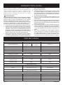
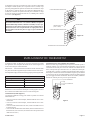
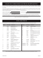
SPECIFICATIONS
INTRODUCTION (CONT'D)
Model DV-25 DV-35
InputBTU/HR(KW/H)
25,000(7.3)
Natural
24,000(7.0)
Propane
35,000(10.3)
Height 28"(711mm) 28"(711mm)
Width 37"(940mm) 37"(940mm)
Depth 111/2"(292mm) 111/2"(292mm)
GasInlet(Pipe) 1/2"(13mm) 1/2"(13mm)
Accessories for the Above Furnaces
BlowerKit DRB-1 DRB-1
Description Model Number
VinylSidingVentKit DV-822 DV-822
VinylSidingVentKit VSK-2 VSK-2
Model Number Description Used On
DV984
VentExtensionKitForPropane
Units(13"-19"Walls)
DV35-4SGLPG
DV983
VentExtensionKitForPropane
Units(13"-19"Walls)
DV35-4SGNAT
Part Number Description Used On
17085 Propane to Natural DV25-5SGLPG
17084 Natural to Propane DV25-5SGNAT
17087 Propane to Natural DV35-4SGLPG
17086 Natural to Propane DV35-4SGNAT
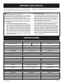
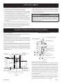
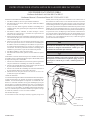
WhenanexistingCategory1heaterisremovedorreplaced,the
original venting system may no longer be sized to properly vent the
attached appliances. Instructions shall also indicate effects of an
improperlysizedventingsystem(formationofcondensate,leakage,
spillage,etc.)andshallspecifythefollowingtestprocedure:
WARNING
CARBON MONOXIDE POISONING HAZARD
Failure to follow the steps outlined below for each appliance
connected to the venting system being placed into operation
could result in carbon monoxide poisoning or death.
The following steps shall be followed for each appliance
connected to the venting system being placed into operation,
while all other appliances connected to the venting system are
not in operation:
1. Seal any unused openings in the venting system.
2.
Z223.1/NFPA 54 or the Natural Gas and Propane Installation
Code, CSA B149.1 and these instructions. Determine that
there is no blockage or restriction, leakage, corrosion and
3. As far as practical, close all building doors and windows
and all doors between the space in which the appliance(s)
connected to the venting system are located and other
spaces of the building.
4.
5. Turn on clothes dryers and any appliance not connected
to the venting system. Turn on any exhaust fans, such as
range hoods and bathroom exhausts, so they are operating
at maximum speed. Do operate a summer exhaust fan.
6. Follow the lighting instructions. Place the appliance
being inspected into operation. Adjust the thermostat so
appliance is operating continuously.
7.
at the draft hood relief opening after 5 minutes of main
8. If improper venting is observed during any of the above
tests, the venting system must be corrected in accordance
with National Fuel Gas Code, ANSI Z223.1/NFPA 54 and/or
Natural Gas and Propane Installation Code, CSA B149.1.
9. After is has been determined that each appliance connected
to the venting system properly vents when tested as outlined
previous conditions of use.

37408-5-0919Page 8
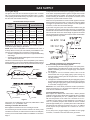
GAS SUPPLY
Locating Gas Supply
Thegaslinecanentertheuniteitherthroughtheoororoutside
wall. The gas line opening should be made at this time. Location
oftheopeningwillbedeterminedbythepositionofoorjoistsand
the valve and union used for servicing.
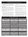
Recommended Gas Pipe Diameter
Pipe
Length
Schedule 40 Pipe
Inside Diameter
Tubing, Type L
Outside Diameter
Natural Propane Natural Propane
0-10 feet
0-3 meters
1/2”
12.7 mm
3/8”
9.5mm
1/2”
12.7 mm
3/8”
9.5 mm
10-40 feet
4-12 meters
1/2”
12.7 mm
1/2”
12.7mm
5/8”
15.9 mm
1/2”
12.7 mm
40-100 feet
13-30 meters
1/2”
12.7 mm
1/2”
12.7mm
3/4”
19 mm
1/2”
12.7 mm
100-150 feet
31-46 meters
3/4”
19 mm
1/2”
12.7 mm
7/8”
22.2 mm
3/4”
19 mm
NOTE:Neveruseplasticpipe.Checktoconrmwhetheryourlocal
codes allow copper tubing or galvanized.
NOTE: Sincesomemunicipalitieshaveadditionallocalcodes,it
is always best to consult your local authority and installation code.
Theuseofthefollowinggasconnectorsisrecommended:
— ANS Z21.24 Appliance Connectors of Corrugated Metal Tubing
and Fittings
— ANS Z21.45 Assembled Flexible Appliance Connectors of Other
Than All-Metal Construction
The above connectors may be used if acceptable by the authority
having jurisdiction. The Commonwealth of Massachusetts requires
thataexibleapplianceconnectorcannotexceedthreefeetinlength.
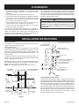
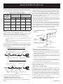
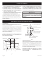
GAS SUPPLY
TEE HANDLE
FLEX TUBING
NPT NIPPLE
FLARE FITTING
FLARE SHUT OFF VALVE
CLOSE NIPPLE
TEE HANDLE
NPT NIPPLE
NPT UNION
SHUT OFF VALVE
NPT GAS SUPPLY
Figure 1
ConsultthecurrentNationalFuelGasCode,ANSIZ223.1CAN/
CGA-B149(.1or.2)installationcode.
Installing a New Main Gas Shut-Off
Each appliance should have its own manual gas shut-off.
A manual main gas shut-off should be located in the vicinity of the
unit.Wherenoneexists,orwhereitssizeorlocationisnotadequate,
contact your local authorized installer for installation or relocation.
Compounds used on threaded joints of gas piping shall be resistant
totheactionofliqueedpetroleumgases.Thegaslinesmustbe
checkedforleaksbytheinstaller.Thisshouldbedonewithasoap
solutionwatchingforbubblesonallexposedconnections,andif
unexposed,apressuretestshouldbemade.
Neveruseanexposedametocheckforleaks.Appliancemustbe
disconnected from piping at inlet of control valve and pipe capped
or plugged for pressure test. Never pressure test with appliance
connected; control valve will sustain damage!
A gas valve and ground joint union should be installed in the gas
line upstream of the gas control to aid in servicing. It is required by
the National Fuel Gas Code that a drip line be installed near the gas
inlet. This should consist of a vertical length of pipe tee connected
into the gas line that is capped on the bottom in which condensation
and foreign particles may collect.
Figure 2
Method of Installing a Tee Fitting Sediment Trap
Pressure Testing of the Gas Supply System
1. Tochecktheinletpressuretothegasvalve,a1/8"(3mm)N.P.T.
pluggedtapping,accessiblefortestgaugeconnection,mustbe
placed immediately upstream of the gas supply connection to
the appliance.
2. The appliance and its individual shutoff valve must be
disconnected from the gas supply piping system during any
pressure testing of that system at test pressures in excess of
1/2psig(3.5kPa).
3. The appliance must be isolated from the gas supply piping system
by closing its individual manual shut-off valve during any pressure
testing of the gas supply piping system at test pressures equal
toorlessthan1/2psig(3.5kPa).
Attention! If one of the above procedures results in pressures in
excessof1/2psig(14"w.c.)(3.5kPa)ontheappliancegasvalve,
it will result in a hazardous condition.
Checking Manifold Pressure
Both Propane and Natural Gas valves have a built-in pressure
regulator in the gas valve. Natural Gas models will have a manifold
pressureofapproximately4.0"w.c.(.996kPa)atthevalveoutlet
with the inlet pressure to the valve from a minimum of 5.0" w.c.
(1.245kPa)forthepurposeofinputadjustmenttoamaximumof
10.5"w.c. (2.61kPa).Propane Gasmodels willhave amanifold
pressureapproximately9"w.c.(2.49kPa)atthevalveoutletwiththe
inletpressuretothevalvefromaminimumof11.0"w.c.(2.739kPa)
for the purpose of input adjustment to a maximum of 13.0" w.c.
(3.237kPa).
A 1/8" (3mm) N.P.T.plugged tapping, accessiblefor test gauge
connection,islocatedontheoutletsideofthegascontrol.

37408-5-0919 Page 9
Thispageintentionallyleftblank.

37408-5-0919Page 10
1. Inselectingalocationforinstallation,itisnecessarytoprovide
adequate accessibility clearances for servicing and proper
installation.
2. Unitissupportedbyawallbracketsecuredtothewall.
3. The minimum clearances from casing to combustible construction
is48"(121cm)ontop,6"(152mm)oneachsideand4"(102mm)
fromtheoororfromthetopsurfaceofcarpeting,tileorother
oorcoveringand0"(0mm)torearwall.
4. The minimum distance from the center of the vent cap to the
nearestoutsidecornerorobstructionis24"(610mm).
5. TheDV-25andDV-35minimumwalldepthis41/2"(114mm)
(andthemaximumis13"(330mm).
*Themaximumwalldepthmaybeextendedto19"(483mm)by
usingthemodelDV983ventextensionkitfornaturalunitsandthe
DV984ventextension kitforpropane units.Thesekitsare only
available for DV35 models. The use of tubes not supplied by the
manufacturer results in unsatisfactory performance.
Theventterminalofadirectventappliance,withaninputof50,000
(14.6KW)BTUperhourorlessshallbelocatedatleast9"(229mm)
fromanyopeningthroughwhichuegasescouldenterabuilding.
Thebottomoftheventterminalandtheairintakeshallbelocated
atleast12"(305mm)abovegrade.
WARNING
The nearest point of the vent cap should be a minimum
regulator. In case of regulator malfunction, the six (6)
(1.83m) feet distance will reduce the chance of gas entering
the vent cap.
CLEARANCES
INSTALLATION INSTRUCTIONS
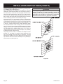
Location of Furnace
Pickalocationonanoutsidewallwithaclearspaceof28"(711mm)
highby49"(124cm)wideintheroom.
Locating Wall Opening
The furnace is to be located on an outside wall. Locate wall studs
so that wall opening will be located between wall studs. The wall
studscanbeusedforattachmentofwallmountingbracket.The
wall opening required as shown in Figure 3 is a diameter of 7 1/2
inches(191mm).
A template is provided in furnace carton for positioning furnace on
thewall.Also,refertoFigure3forpositioningthefurnaceonwall
and for locating gas line connection.
Figure 3willpositionthefurnacefourinches(102mm)offtheoor.
Ifitisdesiredtopositionthefurnacehigheronthewall,addthe
differencetothe"A,""B"and"C"dimensions.
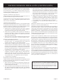
NOTE: The vent opening is not in the center of the furnace.
WALL MOUNTING
BRACKET
14”
(356 MM)
11”
(279 MM)
2”x4” (51 Mmx102 MM) STUDS
16” (406 MM)ON CENTER
C
19 3/4”
(502 MM)
4” (102 MM) MIN.
OUTER CASING
OF UNIT
15 1/2”
(394 MM)
37”
(940 MM)
17 3/4”
(451 MM)
21 1/2”
(546 MM)
GAS INLET
TO VALVE
7 1/2” (191 MM) DIA.
WALL OPENING
B
27 3/16”
(691 MM)
A
28”
(711MM)
Figure 3
DV-25-2 SHOWN
UNIT
IS SUPPORTED
BY
WALL BRACKET
4 ½”(114mm)MIN. WALL DV-25, DV-35
13” (330mm) MAX. WALL DV-25, DV
-35
MOUNTING PLATE
(CAULK UNDER FLANGE)
VENT CAP
FLUE OUTLET TUBE EXTENDS
2 ½”(64mm) BEYOND WALL
AIR INLET TUBE EXTENDS
½”(13mm) BEYOND WALL
OUTSIDE WALL
UNIT FASTENED TO WALL
WITH (2) SCREWS
4”
102mm
4”
102m
m
Figure 4
Installing Wall Mounting Bracket
Locate and cut wall opening. If there is insulation above the wall
opening(airinlettube)abarriershouldbeinstalledabovethewall
opening(airinlettube)topreventinsulationfromcomingincontact
with the air inlet tube. The barrier must not penetrate into the
7-1/2"(191mm)diameterwallopening.Placetheatsurfaceofthe
wallmountingbrackettowardthewall.Inserthalfroundangeof
wallmountingbracketintoandatthetopofthewallopening.The
halfroundangeofthewallmountingbracketmustbeincontact
withthesheetrockorwoodatthetopofthewallopening.Level
thewallmountingbracketinthewallopening.

37408-5-0919 Page 11
INSTALLATION INSTRUCTIONS (CONT'D)
Onsolidwall,whenusingwallstudsforattachmentofwallmounting
bracket,fastenwallmountingbrackettowallstudswith(2)#10x
11/2"(38mm)screwsprovidedandfasten(2)additional#10x1
1/2"(38mm)screwsprovidedthroughthewallmountingbracket
and into the solid wall.
Onsheetrock,whenusingwallstudsforattachmentofwallmounting
bracket,fastenwall mounting brackettowall studswith(2) #10
x11/2"(38mm)screwsprovidedandbyusingwallopeningfor
access,fasten2additional#10x11/2"(38mm)screwsand(2)
Tinnermannutsprovidedthroughthewallmountingbracketand
intothesheetrock.
Attaching Furnace To Wall Mounting Bracket
Hangfurnaceonwallmountingbracketbyaligning(2)tabsonwall
mountingbracketwith(2)slotslocatedoninnercasingtop.
Theinnercasingbottomistobefastenedtothewall.Onsolidwall,
fasteninnercasingbottomwith(2)#10x11/2"(38mm)screws
provided.Onsheetrockwall,fasteninnercasingbottomwith(2)
toggle bolts provided.
Cutting Vent Tubes
This is the most important part of the installation. With the furnace
installedonwallthe6"(152mm)diameterairinlettubeandthe4"
(102mm)diameterueoutlettubearetobemarkedandcutusing
the following procedure.
1. Attach6"(152mm)diameterairinlettubeontothecollarofair
dropassembly.Besure6"(152mm)diameterairinlettubeis
placed as far as possible onto the collar of the air drop assembly.
Markthe6"(152mm)diameterairinlettube1/2"(13mm)beyond
theoutsidewall.Remove6"(152mm)diameterairinlettube
from collar of air drop assembly.
2. Attach4" (102mm) diameter ue outlet tube onto ue outlet
collaroncombustionchamber.Besure4"(102mm)diameter
ueoutlettubeisplacedasfaraspossibleontothecollarof
ueoutlet.Markthe4"(102mm)diameterueoutlettube21/2"
(64mm)beyondtheoutsidewall.Remove4"(102mm)diameter
ueoutlettubefromcollarofueoutletoncombustionchamber.
3. Markorwraptapecompletelyaroundthetubesatthemarked
pointstohelpinmakingatruecut.Donotcrimporenlarge
tubes.
Installing Vent Assembly
1. Placecaulking(notprovided)beneaththeedgeoftheoutside
mountingplate.Useadditionalcaulkingtocorrectunevenwall
surface,suchasclapboard.
2. Attach6"(152mm)diameterairinlettubeontothecollarofair
drop assembly. Attach caulked, outside mounting plate into
the6"(152mm)diameter airinlettube. Position theoutside
mountingplatesothat6"(152mm)diameterairinlettubehas
a slight downward slope to the outside. The downward slope
is necessary to prevent the entry of rainwater. Attach outside
mountingplateto exteriorwall with(4)#10 x1 1/2"(38mm)
screws provided.
3. Applyfurnacecementto4"(102mm)diameterueoutletcollar
oncombustionchamberandto4"(102mm)diametercollaron
ventcap.Attach4"(102mm)diameterueoutlettubeontoue
outlet collar on combustion chamber. Attach vent cap into the 4"
(102mm)diameterueoutlettube.Attachventcaptooutside
mountingplatewith(3)#10x1/2"(13mm)screwsprovided.
4. Installation is completed.
Reassembly And Resealing Vent-Air Intake System
Whenvent-airintakesystemisremovedforservicingthefurnace,
the following steps will assure proper reassembly and resealing of
thevent-airintakeassembly.
1. Removeoldfurnacecementfromueoutletcollaroncombustion
chamber and collar of vent cap. Remove old furnace cement
frombothendsof4"(102mm)diameterueoutlettube.
2. Removeoldcaulkingbeneaththeedgeoftheoutsidemounting
plate. Apply new caulking beneath the edge of the outside
mountingplate.Useadditionalcaulkingtocorrectunevenwall
surface,suchasclapboard.
3. Attach6"(152mm)diameterairinlettubeontothecollarofair
drop assembly. Attach caulked, outside mounting plate into
the6"(152mm)diameter airinlettube. Position theoutside
mountingplatesothat6"(152mm)diameterairinlettubehas
a slight downward slope to the outside. The downward slope
is necessary to prevent the entry of rainwater. Attach outside
mountingplateto exteriorwall with(4)#10 x1 1/2"(38mm)
screws provided.
4. Applyfurnacecementto4"(102mm)diameterueoutletcollar
oncombustionchamberandto4"(102mm)diametercollaron
ventcap.Attach4"(102mm)diameterueoutlettubeontoue
outlet collar on combustion chamber. Attach vent cap into the 4"
(102mm)diameterueoutlettube.Attachventcaptooutside
mountingplatewith(3)#10x1/2"(13mm)screwsprovided.
5. Reassemblyandresealingvent-airintakesystemiscompleted.

37408-5-0919Page 12
INSTALLATION INSTRUCTIONS (CONT'D)
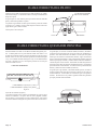
Installing a Vent Near a Window Ledge, Other Type of Projection
or on Siding (vinyl, aluminum, etc.)
Direct vent furnaces are designed to be installed on a uniform
outsidewall.Whenthewindcomesfromanyangle(up,downor
fromeitherside),itmusthittheventcapequallyoverboththeair
inletandtheueoutletportionsofthevent.Anywallprojection,
suchasadoororwindowcasing,whichdisturbsthewindonone
sideoftheairinletsectionwillresultinbackpressureontheue
sectionsmotheringtheameandeventualpilotoutage.
When the vent cap is to be installed on siding or it appears that
aprojectionwithin6"(152mm)ofanysideoftheairinletsection
couldshieldtheairinletsection,theentireventshouldbesupported
away from the wall at least the distance of the projection. 2" x
4" (51mm x 102mm) framing whose outside dimensions match
the overall dimensions of the mounting plate is recommended.
The2"x4"(51mmx102mm)framingprotectssidingfrompossible
warpage or discoloration. All joints can then be sealed and painted.
Thewalldepthplustheadditionaldepthofthe2"x4"(51mmx
102mm)framingshouldnotexceedatotaldepthof13"(330mm)
forDV-25andDV-35.(SeeFigure5)
Vinylsidingvent kit,DV-822, isavailable fromEmpire Comfort
Systems,Inc.Thedepthis 3"(76mm),whichenables thevent
cap to be extended away from siding or projections. The wall
depthplustheadditional3"(76mm)depthofthevinylsidingvent
capextensionshouldnotexceedatotaldepthof13"(330mm)for
DV-25andDV-35.(SeeFigure5a)
WARNING
When vinyl siding vent kit, DV-822 or 2" x 4" (51mm x 102mm)
framing is added to an existing installation (furnace is
both tubes. Refer to Parts List, page 16 to order tubes.
Figure 5a
Figure 5

37408-5-0919 Page 13
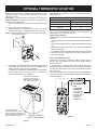
OPTIONAL THERMOSTAT LOCATION
Millivolt wall thermostats are specially designed for use on self-
generating systems. They should never be used on line or low
voltage A.C. circuits.
Interior Wall - The thermostat can be installed on an inside wall.
Thermostat Bracket - The thermostat can also be attached to the
unitwiththeprovidedbracket.
1. Determine which side of the unit the thermostat will be secured
to.
2. Remove the front of the thermostat.
3. Attach thermostat to the bracket using the two (2) screws
provided. See Figure 6. Replace the front of the thermostat.
NOTE: Bracketinstallationisoptional.Donotuseifnotinstalling
an optional thermostat.
Figure 6
4. Ifinstallingthethermostatbracketaftertheunithasbeeninstalled,
drill a hole in the side of the unit as shown in Figure 7. and
attachthebracketwithascrew(notprovided).
Ifinstallingthethermostatbracketbeforetheunitisinstalled,
usetheexistingscrewonthebackoftheunittoattachthe
brackettotheunitasshowninFigure 7.
IF BRACKET IS INSTALLED
AFTER UNIT IS IN PLACE,
DRILL HOLE INTO CASING
SIDE AND ATTACH HERE.
USE
THIS EXISTING
SCREW
(ON EITHER SIDE
OF
THE HEATER) TO MOUNT
BRACKET
IF INSTALLING BEFORE
UNIT
IS AGAINST THE WALL.
PARTIAL VIEW OF
LEFT REAR
CORNER
Figure 7
Wire Gauges - It is important to use wire of a gauge proper for the
lengthofthewire:
RECOMMENDED WIRE GAUGES
Maximum Length Wire Gauge
1'to10' 18
10'to25' 16
25'to35' 14
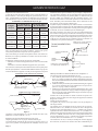
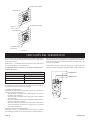
Properoperationdependsonagoodpilotame.Theamemust
coverthetopofthethermopile.Cleaningofthepilotoriceand
burner may be required due to spiders.
System Check (Figure 8)
Amillivoltmeterisrequiredtocheckthesystem.Millivoltreadings
shouldbe:
• Acrossthethermopileterminals,400-450millivoltswiththermostat
OFF.
• Acrossthethermopileterminals,150-250millivoltswiththermostat
ON.
• Acrossthethermostatwiresatthevalve,lessthan30millivolts
with thermostat ON.
• Acrossthethermostatwiresatthethermostat,lessthan5millivolts
with thermostat ON.(Strongwinds,dirtypilotandlowpressure
will reduce readings.)
Depressingtheredbuttoncompletelycausesasparktooccurat
the pilot. This is a substitute for a match which requires opening
the pilot hole cover.
Tolightthepilot,itisimportantthattheelectrodebe1/8"(3mm)
fromthethermopile.Thesparkmustoccuratthepointtheburner
amehitsthethermopile.Theendoftheelectrodewillberedhot
with the pilot on.
Onanewinstallationwithairinthegasline,itissuggestedthata
match be used. The match will light the pilot faster than the piezo
under this condition.
Figure 8
NOTE:
TO OPTIONAL
THERMOSTAT
IS CONNECTED
WITH WIRE NUT
FROM FACTORY.
DISCONNECT
TO ATTACH
THERMOSTAT.

37408-5-0919Page 14
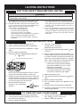
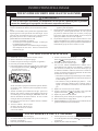
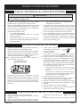
FOR YOUR SAFETY READ BEFORE LIGHTING
A. This appliance has a pilot which must be lighted by hand.
Whenlightingthepilot,followtheseinstructionsexactly.
B. BEFORE LIGHTING smell all around the appliance area
forgas.Besuretosmellnexttotheoorbecausesome
gasisheavierthanairandwillsettleontheoor.
WHAT TO DO IF YOU SMELL GAS
•Donottrytolightanyappliance.
•Donottouchanyelectricalswitch;
do not use any phone in your building.
•Immediatelycallyourgassupplierfromaneighbor's
phone.Followthegassupplier'sinstructions.
•Ifyoucannotreachyourgassupplier,callthere
department.
C. Use only your hand to push in or turn the gas control
knob.Neverusetools.Iftheknobwillnotpushinor
turnbyhand,don'ttrytorepairit;callaqualiedservice
technician. Force or attempted repair may result in a
reorexplosion.
D. Do not use this appliance if any part has been under
water.Immediatelycallaqualiedservicetechnician
to inspect the appliance and to replace any part of the
control system and any gas control which has been
under water.
TO TURN OFF GAS TO APPLIANCE
1. Setthethermostattolowestsetting(ifapplicable).
2. Turn off all electric power to appliance if service is to
beperformed(ifapplicable).
3. Remove casing front assembly.
4. Pushingascontrolknobslightlyandturnclock-
wise to "OFF." Do not force.
5. Replace casing front assembly.
1. STOP! Read the safety information above.
2. Setthethermostattolowestsetting(ifapplicable).
3. Turnoffallelectricpowertotheappliance(ifappli-
cable).
4. Remove casing front assembly.
5. Pushingascontrolknobslightlyandturnclockwise
to "OFF".
NOTE:Knobcannotbeturnedfrom"PILOT"to"OFF"
unlessknobispushedinslightly.Donotforce.
6. Waitten(10)minutestoclearoutanygas.Thensmell
forgas, including neartheoor.If you smellgas,
STOP! Follow "B" in the safety information above. If
youdon'tsmellgas,gotothenextstep.
7. Remove the pilot access cover
located on the combustion
chamber.
8. Find pilot - follow metal tube
from gas control. The pilot is
behind the pilot access cover.
9. Turnknobongascontrolcounterclockwise
to "PILOT."
10.Pushincontrolknoballthewayandholdin.Im-
mediately light the pilot with the Piezo Pilot Ignitor
oramatch.Continuetoholdthecontrolknobinfor
aboutone(1)minuteafterthepilotislit.Release
knob,anditwillpopbackup.Pilotshouldremain
lit.Ifitgoesout,repeatsteps5through10.
•Ifknobdoesnotpopupwhenreleased,
stop and immediately call your service
technician or gas supplier.
•Ifthepilotwillnotstaylitafterseveraltries,
turnthegascontrolknobto"OFF"andcall
your service technician or gas supplier.
11. Replace pilot access cover.
12.Turngascontrolknobcounterclockwise to
"ON."
13. Replace casing front assembly.
14.Turnonallelectricpowertotheappliance(ifap-
plicable).
15.Setthermostattodesiredsetting(ifapplicable).
16.CAUTION:Pilotaccesscovermustbekepttightly
closed during operation.
LIGHTING INSTRUCTIONS
LIGHTING INSTRUCTIONS
GAS CONTROL KNOB SHOWN IN “OFF”
POSITION
WARNING
personal injury or loss of life.

37408-5-0919 Page 15
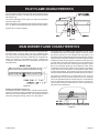
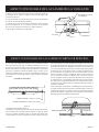
Thecorrectamewillbealmosthorizontal,blueandwillextendpast
thethermopile1/4"(6mm).Theamewillsurroundthethermopile
just below the tip.
OnPropaneGasslightyellowmightoccurwherethepilotame
andburneramemeet.
Natural Gas pilots require adjusting when the inlet pressure is above
5"w.c.(1.25kPa)Turnadjustmentscrewclockwisetoreduceame.
Propane will not require adjusting.
Figure 9
Therewillbeashortblueinneramewithamuchlargerlighterblue
secondaryame.Theburneramemayhaveayellowtipwhen
hot. See the burner drawing showing the approximate heights of
eachpartoftheame.Dustinthecombustionairwillproducean
orangeorredame.Donotmistaketheorangeorredamefor
animproperyellowame.Afteruse,cleaningmayberequiredfor
theproperame.
Figure 10
Primary Air Adjustment (Figure 11)
An air adjustment bolt is located on the chamber support bottom.
Thefourinch(102mm)clearancebetweenthefurnaceandtheoor
allows access to the air adjustment bolt. The air adjustment bolt is
above the rectangular opening on the inner casing bottom.
OnPropanegas,ifawhistlingnoise (resonation)occurs,screw
air adjustment bolt into the chamber support in order to reduce
theamountofprimaryair.Ifthewhistlingnoise(resonation)isnot
eliminated when the air adjustment bolt is screwed into the chamber
support this may indicate the air adjustment bolt is misaligned. Grasp
airadjustmentboltandpivot(push)airadjustmentboltawayfrom
yourself.Observethemainburnerameasyoupushairadjustment
boltandwhenthemainburneramebeginstodevelopayellow
ame,youshouldstoppushingontheairadjustmentbolt.Screw
airadjustmentboltoutofthechambersupportuntiltheyellowame
on the main burner is eliminated. The air adjustment bolt should
now be properly aligned. The reduction in primary air will soften the
mainburnerameandwilleliminatethewhistlingnoise(resonation).
OnPropane or NaturalGas, ifa yellowame occurs,screw air
adjustment bolt out of the chamber support but do not completely
remove air adjustment bolt from chamber support. The repositioning
of the air adjustment bolt will increase the amount of primary air.
Theincreaseinprimaryairwillsharpenthemainburnerameand
willeliminatetheyellowame.
Figure 11
PILOT FLAME CHARACTERISTICS
MAIN BURNER FLAME CHARACTERISTICS

37408-5-0919Page 16
Removing Main Burner
1. Disconnect the thermopile and pilot supply line at the pilot burner.
2. Remove the burner compartment cover.
3. Removeoriceshield.
4. Remove bolt on each side of burner and lift out.
Cleaning Main Burner
The main burner may be cleaned by forcing water into the ports
and the throat of the burner. The main burner should be blown dry
or heated to remove water from main burner.
1. Open the brass union located after the gas valve.
2. Loosenvalvebracket.
3. Removethe3/8"(10mm)manifoldpipethatisattachedtothe
union elbow until the manifold pipe is free.
4. Themainburneroriceisattheendofthemanifoldpipe.
1. Disconnect the pilot supply line at the pilot burner.
2. Removepilotoricefrompilotburner.Itmaybenecessaryto
taponpilotburnerinordertoremovethepilotorice.
Afteruse,cleaningofthepilotburnermayberequiredfortheproper
ame.Also,cleaningofthepilotburnermayberequireddueto
spiders(spiderwebs).Thepilotoricecanbecleanedwithhigh
pressureairorbyplacingunderrunningwater.Pilotoricemust
be dry before replacement. Use a pipe cleaner to clean inside the
pilotafterthepilotoricehasbeenremoved.
Cleaning Combustion Chamber
When the main burner and vent cap are removed, all internal
areas of the combustion chamber are accessible for cleaning with
a vacuum hose.
MAINTENANCE
1. Lit match goes out as it enters lighter port.
a.Certainwindconditionswillblowoutmatch.Ignitematch,
andasitares,thrustmatchthroughopening.
b. Open nearby door or window and relight pilot.
2.Pilotamesbutgoesoutwhenknobisreleased.
a. See Lighting Instructions. Relight Pilot.
b.Relightthepilotandholdknobdownlongerandharder.Close
lighterholecoverjustafterigniting.Checkforagoodpilot
ame.
c. Defective thermopile or defective magnet in safety section
of valve. Replace.
3.Yellowpilotame
a.Obstructionatpilotorice.
b.Cleanpilotorice.
4. Pilot and main burner go out during normal operation.
a.Checkmillivolts.
b.Checkforpropersizeofpilotame.
c. Checkfordefectiveorweakthermopile.
d. Checkinput,reduceasneeded.
e. Cover on pilot lighter hole must be air tight.
f. Checkfortighttofairanduetubesatbothendsofvent
assembly. No obstruction around vent that would prevent
the wind from hitting all of the vent equally.
5. Thermostat does not turn the main burner on.
a.Checkwiring.
b.Checkallmillivoltreadings.
c. Checkforspiderinmainburnerorice.
6.Yellowmainburneramesootontheventcap.
a. SeePage13,"PrimaryAirAdjustment".
b.Removemainburnertocheckforobstructionsinthroatand
ports.
c. Installnewmainburneroriceandpilotorice.RefertoParts
List,page16.
7. OnPropaneGas,ifawhistlingnoise(resonation)occurs.
a. SeePage13,"PrimaryAirAdjustment".
b. Reduce manifold pressure.
c. Sizemainburneroricewithadrillbit.ForDV-25use1.45mm
drillbit.ForDV-35use#50drillbit.
TROUBLESHOOTING

37408-5-0919 Page 17
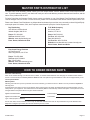
ToOrderPartsUnderWarranty,pleasecontactyourlocalEmpiredealer.Seethedealerlocatoratwww.empirecomfort.
com.Toprovidewarrantyservice,yourdealerwillneedyournameandaddress,purchasedateandserialnumber,andthe
nature of the problem with the unit.
ToOrderPartsAftertheWarrantyPeriod,pleasecontactyourdealeroroneoftheMasterPartsDistributorslistedbelow.
Thislistchangesfromtimetotime.Forthecurrentlist,pleaseclickontheMasterPartsbuttonatwww.empirecomfort.com.
Pleasenote:MasterPartsDistributorsareindependentbusinessesthatstockthemostcommonlyorderedOriginalEquip-
mentrepairpartsforHeaters,Grills,andFireplacesmanufacturedbyEmpireComfortSystemsInc.
MASTER PARTS DISTRIBUTOR LIST
Parts Not Under Warranty
PartscanbeorderedthroughyourServicePerson,Dealer,oraMasterPartsDistributor.SeethispagefortheMasterPartsDistribu-
torslist.Forbestresults,theservice person or dealer should order parts through the distributor. Parts can be shipped directly to the
service person/dealer.
Warranty Parts
Warranty parts will need a proof of purchase and can be ordered by your Service Person or Dealer. Proof of purchase is for
warranty parts.
AllpartslistedinthePartsListhaveaPartNumber.Whenorderingparts,rstobtaintheModelNumberandSerialNumberfromthe
nameplateonyourequipment.ThendeterminethePartNumber(not the Index Number) and the Description of each part from the fol-
lowing illustration and part list. Be sure to give all this information . . .
Appliance Model Number Part Description
Appliance Serial Number Part Number
TypeofGas(PropaneorNatural)
Donotorderbolts,screws,washersornuts.Theyarestandardhardwareitemsandcanbepurchasedatanylocalhardwarestore.
Shipmentscontingentuponstrikes,resandallcausesbeyondourcontrol.
HOW TO ORDER REPAIR PARTS
Dey Distributing
1401WillowLakeBoulevard
VadnaisHeights,MN55101
Phone: 651-490-9191
Toll Free: 800-397-1339
Website: www.deydistributing.com
Parts: Heater, Hearth and Grills
F. W. Webb Company
200 Locust Street
Hartford,CT06114
Phone: 860-722-2433
Toll Free: 800-243-9360
Fax: 860-293-0479
Toll Free Fax: 800-274-2004
Websites: www.fwwebb.com & www.victormfg.com
Parts: Heater, Hearth and Grills
East Coast Energy Products
10 East Route 36
WestLongBranch,NJ07764
Phone: 732-870-8809
Toll Free: 800-755-8809
Fax: 732-870-8811
Website: www.eastcoastenergy.com
Parts: Heater, Hearth and Grills

37408-5-0919Page 18
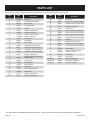
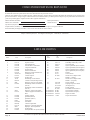
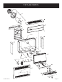
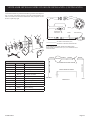
PLEASENOTE:Whenorderingparts,itisveryimportantthatpartnumberanddescriptionofpartcoincide.
USEONLYMANUFACTURER'SREPLACEMENTPARTS.USEOFANYOTHERPARTSCOULDCAUSEINJURYORDEATH.
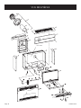
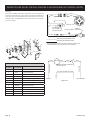
PARTS LIST
Index
No.
Part
No.
Description
1 DV769 Vent Cap
2 DV131 Outside Mounting Plate
3 DV548 Air Inlet Tube
4 DV524 Flue Outlet Tube
5 DV757 VentKit
6 DV899 WallMountingBracket
7 DV900 Inlet Air Drop Chute
8
DV762
& DV763
Gasket-AirDropChute
(2EachRequired)
9 DV951 Casing Top
10 DV901 Heat Shield
11 32143 Inner Casing
12 RH705 CasingSide(2Required)
13 M96 Gasket-FlueOutletSupport
14 DV903 CombustionChamber(DV25)
14 DV904 CombustionChamber(DV35)
15 M155 Gasket-LightingHole
16 DV781
Lighting Hole Cover Assembly
with Clear Mica
17 DV064 Cover Plate
18 DV988 Burner(DV25)
18 DV990 Burner(DV35)
19 R942 Thermopile
20 DV1004 Pilot Tubing w/Ferrells
21 RH238 Burner Door
22 DV778 Gasket-BurnerDoor
23 M151 Gasket-PilotBurner
24 DV994 Pilot Shield
25 R2224
PilotBurnerwithOrice(Natural)
25 R2223
PilotBurnerwithOrice(Propane)
26 DV772 Electrode and Wire
27 DV913 Casing Front
28 P8643 BurnerOrice,(DV25Natural)
28 P86145 BurnerOrice,(DV25Propane)
28 P8638 BurnerOrice,(DV35Natural)
28 P8650 BurnerOrice,(DV35Propane)
29 P190 Manifold
30 P191 Manifold Union Assembly
31 R5600
GasValve(Natural)7000MVRLC
31 R5601
GasValve(Porpane)7000MVRLC
32 DV1003 ValveBracket
33
DV764
& DV765
Gasket-ChamberSupport
(2EachRequired)
34 DV908 Valve Shield
35 R2708 Piezo Ignitor
Not Shown R1081 PilotOrice(Natural)
Not Shown R1089 PilotOrice(Propane)
Not Shown DV885 HardwarePackage
Index
No.
Part
No.
Description

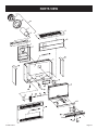
37408-5-0919 Page 19
PARTS VIEW

37408-5-0919Page 20
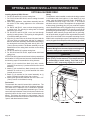
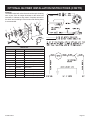
OPTIONAL BLOWER DRB-1
Installing Optional DRB-1 Blower
1. ForRH-25andRH-35,removecasingfront.
1. ForDV-25-SGandDV-35-SG,removecasingfrontand
heat shield.
2. Whenfacingappliance,insertblowerassemblyintothe
left section of the casing (adjacent to the combustion
chamber).
3. ForRH-25andRH-35,routecordsetthroughopening
incasing back.Theopening in casingback islocated
adjacent to gas control.
3. For DV-25-SG and DV-35-SG, route cord set through
opening in casing bottom. The opening in casing bottom
is located beneath gas control.
4. Alignthe(2)screwholesontheinnersidepanelandthe
(2)screwholes on casing backwiththe(4) clearance
holes on the blower assembly. Attach blower assembly to
thecasingbackandinnersidepanelwith(4)#10x1/2"
(13mm)screwsprovided.Theblowerassemblymustbe
attachedrsttothecasingbackandthentothecasing
side panel.
5. ForRH-25andRH-35,replacecasingfront.
5. ForDV-25-SGandDV-35-SG,replaceheatshieldand
casing front.
ATTENTION:Wiringharnessonblowerisfactoryassembled
and installed. If wiring harness becomes disassembled use
the following steps to reassemble the wiring harness.
1. Attach (1) pin terminal from black (hot) wire, smooth
insulationoncordsetto(1)socketterminalonfancontrol
assembly.
2. Attach(1)pinterminalfromblack(neutral)wire,ribbed
insulationoncordsetto(1)socketterminalfromwhite
(neutral)wireonmotor.
3. Attach (1) pin terminal on fan control assembly to (1)
socketterminalfromblack(hot)wireonmotor.
4. Attachgreengroundwirebeneathoneofthe#10x1/2"
(13mm)screwsontheblowerhousing.
Fan Control
The automatic fan control is located in the switch box. The
switch box is attached to the front of the blower assembly.
The switch box is adjacent to the combustion chamber.
The fan control is a non-adjustable automatic type. The fan
control will require between 5 and 10 minutes of main burner
operation before the fan control "closes" and activates the
blower. The blower will continue to run between 5 and 10
minutesafterthemainburnershutsoff,beforethefancontrol
"opens" and deactivates the blower.
Wiring
Theappliance,wheninstalled,mustbeelectricallygrounded
inaccordancewithlocalcodesor,intheabsenceoflocal
codes, with the National Electrical Code, ANSI/NFPA 70
or Canadian Electrical Code, CSA C22.1, if an external
electrical source is utilized. This appliance is equipped with
a three-prong [grounding] plug for your protection against
shockhazardandshouldbepluggeddirectlyintoaproperly
grounded three-prong receptacle. Do not cut or remove the
groundingprongfromthisplug.Foranungroundedreceptacle,
anadapter,whichhastwoprongsandawireforgrounding,
canbepurchased,pluggedintotheungroundedreceptacle
and its wire connected to the receptacle mounting screws.
Withthiswirecompletingtheground,theappliancecordplug
can be plugged into the adapter and be electrically grounded.
CAUTION
Label all wires prior to disconnection when servicing
controls. Wiring errors can cause improper and dangerous
operation. Verify proper operation after servicing.
WARNING
Unplugging of blower accessory will not stop the heater
from cycling. To shut heater off: Turn temperature dial
or thermostat to lowest setting. Turn knob on gas
control to "OFF", depressing slightly. Do not force.
OPTIONAL BLOWER INSTALLATION INSTRUCTIONS
La page est en cours de chargement...
La page est en cours de chargement...
La page est en cours de chargement...
La page est en cours de chargement...
La page est en cours de chargement...
La page est en cours de chargement...
La page est en cours de chargement...
La page est en cours de chargement...
La page est en cours de chargement...
La page est en cours de chargement...
La page est en cours de chargement...
La page est en cours de chargement...
La page est en cours de chargement...
La page est en cours de chargement...
La page est en cours de chargement...
La page est en cours de chargement...
La page est en cours de chargement...
La page est en cours de chargement...
La page est en cours de chargement...
La page est en cours de chargement...
La page est en cours de chargement...
La page est en cours de chargement...
La page est en cours de chargement...
La page est en cours de chargement...
La page est en cours de chargement...
La page est en cours de chargement...
La page est en cours de chargement...
La page est en cours de chargement...
La page est en cours de chargement...
La page est en cours de chargement...
La page est en cours de chargement...
La page est en cours de chargement...
La page est en cours de chargement...
La page est en cours de chargement...
La page est en cours de chargement...
La page est en cours de chargement...
La page est en cours de chargement...
La page est en cours de chargement...
La page est en cours de chargement...
La page est en cours de chargement...
La page est en cours de chargement...
La page est en cours de chargement...
La page est en cours de chargement...
La page est en cours de chargement...
-
 1
1
-
 2
2
-
 3
3
-
 4
4
-
 5
5
-
 6
6
-
 7
7
-
 8
8
-
 9
9
-
 10
10
-
 11
11
-
 12
12
-
 13
13
-
 14
14
-
 15
15
-
 16
16
-
 17
17
-
 18
18
-
 19
19
-
 20
20
-
 21
21
-
 22
22
-
 23
23
-
 24
24
-
 25
25
-
 26
26
-
 27
27
-
 28
28
-
 29
29
-
 30
30
-
 31
31
-
 32
32
-
 33
33
-
 34
34
-
 35
35
-
 36
36
-
 37
37
-
 38
38
-
 39
39
-
 40
40
-
 41
41
-
 42
42
-
 43
43
-
 44
44
-
 45
45
-
 46
46
-
 47
47
-
 48
48
-
 49
49
-
 50
50
-
 51
51
-
 52
52
-
 53
53
-
 54
54
-
 55
55
-
 56
56
-
 57
57
-
 58
58
-
 59
59
-
 60
60
-
 61
61
-
 62
62
-
 63
63
-
 64
64


Empire Heating Systems Direct-Vent Wall Furnace (DV25/35) Le manuel du propriétaire
- Taper
- Le manuel du propriétaire
dans d''autres langues
Documents connexes
-
Empire Heating Systems Direct-Vent Wall Furnace (DV25/35) Le manuel du propriétaire
-
Empire Heating Systems DV-40E-5 Le manuel du propriétaire
-
Empire Heating Systems Direct-Vent Wall Furnace (DV210/215) Le manuel du propriétaire
-
-
-
-
-
-
-
Autres documents
-
Empire DV-25-4SG Installation Instructions And Owner's Manual
-
-
Lambro FBA_361W Guide d'installation
-
-
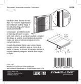 Prime-Line B 705 Mode d'emploi
-
Empire DVC-35-2IP Le manuel du propriétaire
-
Legrand CCA6W Guide d'installation
-
Vita Springwood Arbor Mode d'emploi
