Tripp Lite SmartPro, 1920W Manuel utilisateur
- Catégorie
- Alimentations sans interruption (UPS)
- Taper
- Manuel utilisateur
Ce manuel convient également à

1
Owner’s Manual
1111 W. 35th Street, Chicago, IL 60609 USA • www.tripplite.com/support
Copyright © 2012 Tripp Lite. All rights reserved. SmartPro® is a registered trademark of Tripp Lite.
SMART2500XLHG
(AG-8589)
Intelligent, Line-Interactive,
Medical-Grade UPS System
Full Isolation: Less than 100µA leakage
Important Safety Instructions 2
Package Contents 3
Quick Installation 4
User Interface 5
Optional Installation 5
Basic Operation 7
Guidance and Manufacturer’s Declaration 10
Storage and Service 12
Battery Replacement 12
Warranty Registration 13
Español 14
Français 27
WARRANTY
REGISTRATION
Register online today for a
chance to win a FREE Tripp Lite
product! www.tripplite.com/warranty
12-10-307-93-3181.indb 1 11/2/2012 9:27:37 AM

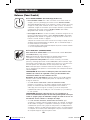
2
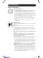
Important Safety Instructions
Statement of Intended Use
Tripp Lite Medical-Grade UPS Systems are intended to support and protect non-medical
computer equipment and medical devices that require leakage current reduction, surge
protection, voltage regulation, line noise filtering and battery backup during power outages and
generator testing, both inside and outside patient care areas. Tripp Lite’s Medical-Grade UPS
Systems come with hospital-grade plugs and receptacles that reduce leakage to below 100µA.
SAVE THESE INSTRUCTIONS
This manual contains important instructions that should be followed during the installation,
operation and storage of all Tripp Lite UPS Systems. Failure to heed these warnings will void
your warranty.
Note: Your UPS incorporates fusing only in the ungrounded phase conductor. UL 60601-1 certified UPS
systems must not be used in countries other than the United States and Canada and must be used only in
healthcare facilities on grounded systems where conditions of maintenance and supervision ensure that only
qualified persons will service the electrical distribution system.
UPS Location Warnings
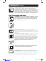
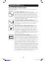
• Relevantsymbols
Denotes that information in the manual should be reviewed before use.
Used to signal as a warning that a statement is particularly important and could pose
a safety risk.
Denotes that instructions should be followed for proper use.
Warns that users should not sit or step on the unit.
Indicates that you should not push the unit.
• Donotusethisequipmentwithinoxygen-enrichedatmospheres,orwithin0.3m(1ft.)ofa
pointatwhichanoxygen-enrichedatmosphereisintentionallyvented.
• UsecautionwhenliftingUPS.BecauseoftheconsiderableweightofallUPSsystems,at
least two people should assist in lifting and installing them.
• InstallyourUPSindoors,awayfromexcessmoistureorheat,dustordirectsunlight.
•Forbestperformance,theUPSshouldbeusedinalocationthatmeetsthefollowing
conditions:Temperature:0to40°C(32to104°F);Humidity:0to95%(non-condensing);
Elevation:<6,562ft.(2,000m)abovesealevel;Pressure:<95kPA
• LeaveadequatespacearoundallsidesoftheUPSforproperventilation.Donotobstructits
vents or fan openings.
UPS Connection Warnings
•TheUPScontainsitsownenergysource(battery).Theoutputterminalsmaybeliveeven
when the UPS is not connected to an AC supply.
•ConnectyourUPStoaproperlygroundedACpoweroutlet.DonotmodifytheUPS’splugin
a way that would eliminate the UPS's connection to ground. Do not use adapters that
eliminate the UPS’s connection to ground.
•DonotplugyourUPSintoitself;thiswilldamagetheUPSandvoidyourwarranty.
•IfyouareconnectingyourUPStoamotor-poweredACgenerator,thegeneratormustprovide
filtered, frequency-regulated computer-grade output. Connecting your UPS to a generator will
void its Ultimate Lifetime Insurance.
12-10-307-93-3181.indb 2 11/2/2012 9:27:37 AM

3
Important Safety Instructions
•ToisolatetheUPSfromthesupplymains,disconnecttheinputplug.
• Onceconnected,donotlimitaccesstotheinputplug.Theplugmustbeaccessibletobe
used as a means of disconnection.
• CAUTION: To ensure proper grounding, the input cord must remain connected to the
supply mains at all times.
• WARNING: No modification of this equipment is allowed.
•UPSdoesnotrequiremaintenance.Therearenouserserviceableparts.
Equipment Connection Warnings
•DonotuseTrippLiteUPSSystemsforlifesupportapplicationsinwhichamalfunctionor
failure of a Tripp Lite UPS System could cause failure or significantly alter the performance of
a life-support device.
•DonotconnectsurgesuppressorsorextensioncordstotheoutputofyourUPS.Thismight
overload the UPS and will void the surge suppressor and UPS warranties.
CAUTION: The unit is for exclusive interconnection with IEC6060-1 certified
equipment in the patient environment and IEC 60950 certified equipment
outside of the patient environment. Do not contact SIP/SOP (such as the USB
port, RS232 port, etc.) and the patient at the same time.
Battery Warnings
•Batteriescanpresentariskofelectricalshockandburnfromhighshort-circuitcurrent.
Observeproperprecautions.Donotdisposeofthebatteriesinafire.DonotopentheUPS
or batteries. Do not short or bridge the battery terminals with any object. Unplug and turn off
theUPSbeforeperformingbatteryreplacement.Batteryreplacementshouldbeperformed
only by authorized service personnel using the same number and type of batteries (sealed
Lead-Acid). The batteries are recyclable. Refer to your local codes for disposal requirements
orintheUSAonlycall1-800-SAV-LEADor1-800-8-BATTERY(1-800-822-8837)orvisit
www.rbrc.com for recycling information. Tripp Lite offers a complete line of UPS System
ReplacementBatteryCartridges(R.B.C.).VisitTrippLiteontheWebatwww.tripplite.comto
locate the specific replacement battery for your UPS.
•Duringhot-swapbatteryreplacement,theUPSwillnotprovidebackuppowerintheeventof
a blackout or other power interruptions.
•DonotoperateUPSwithoutbatteries.
UPS Disposal
• Alwayscomplywithlocalordinancesforpropermethodsofrecyclinganddisposalof
electronic equipment.
• WhenpurchasinganewUPSfromTrippLite,youmaysendanoldUPSbackforrecyclingon
a one-for-one, like-for-like basis. The new equipment should also be sent back to Tripp Lite
when it ultimately becomes waste.
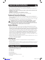
Package Contents
• SMART2500XLHGIntelligent,Line-Interactive,Medical-GradeUPSSystem
• ACPowerCord(C19toNEMA5-20P)
• 6-ft.DB9Cable
• 6-ft.USBCable
• 6-ft.RJ11Cable
• GroundingThumbscrew
• PowerCordRetentionBracketandScrew
• UserManual
12-10-307-93-3181.indb 3 11/2/2012 9:27:37 AM

4
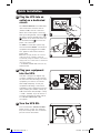
Quick Installation
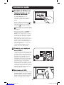
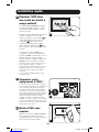
1 Plug the UPS into an
outlet on a dedicated
circuit.
TheSMART2500XLHGhasanIECC20
inlet to which the included cord set
(C19 to 5-20P) must be connected.
Attach the included power cord to the
UPS by inserting the IEC connector A of
the power cord into the IEC power inlet
B located on the back of the UPS. Use
the included bracket C to secure the
power cord connection.
UL 60601-1 listed UPS systems only
meet UL standard 60601-1 for medical
equipmentwhenpluggedintoanNEC
517approvedandinstalledmedical-
grade outlet.
Note: After you plug the UPS into a live AC
outlet, the UPS (in “Standby” mode) will
automatically charge its batteries,* but will not
supply power to its outlets until it is turned ON
(see Step 3 below).
* The BATTERY CHARGE LED will be the only
LED illuminated.
2 Plug your equipment
into the UPS.
YourUPSisdesignedtosupportonly
electronicequipment.Youwilloverload
the UPS if the total VA ratings for all the
equipmentyouconnectexceedsthe
UPS'sOutputCapacity.Tofindyour
equipment's VA ratings, look on their
nameplates. If the equipment is listed in
amps, multiply the number of amps by
120todetermineVA.(Example:1amp
× 120 = 120 VA). If you are unsure if
you have overloaded the UPS's outlets,
see“OUTPUTLOADLEVEL”LED
description.
3 Turn the UPS ON.
Pressandholdthe“ON/OFF/STANDBY”
button for one second. The alarm will
beep once briefly after one second has
passed. Release the button.
1
1
2
3
A
B
C
12-10-307-93-3181.indb 4 11/2/2012 9:27:39 AM

5
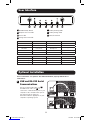
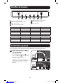
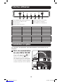
User Interface
A On/Off/StandbyButton
B OutputLoadLevelLEDs
C Power LED
D Voltage Correction LED
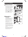
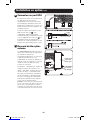
Optional Installation
These connections are optional. Your UPS will function properly without these
connections.
1 USB and RS-232 Serial
Communications
UsetheincludedUSBcable(see1a)
andDB9serialcable(see1b) to
connect the communication port on your
computer to the communication port of
your UPS. Install the Tripp Lite
PowerAlert Software appropriate to your
computer’s operating system.
Load Level States LED Indicator Audible Alarm
0-75% Line, Invert Green —
76-100% Line, Invert Yellow —
101-110% Line, Invert BlinkingRed —
>110% Line Red —
>110% Invert Red On
Runtime Condition States LED Indicator Audible Alarm
>3minremaining Invert Green —
3-2minremaining Invert Yellow —
<2 min remaining Invert Red On
E BatteryWarningLEDs
F BatteryChargeLEDs
G Mute/TestButton
A B C D E F G
1a
1b
12-10-307-93-3181.indb 5 11/2/2012 9:27:43 AM

6
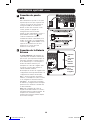
Optional Installation
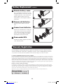
2 EPO Port Connection
This optional feature is only for those
applications which require connection to
afacility’sEmergencyPowerOff(EPO)
circuit. When the UPS is connected to
this circuit, it enables emergency
shutdown of the UPS’s inverter.
Using the cable provided, connect the
EPOportofyourUPS(see2a) to a user-
supplied normally closed or normally
open switch according to the circuit
diagram (see 2b).TheEPOportisnota
phonelinesurgesuppressor;donot
connect a phone line to this port.
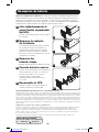
3 External Battery
Connection
TheSMART2500XLHGisequippedwith
anexternalbatterycapabilityfor
applicationsneedingextendedruntime.
The back of the unit includes the
externalbatterypackconnectorand
charger rate switch. To access the
connector, its factory-installed cover
must be removed.
The charger rate switch is set to the
internalbatterysetting(INT.BATT)by
default.Whenusinganexternalbattery
pack, the switch needs to be set to
externalbatterysetting(EXT.BATT).The
connection of a battery pack and setting
the switch can be done while the unit is
operational.
Note: Leaving the charger rate switch on INT.
BATT while connected to an external battery
will not damage the unit. However, it will
extend the time needed to recharge the
batteries after a power event.
2a
4-5
2b
3
External
Battery
Connector
Cover
Charger
Rate
Switch
12-10-307-93-3181.indb 6 11/2/2012 9:27:46 AM

7
Buttons (Front Panel)
Basic Operation
“ON/OFF/STANDBY” Button
• To turn the UPS ON: With the UPS plugged into a live AC wall outlet*,
pressandholdthe“ON/OFF/STANDBY”buttonforonesecond.**Release
thebutton.Ifutilitypowerisabsent,youcan“cold-start”theUPS
(i.e.:turnitONandsupplypowerforalimitedtimefromitsbatteries***)
bypressingandholdingthe“ON/OFF/STANDBY”buttonforonesecond.**
• To turn the UPS OFF: WiththeUPSONandreceivingutilitypower,press
andholdthe“ON/OFF/STANDBY”buttonforonesecond.**Thenunplug
theUPSfromthewalloutlet.TheUPSwillbecompletelyOFF.
* After you plug the UPS into a live AC outlet, the UPS (in ”Standby” mode) will
automatically charge its batteries, but will not supply power to its outlets until it is
turned ON.
** The alarm will beep once briefly after the indicated interval has passed.
*** If fully charged.
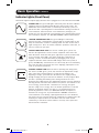
“MUTE/TEST” Button
To Silence (or “Mute”) UPS Alarms:BrieflypressandreleasetheMUTE/
TEST button.
Note: To permanently disable audible UPS alarms: Contact Tripp Lite support for
instructions.
To Run a Self-Test: WithyourUPSpluggedinandturnedON,pressand
hold the MUTE/TEST button. Continue holding the button until the alarm
beeps several times and the UPS performs a self test. See “Results of a
Self-Test”below.
Note: you can leave connected equipment on during a self-test. Your UPS, however,
will not perform a self-test if the UPS is not turned on (see “ON/OFF/STANDBY” Button
description).
CAUTION! Do not unplug your UPS to test its batteries. This will
remove safe electrical grounding and may introduce a damaging
surge into your network connections.
Results of a Self-Test: Thetestwilllastapproximately10secondsasthe
UPS switches to battery to test its load capacity and battery charge.
•Ifthered“OUTPUTLOADLEVEL”LEDremainslitandthealarmcontinues
to sound after the test, the UPS’s outlets are overloaded. To clear the
overload, unplug some of your equipment and run the self-test repeatedly
untilthered“OUTPUTLOADLEVEL”LEDisnolongerlitandthealarmis
no longer sounding.
CAUTION! Any overload that is not corrected by the user immediately
following a self-test may cause the UPS to shut down and cease
supplying output power in the event of a blackout or brownout.
•Ifthe“BATTERYWARNING”LEDremainslitandthealarmcontinuesto
sound after the test, the UPS batteries need to be recharged or replaced.
Allow the UPS to recharge continuously for 12 hours, and repeat the self-
test. If the LED remains lit, contact Tripp Lite for service. If your UPS
requires battery replacement, visit www.tripplite.com to locate the specific
Tripp Lite replacement battery for your UPS.
12-10-307-93-3181.indb 7 11/2/2012 9:27:47 AM

8
Basic Operation continued
Indicator Lights (Front Panel)
AllIndicatorLightdescriptionsapplywhentheUPSispluggedintoawalloutletandturnedON.
“POWER” LED: ThisgreenLEDlightscontinuouslywhentheUPSisONand
supplying connected equipment with AC power from a utility source. The
LED flashes and an alarm sounds (4 short beeps followed by a pause) to
indicate the UPS is operating from its internal batteries during a blackout or
severe brownout. If the blackout or severe brownout is prolonged, you
should save files and shut down your equipment since internal battery power
willeventuallybedepleted.See“BATTERYCHARGE”LEDdescriptionbelow.
“VOLTAGE CORRECTION” LED: This green LED lights continuously
whenever the UPS is automatically correcting high or low AC voltage on the
utility line without the assistance of battery power. The UPS will also emit a
slight clicking noise. These are normal, automatic operations of the UPS, no
action is required on your part.
“OUTPUT LOAD LEVEL” LED: Thisstackof3LEDs(green,yellow,red)
indicatestheapproximateelectricalloadofequipmentconnectedtothe
UPS's AC outlets. It will turn from green (light load) to yellow (medium load)
to red (overload). If the LED is red (either illuminated continuously or
flashing), clear the overload immediately by unplugging some of your
equipment from the outlets until the LED changes from red to yellow (or
green).CAUTION!Anyoverloadthatisnotcorrectedbytheuserimmediately
may cause the UPS to shut down and cease supplying output power in the
event of a blackout or brownout.
“BATTERY CHARGE” LED: When the UPS is operating from utility power,
thisstackof3LEDs(green,yellow,red)indicatestheapproximatecharge
state of the UPS's internal batteries: red indicates the batteries are
beginningtocharge;yellowindicatesthebatteriesareroughlymidway
throughcharging;andgreenindicatesthebatteriesarefullycharged.When
the UPS is operating from battery power during a blackout or severe
brownout,theseLEDsindicatetheapproximateamountofenergy(ultimately
affecting runtime) which the UPS’s batteries will provide: red indicates a low
levelofenergy;yellowindicatesamediumlevelofenergy;andgreen
indicates a high level of energy. Since the runtime performance of all UPS
batteries will gradually deplete over time, it is recommended that you
periodicallyperformaself-test(seeMUTE/TESTButtondescription)to
determinetheenergylevelofyourUPSbatteriesBEFOREablackoutor
severe brownout occurs. During a prolonged blackout or severe brownout,
you should save files and shut down your equipment since battery power will
eventually be depleted. When the red LED is lit and an alarm sounds
continuously, it indicates the UPS's batteries are nearly out of power and
UPS shut down is imminent.
12-10-307-93-3181.indb 8 11/2/2012 9:27:47 AM

9
Basic Operation continued
“BATTERY WARNING” LED: This LED lights yellow and an alarm sounds
intermittentlyafteryouinitiateaselftest(See“MUTE/TEST”Button
description) to indicate the UPS batteries need to be recharged or replaced.
Allow the UPS to recharge continuously for 12 hours, and repeat the self-
test. If the LED continues to light, contact Tripp Lite for service. If your UPS
requires battery replacement, visit www.tripplite.com to locate the specific
Tripp Lite replacement battery for your UPS.
Other UPS Features (Rear Panel)
AC Receptacles: YourUPSfeaturesNEMA15/20andIECC13ACoutlets.
These output receptacles provide your connected equipment with AC line
power during normal operation and battery power during blackouts and
brownouts. The UPS protects equipment connected to these receptacles
against damaging surges and line noise.
Equipotential Connection: Use this to connect any equipment that
requires a chassis ground. Connect the equipment’s ground wire to the UPS
at this point and screw the included thumbscrew into the UPS to secure the
connection.
Communications Ports (USB or RS-232): These ports connect your UPS
to a workstation or server. Use with Tripp Lite’s PowerAlert Software and
included cables to enable your computer to automatically save open files
and shut down equipment during a blackout. Also use PowerAlert Software
to monitor a wide variety of AC line power and UPS operating conditions.
Consult your PowerAlert Software manual or contact Tripp Lite Customer
Supportformoreinformation.See“USBandRS-232Serial
Communications”inthe“OptionalInstallation”sectionforinstallation
instructions.
EPO (Emergency Power Off) Port:YourUPSfeaturesanEPOportthat
may be used to connect the UPS to a contact closure switch to enable
emergencyinvertershutdown.SeeOptionalInstallation.
Accessory Slot: Remove the small cover panel from this slot to install
optional accessories to remotely monitor and control your UPS. Refer to
your accessory’s manual for installation instructions. Contact Tripp Lite
CustomerSupportat(773)869-1234formoreinformation,includingalist
ofavailableSNMP,networkmanagementandconnectivityproducts.
IEC C13
RS-232
NEMA 15/20
USB
12-10-307-93-3181.indb 9 11/2/2012 9:27:49 AM

10
Basic Operation continued
Power Sensitivity Adjustment: This dial is normally set fully counter-
clockwise,whichenablestheUPStoprovidemaximumprotectionagainst
waveform distortions in its AC input. When such distortion occurs, the UPS
will normally switch to providing sine wave power from its battery reserves
for as long as the distortion is present. In areas with poor utility power or
where the UPS’s input power comes from a backup generator, chronic
waveform distortion could cause the UPS to switch to battery too frequently,
drainingitsbatteryreserves.YoumaybeabletoreducehowoftenyourUPS
switchestobatteryduetomoderatewaveformdistortionbyexperimenting
with different settings for this dial. As the dial is turned clockwise, the UPS
becomes more tolerant of variations in its input power’s AC waveform.
Note: The further the dial is adjusted clockwise, the greater the degree of waveform
distortion the UPS will allow to pass to connected equipment. When experimenting with
different settings for this dial, operate connected equipment in a safe test mode so
that the effect on the equipment of any waveform distortions in the UPS’s output can
be evaluated without disrupting critical operations.
Input Breakers: TheSMART2500XLHGusestwoinputbreakerstoprotect
yourelectricalcircuitfromovercurrentdrawfromtheUPSload.Onebreaker
protectsLINE,whiletheotherNEUTRAL.Ifthesebreakerstrip,removesome
of the load and reset them by pressing the breakers in.
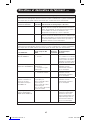
Guidance and Manufacturer’s Declaration
Product Information
AC Input Voltage 120V
Input Amp(s) 16A
No.ofPhases Single
Class Type Class 1
Plug/Connector Type IEC inlet C20
Operation Continuous
AC Input Frequency 60Hz
AC Input Protection (Qty./Type/Rating) Inputbreaker(2x20Athermal)
MaxACLeakageCurrent(uA) Less than 100uA
Weight 73.3lbs(33.2kg)
Contraindication None
Guidance and Manufacturer’s Declaration—Electromagnetic Emissions
This Medical-Grade UPS is intended for use in the electromagnetic environment specified below. The
customer or the user of this Medical-Grade UPS should assure that it is used in such an environment.
Emissions Test Compliance Electromagnetic Environment - Guidance
RF Emissions CISPR 11 Group 1 The Medical-Grade UPS uses RF energy only for its internal
function. Therefore, its RF emissions are very low and unlikely
to cause any interference in nearby electronic equipment.
RF Emissions CISPR 11 ClassB The Medical-Grade UPS is suitable for use in all
establishments other than domestic and those directly
connected to the public low-voltage power supply network
that supplies buildings used for domestic purposes.
12-10-307-93-3181.indb 10 11/2/2012 9:27:49 AM

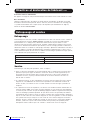
11
Guidance and Manufacturer’s Declaration cont.
Guidance and Manufacturer’s Declaration—Electromagnetic Immunity
This Medical-Grade UPS is intended for use in the electromagnetic environment specified below. The
customer or the user of this Medical-Grade UPS should assure that it is used in such an environment.
Immunity Test IEC 60601 Test Level
Compliance
Level
Electromagnetic
Environment - Guidance
Electrostatic Discharge (ESD)
IEC 61000-4-2
+ / - 6kV contact
+ / - 8kV air
Complies Floors should be wood,
concrete or ceramic tile. If
colors are covered with
synthetic material, the
relative humidity should be
atleast30%.
ElectricalFastTransient/Burst
IEC61000-4-3
+ / - 2kV for power supply
lines
+ / - 1kV for input/output
lines
Complies Mains power quality should
be that of a typical
commercial or hospital
environment.
Surge
IEC 61000-4-5
+ / - 1kV differential mode
+ / - 2kV common mode
Complies Mains power quality should
be that of a typical
commercial or hospital
environment.
Voltage dips, short
interruptions and voltage
variations on power supply
input lines
IEC 61000-4-11
<5%UT
(>95%dipinUT) for .5 cycle
40%UT
(60%dipinUT) for 5 cycles
70%UT
(30%dipinUT) for 25 cycles
<5%UT
(>95%dipinUT) for 5 seconds
Complies Mains power quality should
be that of a typical
commercial or hospital
environment.
PowerFrequency(50/60Hz)
Magnetic Field
IEC61000-4-B
3A/m Complies Power frequency magnetic
fields should be at levels
characteristic of a typical
location in a typical
commercial or hospital
environment.
Note:UT is the AC mains voltage prior to application of the test level.
Overcurrent Protection
The unit is equipped with 2 20A, branch-rated, circuit breakers.
Battery Pack
The unit comes with a 48VDC, rechargeable sealed lead-acid battery pack rated at 9 amp
hours.Yourbatteryshouldlastforseveralyears.Ifneeded,replacementbatterypacksforthis
UPSareavailablethroughTrippLite,modelnumberRBC48V-HGTWR.
12-10-307-93-3181.indb 11 11/2/2012 9:27:49 AM

12
Storage and Service
Storage
BeforestoringyourUPS,turnitcompletelyOFF:withtheUPSONandreceivingutilitypower,
pressandholdthe“ON/OFF/STANDBY”buttonforonesecond(analarmwillbeeponcebriefly
aftertheintervalhaspassed);then,unplugtheUPSfromthewalloutlet.IfyoustoreyourUPS
foranextendedperiodoftime,rechargetheUPSbatteriesonceeverythreemonths:plugthe
UPSintoawalloutlet;allowittochargefor12hours;andthenunplugitandplaceitbackin
storage.Note:afteryouplugtheUPSin,itwillautomaticallybeginchargingitsbatteries;
however, it will not supply power to its outlets (see Quick Installation section). If you leave your
UPSbatteriesdischargedforanextendedperiodoftime,theywillsufferapermanentlossof
capacity.
Permissible Storage and Transportation Conditions
Humidity 0-95%Non-Condensing
Temperature -15°Cto45°C;5°Fto113°F
Elevation 0 to 50,000 ft.
Service
BeforereturningyourUPSforservice,followthesesteps:
1. Review the installation and operation instructions in this manual to ensure that the service
problem does not originate from a misreading of the instructions. Also, check that the UPS
System's circuit breaker(s) are not tripped. This is the most common cause of service
inquiries which can be easily remedied by following the resetting instructions in this manual.
2. If the problem continues, do not contact or return the UPS to the dealer. Instead, call
TrippLiteat(773)869-1233.AservicetechnicianwillaskfortheUPS'smodelnumber,
serial number and purchase date and will attempt to correct the problem over the phone.
3.Iftheproblemrequiresservice,thetechnicianwillissueyouaReturnedMaterial
Authorization (RMA) number, which is required for service. If you require packaging, the
technician can arrange to send you proper packaging. Securely pack the UPS to avoid
damage during shipping. Do not use Styrofoam beads for packaging. Any damages (direct,
indirect, special, incidental or consequential) to the UPS incurred during shipment to Tripp
Lite or an authorized Tripp Lite service center is not covered under warranty. UPS Systems
shipped to Tripp Lite or an authorized Tripp Lite service center must have transportation
charges prepaid. Mark the RMA number on the outside of the package. If the UPS System is
within the 2-year warranty period, enclose a copy of your sales receipt. Return the UPS for
service using an insured carrier to the address given to you by the Tripp Lite service
technician.
Battery Replacement Door: Under normal conditions, the original battery in your UPS will last
severalyears.Batteryreplacementshouldbeperformedonlybyqualifiedservicepersonnel.
Referto“BatteryWarnings”intheSafetysection.ShouldyourUPSrequirebattery
replacement,visitTrippLiteontheWebatwww.tripplite.com/support/battery/index.cfmtolocate
the specific replacement battery for your UPS.
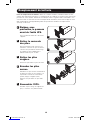
Battery Replacement
1 Carefully pull the
front panel away from
the UPS.
Place front panel on top of the unit. 1
12-10-307-93-3181.indb 12 11/2/2012 9:27:50 AM

13
Warranty Registration
Visit www.tripplite.com/warranty today to register the warranty for your new Tripp Lite product.
You'llbeautomaticallyenteredintoadrawingforachancetowinaFREETrippLiteproduct!*
*Nopurchasenecessary.Voidwhereprohibited.Somerestrictionsapply.Seewebsitefordetails.
FCC RADIO/TV INTERFERENCE NOTICE: (FOR CLASS A MODELS)
Note:ThisequipmenthasbeentestedandfoundtocomplywiththelimitsforaClassAdigitaldevice,pursuanttoPart15ofthe
FCC Rules. These limits are designed to provide reasonable protection against harmful interference when operated in a commercial
environment. This equipment generates, uses and can radiate radio frequency energy, and if not installed and used in accordance
withtheinstructionmanual,maycauseinterferencetoradiocommunications.Operationofthisequipmentislikelytocauseharmful
interferenceinwhichcasetheuserwillberequiredtocorrecttheinterferenceathisownexpense.Theusermustuseshieldedcables
andconnectorswiththisproduct.Anychangesormodificationstothisproductnotexpresslyapprovedbythepartyresponsiblefor
compliance could void the user's authority to operate the equipment.
Regulatory Compliance Identification Numbers
For the purpose of regulatory compliance certifications and identification, your Tripp Lite product has been assigned a unique
series number. The series number can be found on the product nameplate label, along with all required approval markings and
information. When requesting compliance information for this product, always refer to the series number. The series number
should not be confused with the marking name or model number of the product.
Tripp Lite has a policy of continuous improvement. Product specifications are subject to change without notice.
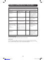
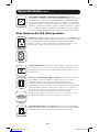
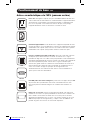
Note on Labeling
Two symbols are used on the label.
V~ : AC Voltage V : DC Voltage
Battery Replacement continued
2 Remove battery cover.
Use a screwdriver to remove the screws
holding the battery cover to the unit and
carefully remove the cover. Remove the
battery support bar. Disconnect the
wiring harness connecting the batteries
to the unit.
3 Remove old batteries.
Carefully pull the batteries from the
UPS.
4 Connect new batteries.
Connectthenewbatteriesinexactlythe
same manner as the old ones: positive
(red) connectors together and negative
(black) connectors together. Carefully
push batteries back into the UPS.
5 Reassemble UPS.
Reinstall the battery support bar, battery
cover and front panel.
2
3
4-5
12-10-307-93-3181.indb 13 11/2/2012 9:27:53 AM

14
Manual del propietario
1111 W. 35th Street, Chicago, IL 60609 USA • www.tripplite.com/support
Copyright © 2012 Tripp Lite. Todos los derechos reservados.
SmartPro® es una marca comercial registrada de Tripp Lite.
SMART2500XLHG
(AG-8589)
Sistema UPS Inteligente, Interactivo de Grado Médico
Aislamiento Total: Fuga inferior a 100µA
Instrucciones de seguridad importantes 15
Instalación rápida 16
Contenido del Empaque 16
Instalación opcional 17
Interfaz de Usuario 18
Instalación opcional 18
Operación básica 20
Orientación y Declaración del Fabricante 23
Almacenamiento y servicio 25
Reemplazo de batería 26
English 1
Français 27
12-10-307-93-3181.indb 14 11/2/2012 9:27:58 AM

15
Instrucciones de seguridad importantes
Declaración de Uso Indicado
Los Sistemas UPS de Grado Médico de Tripp Lite están diseñados para soportar y proteger equipo
de computación no médico, y dispositivos médicos que requieran reducción de fuga de corriente,
protección contra sobretensiones, regulación de voltaje, filtrado de ruido en la línea y respaldo por
batería durante interrupción en el servicio eléctrico y prueba del generador, ambos dentro y fuera
de áreas de atención a pacientes. Los Sistemas UPS de Grado Médico de Tripp Lite vienen con
clavijas y tomacorrientes de grado hospital que reducen la fuga a menos de 100µA.
GUARDE ESTAS INSTRUCCIONES
Este manual contiene importantes instrucciones que deben seguirse durante la instalación,
operación y el almacenamiento de todos los UPS de Tripp Lite. La no observancia de estas
advertencias anulará su garantía.
Nota: Su sistema UPS contiene fusibles sólo en el conductor de fase sin conexión a tierra. Los sistemas UPS
certificados por UL 60601-1 (véase Especificaciones) no se deben utilizar fuera de Estados Unidos y Canadá
y sólo se deben emplear en instalaciones de atención de salud, en sistemas con conexión a tierra donde las
condiciones de mantenimiento y supervisión garanticen que sólo personas calificadas reparen el sistema de
distribución eléctrica.
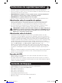
Advertencias sobre la ubicación del UPS
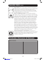
• Símbolosimportantes
Significa que debe revisarse la información en el manual antes de usarlo.
Se usa para indicar como advertencia que un párrafo es particularmente importante y
puede representar un riesgo a la seguridad.
Indica que las instrucciones deben observarse para un uso adecuado.
Advierte que los usuarios no se deben sentar o parar en la unidad.
Indica que no debe empujar la unidad.
• Nouseesteequipoenatmósferasenriquecidasconoxígenooadistanciasinferioresa0.3m
(1pie)deunpuntoenqueseventiledeliberadamenteunaatmósferaenriquecidaconoxígeno.
•TengacuidadoallevantarelUPS.DebidoalgranpesodelosUPSparamontaje,serequieren
por lo menos dos personas para que le ayuden a levantarlos e instalarlos.
•InstalesuUPSbajotecho,lejosdelahumedad,elcalor,elpolvoolaluzsolardirecta.
• Paramejordesempeño,elUPSdebeusarseenunaubicaciónquecumplaconlassiguientes
especificaciones:Temperatura:0a40°C(32a104°F);Humedad:0a95%(sin
condensación);Elevación:<2000m(6562pies)sobreelniveldelmar;Presión:<95kPA
•DejeunacantidadadecuadadeespacioalrededordetodoslosladosdelUPSparasua
adecuadaventilación.Noobstruyasusrespiraderosnilasaberturasdeventilación.
Advertencias sobre la conexión del UPS
•ElUPScontienesupropiafuentedeenergía(batería)Losterminalesdesalidapuedenestar
con energía incluso cuando el UPS no está conectado a un suministro de corriente alterna.
•ConectesuUPSaunatomadeCApuestaatierraapropiadamente.Nomodifiqueel
enchufedelUPSenningunaformaqueeliminesuconexiónatierra.Nouseadaptadores
queeliminenlaconexióndelUPSatierra.
•NoconecteelUPSasimismoyaquepodríadañarseyanularlagarantía.
•SivaaconectarsuUPSaungeneradordecorrientealternaaccionadoporunmotor,
el generador debe suministrar una salida filtrada, con regulación por frecuencia grado
computadora.LaconexióndesuUPSaungeneradoranularásuseguroUltimatedeporvida.
12-10-307-93-3181.indb 15 11/2/2012 9:27:58 AM

16
•ParaaislarelUPSdelaalimentaciónprincipal,desconectelaclavijadealimentación.
• Unavezconectado,nolimiteelaccesoalaclavijadeentrada.Laclavijadebeestaraccesible
parausarlacomomediodedesconexión.
• PRECAUCIÓN: Para garantizar la correcta conexión a tierra, el cable de alimentación
debe permanecer conectado todo el tiempo al suministro principal.
• ADVERTENCIA: No se permite modificación de este equipo.
•ElUPSnorequieremantenimiento.Notienepartesalasqueelusuariopuedadarservicio.
Advertencias sobre la conexión de equipos
•NoutilicesistemasUPSdeTrippLiteparaaplicacionesdesoportedevidaenlasqueun
funcionamiento defectuoso o una falla del UPS pudiera causar un mal funcionamiento o
una alteración importante en el funcionamiento de un dispositivo de soporte de vida.
•NoconectesupresoresdesobretensionesnicordonesdeextensiónalasalidadesuUPS.
Esto puede sobrecargarlo y anular su garantía y la del supresor de sobretensiones.
PRECAUCIÓN: La unidad es para interconexión exclusiva con equipo certificado por
IEC6060-1 en el entorno del paciente y equipo certificado por IEC 60950 fuera del
entorno del paciente. No haga contacto con SIP/SOP (como el puerto USB, puerto
RS232, etc.) y el paciente al mismo tiempo.
Advertencias sobre la batería
•Lasbateríaspresentanunpeligrodechoqueeléctricoyquemadurasdebidoalasaltas
corrientesdecortocircuito.Observelasprecaucionesapropiadas.Nodesechelasbateríasen
unincinerador.NoabraelUPSnilasbaterías.Nopongalosterminalesdelabateríaencortoo
en puente con ningún objeto. Apague y desconecte el UPS antes de reemplazar la batería. El
reemplazo de baterías debe ser realizado solamente por personal de servicio autorizado usando
el mismo número y tipo de baterías (plomo-ácido, selladas). Las baterías son reciclables.
Consultelareglamentaciónlocalparalosrequisitosdedisposicióndedesechos;enlosEE.UU.
llameal1-800-SAV-LEADoal1-800-8-BATTERY(1-800-8-228-8379)ovisite
www.rbrc.com para obtener información sobre el proceso de reciclaje. Tripp Lite ofrece una
líneacompletadecartuchosdereemplazodebateríaparaUPS(R.B.C.)Visitelapáginaweb
de Tripp Lite en www.tripplite.com para localizar la batería de reemplazo específica para su
UPS.
•Duranteelreemplazodebateríasenoperación(hot-swap),elUPSnoproporcionaráenergíade
respaldo en el caso de una falla del servicio eléctrico u otras interrupciones de energía.
•NoopereelUPSsinbaterías.
Desecho del UPS
• Cumplasiempreconlosreglamentoslocalesparalosmétodosadecuadosderecicladoy
desecho de equipo electrónico.
• AlcomprarunUPSnuevodeTrippLite,ustedpuedeenviarunUPSviejoparaserrecicladoen
una base de uno por uno y similar por similar. El equipo nuevo debe enviarse también a Tripp Lite
cuando se convierta en desperdicio.
Instrucciones de seguridad importantes
Contenido del Empaque
• SMART2500XLHGSistemaUPSInteligente,InteractivodeGradoMédico
• CabledealimentacióndeCA(C19aNEMA5-20P)
• CableDB9de1.83m[6pies]
• CableUSBde1.83m[6pies]
• CableRJ11de1.83m[6pies]
• TornilloMariposaparaConexiónaTierra
• SoportedeSujeciónyTornilloparaelCabledeAlimentación
• Manualdelusuario
12-10-307-93-3181.indb 16 11/2/2012 9:27:58 AM

17
Instalación rápida
1 Enchufe el UPS en un
tomacorriente en un
circuito dedicado.
ElSMART2500XLHGtieneuna
alimentación IEC C20 a la que debe
conectarse el cable icluido (C19 a
5-20P).
Acople el cable de alimentación incluido
al UPS insertando el conector IEC A del
cable de alimentación en la entrada de
energía IEC B localizada en la parte
posterior del UPS. Use el soporte incluido
C paraasegurarlaconexióndelcablede
alimentación.
Sistemas UPS listados en UL60601-1
solamente cumplen el estándar UL
60601-1 para equipo médico cuando se
enchufan en un tomacorriente de grado
médicoNEC517aprobadoeinstalado.
Nota: Después de conectar el UPS en un
tomacorriente activo de CA, el UPS (en modo
de espera) cargará automáticamente sus
baterías,* pero no suministrará energía a sus
tomacorrientes hasta que se encienda (ver
paso 3 a continuación).
* El LED “BATTERY CHARGE” [Carga de
Batería] será el único LED iluminado.
2 Conecte sus equipos
en el UPS.*
* Su UPS sólo está diseñado para dar soporte
a equipos electrónicos. Si la capacidad total
en VA para todos los equipos conectados a
las salidas protegidas por baterías de reserva /
protegidas contra sobretensión excede la
capacidad de salida del UPS, éste se
sobrecargará Para averiguar la capacidad de
sus equipos en VA, revise sus placas. Si la
capacidad del equipo está indicada en
amperios, multiplique los amperios por 120
para determinar los VA. (Ejemplo: 1 amperio
× 120 = 120 VA) Si no está seguro de si ha
sobrecargado las salidas del UPS, consulte la
descripción del LED “OUTPUT LOAD LEVEL”
(NIVEL DE CARGA DE SALIDA)
3 Encienda el UPS.
Presione y mantenga presionado el botón
“ON/OFF/STANDBY”(Encendido/Apagado/
Reserva) durante un segundo. La alarma
emitirá un pitido brevemente después de
pasado un segundo. Suelte el botón.
1
2
3
12-10-307-93-3181.indb 17 11/2/2012 9:27:59 AM

18
Interfaz de Usuario
A BotóndeOn/Off/Standby
B LEDsdeNiveldeCargadeSalida
C LED de Encendido
D LED de Corrección de Voltaje
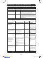
Nivel de Carga Estados Indicador de LED Alarma Sonora
0-75% Línea, Inversor Verde —
76-100% Línea, Inversor Amarillo —
101-110% Línea, Inversor Rojo Destellante —
>110% Línea Rojo —
>110% Inversor Rojo Encendido
Condición de Autonomia Estados Indicador LED Alarma Sonora
>3minremanentes Inversor Verde —
3-2minremanentes Inversor Amarillo —
<2 min remanentes Inversor Rojo Encendido
E LEDsdeAdvertenciadeBatería
F LEDsdeCargadeBatería
G BotónMute/Test
A B C D E F G
Instalación opcional
Estas conexiones son opcionales. Su UPS funcionará correctamente sin ellas.
1 Comunicaciones USB y
serie RS-232
UseelcableUSBincluido(vea1a) y/o el
cableserieDB9(vea1b) para conectar el
puerto de comunicaciones de su
computadora al puerto de
comunicaciones de su UPS. Instale en su
computadora el software PowerAlert de
Tripp Lite apropiado para su sistema
operativo.
1a
1b
12-10-307-93-3181.indb 18 11/2/2012 9:28:02 AM

19
Instalación opcional continúa
2 Conexión de puerto
EPO
Esta característica opcional es sólo para
aquellas aplicaciones que requieran una
conexiónalcircuitodedesconexiónde
emergencia(EPO)delainstalación
Cuando el UPS está conectado a este
circuito, permite el apagado de
emergencia del inversor del UPS.
Usando el cable suministrado, conecte el
puertoEPOdesuUPS(vea2a) a un
contacto normalmente cerrado o
normalmente abierto suministrado por el
usuario, de acuerdo con el diagrama del
circuito (vea 2b).ElpuertoEPOnoesun
supresor de sobretensiones de línea
telefónica;noconecteunalínea
telefónica en este puerto.
3 Conexión de la Batería
Externa
ElSMART2500XLHGestáequipadocon
capacidadparaunabateríaexternapara
aplicaciones que requieran un tiempo de
autonomíaextendido.Laparteposterior
de la unidad incluye el conector para el
módulodebateríasexternasyun
interruptor de la tasa del cargador. Para
acceder al conector, debe retirarse la
cubierta instalada en fábrica.
El interruptor de la tasa del cargador está
configurado de forma predeterminada a la
configuracióndebateríainterna(INT.
BATT).Alusarunmódulodebaterías
externas,elinterruptornecesitacolocarse
enlaconfiguracióndebateríaexterna
(EXT.BATT).Laconexióndeunmódulo
de baterías y configuración del interruptor
pueden hacerse mientras la unidad está
en funcionamiento.
Nota: dejar el interruptor de la tasa de
cargador en INT. BATT mientras se conecta a
una batería externa no dañará la unidad. De
cualquier modo, aumentará el tiempo
necesario para recargar las baterías después
de un evento de energía.
2a
4-5
2b
3
Cubierta
del
Conector
de la
Batería
Externa
Interruptor
de la
Tasa del
Cargador
12-10-307-93-3181.indb 19 11/2/2012 9:28:05 AM

20
Botones (Panel frontal)
Operación básica
Botón "ON/OFF/STANDBY" (Encendido/Apagado/Reserva)
• Para encender el UPS: Con el UPS conectado en una toma de CA con
energía*,presioneymantengapresionadoelbotón“ON/OFF/STANDBY”
(Encendido/Apagado/Reserva) por un segundo.** Suelte el botón. Si no hay
energíadelared,puede“arrancarenfrío”elUPS(esdecir,encenderloy
suministrar energía de sus baterías por un tiempo limitado***) presionando
ymanteniendopresionadoelbotón“ON/OFF/STANDBY”(Encendido/
Apagado/Reserva) durante un segundo.**
• Para apagar el UPS: Con el UPS encendido y recibiendo energía de la red,
presioneymantengapresionadoelbotón“ON/OFF/STANDBY”(Encendido/
Apagado/Reserva) durante un segundo.** Luego desconecte el UPS de la
toma de corriente. El UPS se apagará.
* Después de conectar el UPS en una toma de CA con energía, el equipo (en modo
"Standby") cargará automáticamente sus baterías, pero no suministrará energía a
sus salidas hasta que sea encendido.
** La alarma emitirá un pitido brevemente después de pasado el intervalo indicado.
*** Si está completamente cargada.
Botón "MUTE/TEST" (SILENCIO/PRUEBA)
Para silenciar las alarmas UPS: Presione brevemente el botón MUTE/TEST
(SILENCIO/PRUEBA)yluegosuéltelo.
Nota: Para desarmar de manera permanente las alarmas audibles del UPS:
Comuníquese con Soporte Técnico de Tripp Lite para instrucciones.
Para ejecutar una auto-prueba: Con su UPS conectado y encendido,
presione y mantenga presionado el botón MUTE/TEST (Silencio/Prueba). Siga
presionando el botón hasta que la alarma suene varias veces y el UPS realice
unaauto-prueba.Vea“Resultadosdeunaauto-prueba”másabajo.
Nota: Puede dejar equipos conectados durante una auto-prueba. Sin embargo, el
UPS, no realizará una auto-prueba si no está encendido (vea la descripción del Botón
"ON/OFF/STANDBY").
¡PRECAUCIÓN! No desconecte su UPS para probar sus baterías. Esto
eliminaría la conexión de seguridad a tierra y podría introducir una
sobretensión dañina en sus conexiones de red.
Resultados de una auto-prueba: La prueba durará cerca de 10 segundos
mientras el UPS conmuta a batería para probar su capacidad de carga y la
recarga de la batería.
•SielLED“OUTPUTLOADLEVEL”(NIVELDECARGADESALIDA)
permanece encendido rojo y la alarma continúa sonando después de la
prueba, las salidas del UPS están sobrecargadas. Para eliminar la
sobrecarga, desconecte algo de su equipo y ejecute la auto-prueba
repetidamente hasta que el LED ya no esté encendido rojo y la alarma ya
no esté sonando.
¡PRECAUCIÓN! Cualquier sobrecarga que no sea corregida por el
usuario inmediatamente después de una auto-prueba puede causar que
el UPS se apague y deje de suministrar energía de salida en el caso de
una falla del servicio eléctrico o una baja de voltaje.
•SielLED“BATTERYWARNING”(ADVERTENCIADEBATERÍA)sigue
encendido y la alarma continúa sonando después de la prueba, las baterías
del UPS deben recargarse o reemplazarse. Permita que el UPS se recargue
continuamente por 12 horas y repita la auto-prueba. Si el LED permanece
encendido, contacte con Tripp Lite para obtener servicio. Si su UPS requiere
el reemplazo de su batería, visite www.tripplite.com para localizar la batería
de reemplazo Tripp Lite específica para su UPS.
12-10-307-93-3181.indb 20 11/2/2012 9:28:05 AM
La page est en cours de chargement...
La page est en cours de chargement...
La page est en cours de chargement...
La page est en cours de chargement...
La page est en cours de chargement...
La page est en cours de chargement...
La page est en cours de chargement...
La page est en cours de chargement...
La page est en cours de chargement...
La page est en cours de chargement...
La page est en cours de chargement...
La page est en cours de chargement...
La page est en cours de chargement...
La page est en cours de chargement...
La page est en cours de chargement...
La page est en cours de chargement...
La page est en cours de chargement...
La page est en cours de chargement...
La page est en cours de chargement...
La page est en cours de chargement...
-
 1
1
-
 2
2
-
 3
3
-
 4
4
-
 5
5
-
 6
6
-
 7
7
-
 8
8
-
 9
9
-
 10
10
-
 11
11
-
 12
12
-
 13
13
-
 14
14
-
 15
15
-
 16
16
-
 17
17
-
 18
18
-
 19
19
-
 20
20
-
 21
21
-
 22
22
-
 23
23
-
 24
24
-
 25
25
-
 26
26
-
 27
27
-
 28
28
-
 29
29
-
 30
30
-
 31
31
-
 32
32
-
 33
33
-
 34
34
-
 35
35
-
 36
36
-
 37
37
-
 38
38
-
 39
39
-
 40
40


Tripp Lite SmartPro, 1920W Manuel utilisateur
- Catégorie
- Alimentations sans interruption (UPS)
- Taper
- Manuel utilisateur
- Ce manuel convient également à
dans d''autres langues
Documents connexes
-
Tripp Lite SMART2500XLHG Le manuel du propriétaire
-
-
-
Tripp Lite AG-0006 Le manuel du propriétaire
-
Tripp Lite SMX & OMNIX UPS Systems Le manuel du propriétaire
-
-
-
-