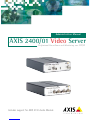
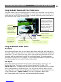
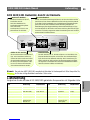
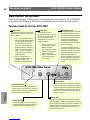
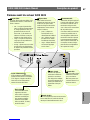
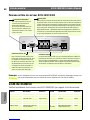
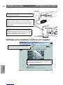
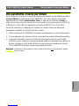
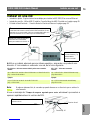
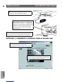
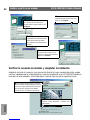
Axis 2401 Manuel utilisateur

Catégorie
Serveurs / encodeurs vidéo
Taper
Manuel utilisateur

Ce manuel convient également à

AXIS 2400/01 Video Server
Professional Surveillance and Monitoring over TCP/IP
Administration Manual
Includes support for AXIS 2191 Audio Module
AXIS COMMUNICATIONS
<Product Name> Quick User’s Guide
AXIS 2400/2401 Admin Manual
2
About This Document
This manual is intended for both administrators and users
of the AXIS 2400/2401 Video Server, and is applicable for
software release 2.31. It includes simple step-by-step
instructions for configuring, managing and using the
AXIS 2400/2401 Video Server on your network.
Previous experience of networking will be of use to the
reader when installing and using this product. Some
knowledge of UNIX or Linux-based systems would also be
beneficial, for developing custom PHP-based
programming scripts and applications.
Readers should use this document as a supplement to the
Wizards and other on-line information available via the
Web-based interface. Later versions of this document will
be posted to the Axis Website, as required.
Safety Notices
Please observe all safety markings when using this
product.
Caution! - Potential hazard that can damage the product.
Important! - Potential hazard that can seriously impair
operation.
Do not proceed beyond any of the above notices until you
have fully understood the implications.
Legal Considerations
Camera surveillance can be prohibited by laws that vary
from country to country. Check the laws in your local
region before using the AXIS 2400/2401 for surveillance.
Electromagnetic Compatibility (EMC)
USA - This equipment generates, uses, and can radiate
radio frequency energy and if not installed and used in
accordance with the instruction manual, may cause
interference to radio communications. It has been tested
and found to comply with the limits for a Class A
computing device pursuant to Subpart B of Part 15 of FCC
rules, which are designed to provide reasonable protection
against such interference when operated in a commercial
environment. Operation of this equipment in a residential
area is likely to cause interference, in which case the user
at his/her own expense will be required to take whatever
measures may be required to correct the interference.
Shielded cables should be used with this unit to ensure
compliance with the Class A limits.
Europe - This digital equipment fulfills the
requirements for radiated emission according to limit B of
EN55022/1994, and the requirements for immunity
according to EN50082-1/1992 residential, commercial,
and light industry.
Liability
Every care has been taken in the preparation of this manual;
if you detect any inaccuracies or omissions, please inform
your local Axis office. Axis Communications AB cannot be
held responsible for any technical or typographical errors and
reserves the right to make changes to the product and
manuals without prior notice. Axis Communications AB
makes no warranty of any kind with regard to the material
contained within this document, including, but not limited to,
the implied warranties of merchantability and fitness for a
particular purpose. Axis Communications AB shall not be
liable nor responsible for incidental or consequential damages
in connection with the furnishing, performance or use of this
material.
Trademark Acknowledgments
Acrobat, Adobe, Boa, Ethernet, IBM, Internet Explorer, LAN
Manager, Linux, Macintosh, Microsoft, Netscape Navigator,
OS/2, UNIX, Windows, WWW are registered trademarks of the
respective holders. Java and all Java-based trademarks and
logos are trademarks or registered trademarks of Sun
Microsystems, Inc. in the United States and other countries.
Axis Communications AB is independent of Sun
Microsystems Inc.
Support Services
Should you require any technical assistance, please contact
your Axis reseller. If your questions cannot be answered
immediately, your reseller will forward your queries through
the appropriate channels to ensure a rapid response. If you are
connected to the Internet, you can:
download user documentation and firmware updates
find answers to resolved problems in the FAQ database.
Search by product, category, or phrases
report problems to Axis support staff by logging in to
your private support area
visit the Axis Support Web at www.axis.com/techsup/
AXIS 2400/2401 Administration Manual
Revision 2.11
Part No: 19097
Dated: April 2002
Copyright © Axis Communications AB,
1996 - 2002
AXIS 2400/2401 Admin Manual 3
Table Of Contents
Product Description. . . . . . . . . . . . . . . . . . . . . . . . . . . . . . . . . . . . . . . . . . . . . . . . 6
AXIS 2400 Front Panel ..................................................6
AXIS 2401 Front Panel ..................................................7
AXIS 2400/2401 Rear Panel ..............................................8
Hardware Inventory . . . . . . . . . . . . . . . . . . . . . . . . . . . . . . . . . . . . . . . . . . . . . . . 8
Installing on a Network. . . . . . . . . . . . . . . . . . . . . . . . . . . . . . . . . . . . . . . . . . . . . 9
Verifying and Completing the Installation From Your Browser ..................10
Installing via the Null Modem Cable . . . . . . . . . . . . . . . . . . . . . . . . . . . . . . . . . . 11
Step A - Connecting Your Computer Using the Null Modem Cable ...............11
Step B - Creating a Dial-Up Networking Connection ..........................12
Verifying the Modem Connection and Completing the Installation ...............13
Configuring the Video Server . . . . . . . . . . . . . . . . . . . . . . . . . . . . . . . . . . . . . . . 14
The Administration Tools ...............................................14
Designing your Application .............................................17
General Server Settings ................................................18
Network Settings ....................................................20
Dynamic IP Address Notification Settings ..................................21
Video Settings .......................................................22
Serial Port Settings ...................................................24
Pan Tilt Settings .....................................................26
Modem Settings .....................................................26
Reinstating the Factory Default Settings ...................................27
Using the Video Server . . . . . . . . . . . . . . . . . . . . . . . . . . . . . . . . . . . . . . . . . . . . 28
Accessing your Surveillance Images .......................................28
Positional Control of the Video Sources ....................................30
The AXIS 2191 Audio Module . . . . . . . . . . . . . . . . . . . . . . . . . . . . . . . . . . . . . . . 31
Installing the Audio Module ............................................33
Configuring the Audio Module ..........................................34
Using the Audio Module with Your Video Server .............................35
Appendix A - Other IP Setup Methods. . . . . . . . . . . . . . . . . . . . . . . . . . . . . . . . . 38
Notes for Macintosh Users .............................................38
Using the AXIS IP Installer ..............................................39
Appendix B - Troubleshooting. . . . . . . . . . . . . . . . . . . . . . . . . . . . . . . . . . . . . . . 40
AXIS 2400/2401 Admin Manual
4
PINGing Your IP Address ...............................................41
Appendix C - Updating the Firmware. . . . . . . . . . . . . . . . . . . . . . . . . . . . . . . . . . 44
Obtaining Updated firmware ............................................44
Updating the firmware .................................................44
Appendix D - Customizing The Video Server . . . . . . . . . . . . . . . . . . . . . . . . . . . . 45
Modifying the File System ..............................................45
Configuring using FTP .................................................45
Custom Web Pages ...................................................46
Appendix E - Technical Specifications . . . . . . . . . . . . . . . . . . . . . . . . . . . . . . . . . 49
Appendix F - The RS-232 Interface . . . . . . . . . . . . . . . . . . . . . . . . . . . . . . . . . . . 51
Physical Connector ...................................................51
Connecting Pan/Tilt Devices .............................................52
Appendix G - The I/O Terminal Block. . . . . . . . . . . . . . . . . . . . . . . . . . . . . . . . . . 53
Controlling and Monitoring .............................................55
Produktbeschreibung und Installationsanleitung
Produktbeschreibung . . . . . . . . . . . . . . . . . . . . . . . . . . . . . . . . . . . . . . . . . . . . . . 57
AXIS 2400 Bedienfeld, Ansicht von vorne ..................................57
AXIS 2401 Bedienfeld, Ansicht von vorne ..................................58
AXIS 2400/2401 Bedienfeld, Ansicht der Rückseite ...........................59
Lieferumfang . . . . . . . . . . . . . . . . . . . . . . . . . . . . . . . . . . . . . . . . . . . . . . . . . . . . 59
Installation im Netzwerk . . . . . . . . . . . . . . . . . . . . . . . . . . . . . . . . . . . . . . . . . . . 60
Überprüfen und Abschließen der Installation von Ihrem Browser aus .............61
Installation über Modem. . . . . . . . . . . . . . . . . . . . . . . . . . . . . . . . . . . . . . . . . . . . 62
Schritt A - Anschließen Ihres Computers über das Null-Modemkabel .............62
Schritt B - Erstellen einer DFÜ-Netzwerkverbindung ..........................63
Überprüfen der Modemverbindung und Abschliesen der Installation ..............64
Werkseitige Standardeinstellungen. . . . . . . . . . . . . . . . . . . . . . . . . . . . . . . . . . . . 65
Decsription du Produit et Guide d’Installation
Description du produit . . . . . . . . . . . . . . . . . . . . . . . . . . . . . . . . . . . . . . . . . . . . . 66
Panneau avant du serveur AXIS 2400 .....................................66
Panneau avant du serveur AXIS 2401 .....................................67
AXIS 2400/2401 Admin Manual 5
Panneau arrière du serveur AXIS 2400/2401 ................................68
Liste du matériel . . . . . . . . . . . . . . . . . . . . . . . . . . . . . . . . . . . . . . . . . . . . . . . . . 68
Installation sur un réseau . . . . . . . . . . . . . . . . . . . . . . . . . . . . . . . . . . . . . . . . . . 69
Vérification et fin d’installation à partir de votre navigateur ....................70
Installation à l’aide d’un modem . . . . . . . . . . . . . . . . . . . . . . . . . . . . . . . . . . . . . 72
Etape A - Connexion à l’aide du câble "Null Modem" .........................72
Etape B - Création d’une connexion d’accès réseau à distance ..................73
Vérification et fin d’installation de la connexion modem .......................74
Des paramètres d’usine par défaut. . . . . . . . . . . . . . . . . . . . . . . . . . . . . . . . . . . . 75
Descripción del producto y Guía de instalación
Descripción del producto . . . . . . . . . . . . . . . . . . . . . . . . . . . . . . . . . . . . . . . . . . . 76
AXIS 2400 Panel frontal ...............................................76
AXIS 2401 Panel frontal ...............................................77
AXIS 2400/2401 Panel posterior .........................................78
Inventario de hardware . . . . . . . . . . . . . . . . . . . . . . . . . . . . . . . . . . . . . . . . . . . . 78
Instalar en una red . . . . . . . . . . . . . . . . . . . . . . . . . . . . . . . . . . . . . . . . . . . . . . . 79
Verificando y completando la instalación desde su buscador web ...............80
Instalar a partir de un módem. . . . . . . . . . . . . . . . . . . . . . . . . . . . . . . . . . . . . . . 82
Paso A - Conectar su ordenador usando el Cable de módem nulo ................82
Paso B - Crear un acceso telefónico a redes ................................83
Verificar la conexión de módem y completar la instalación .....................84
Incluir los parámetros por defecto . . . . . . . . . . . . . . . . . . . . . . . . . . . . . . . . . . . . 85
Index . . . . . . . . . . . . . . . . . . . . . . . . . . . . . . . . . . . . . . . . . . . . . . . . . . . . . . . . . 86
Product Description AXIS 2400/2401 Admin Manual
6
Product Description
Read the following information to familiarize yourself with the AXIS 2400/2401, making
particular note of where the connectors and indicators are located.
AXIS 2400 Front Panel
DIP Switches
A corresponding line termination
switch for each of the supported
video outputs. All units are
shipped with the line termination
enabled for each supported video
input; that is, with the DIP
switches set in the down-position.
If the AXIS 2400 is to be con-
nected in parallel with other
equipment, disable the input ter-
mination by turning the corre-
sponding DIP switch to the
up-position (OFF). Failure to do
this can cause the picture quality
to be impaired.
Serial Number
Located on the underside label of the AXIS
2400, the serial number is identical to the
Ethernet address of the unit.
Status Indicator
The multi-colored status indicator shows
the operational status of the server, as
described below:
green - the indicator flashes briefly
and momentarily displays orange
during the start-up and self-test
routines; the indicator then displays
green to indicate a healthy unit sta-
tus.
red - the indicator will display red
only if a problem with the AXIS
2400 has occurred
orange - flashes orange when reset-
ting the factory default settings.
Network Indicator
After completion of the startup
and self test routines, the
multi-colored Network Indicator
flashes independently, as fol-
lows:
yellow - indicating net-
work activity on a 10Mbps
Ethernet network
green - indicating network
activity on a 100Mbps Fast
Ethernet network
red - indicating no physical
connection to the network.
Power Indicator
The Power indicator is normally lit while
power is applied. If it is not lit, or it
flashes, there is a problem with the AXIS
2400 external power source.
Control Button
This button is recessed within the product cas-
ing. Using a suitably pointed object, press this
button to restore the factory default settings,
as described in Network Settings, on page 20.
Video Inputs
Accommodates up to 4 separate video sources
(VIDEO 1- VIDEO 4) simultaneously.
Each supported video input is terminated using a
coax/BNC connector. Physical connections made
using RG59, 75 Ohm coax video cable; have a rec-
ommended maximum length of 800 feet (250
meters).
http://www.axis.com
AXIS 2400 Video Server
STATUS
NETWORK
POWER
VIDEO 1 VIDEO 2 VIDEO 3 VIDEO 4
75 ON
1 2 3 4
AXIS 2400/2401 Admin Manual Product Description 7
AXIS 2401 Front Panel
DIP Switch
A single line termination for the
supported video output. Units are
shipped with the line termination
enabled; that is, with the DIP
switch set in the down-position.
If the AXIS 2401 is to be con-
nected in parallel with other
equipment, disable the input ter-
mination by turning the corre-
sponding DIP switch to the
up-position (OFF). Failure to do so
can cause the picture quality to
be impaired.
Serial Number
Located on the underside label of the AXIS
2401, the serial number is identical to the
Ethernet address of the unit.
Status Indicator
The multi-colored status indicator
defines the operational status of the
server, as described below:
green - the indicator flashes briefly
and momentarily displays orange
during the start-up and self-test
routines; the indicator then displays
green to indicate a healthy unit sta-
tus.
red - the indicator will display red
only if a problem with the AXIS
2401 has occurred
orange - flashes orange when reset-
ting the factory default settings.
Network Indicator
After completion of the startup
and self test routines, the
multi-colored Network Indica-
tor flashes independently, as
follows:
yellow - indicating network
activity on a 10Mbps
Ethernet network
green - indicating network
activity on a 100Mbps Fast
Ethernet network
red - indicating no physical
connection to the network.
Power Indicator
The Power indicator is normally lit while
power is applied. If it is not lit, or it
flashes, there is a problem with the AXIS
2401 external power source.
Control Button
This button is recessed
within the product casing.
Using a suitably pointed
object, press this button to
restore the factory default
settings. For further infor-
mation, refer to Network
Settings, on page 20.
Video Input
Coaxial BNC connector support-
ing a single video source. The
physical connection is made using
RG59, 75 Ohm coax video cable;
with a recommended maximum
length of 800 feet (250 meters).
Video Output
A single video
loopthrough (VIDEO
OUT) connected in
parallel with VIDEO IN
and terminated with a
coax/BNC connector.
Allows direct connec-
tion of an external
monitor. Set dipswitch
to OFF when in use.
Hardware Inventory AXIS 2400/2401 Admin Manual
8
AXIS 2400/2401 Rear Panel
Note: The power supply for your AXIS 2400/2401 is country-specific. Please check that the type you
are using is correct. See below.
Hardware Inventory
Check the items supplied with your AXIS 2400/2401 against the following list:
Item Title/Variants Part Numbers Item Title/Variants Part Numbers
Video Server AXIS 2400 0092-001-02 Power Supply
(PS-D) Europe 14233
AXIS 2401 (NTSC) 0103-011-02 UK 14234
AXIS 2401 (PAL) 0103-001-02 Australia 14255
Null Modem Cable - 16954 USA 14253
Warranty Document 18640 Japan 14254
Disk Media AXIS Network
Camera CD v2.0 (or
later)
-This Docu-
ment AXIS 2400/2401
Administration
Manual v2.1
19097
Power Supply Connector
A single Jack socket (PS-D) for
connection of the AXIS 2400/2401
power supply. The terminal block
connector provides an auxiliary
connection point for AC or DC
power to the unit.
Network Connector
The AXIS 2400/2401 is designed for 10 Mbps Ethernet and
100 Mbps Fast Ethernet networks and connects to the net-
work via a standard RJ45 connector. Supporting NWAY,
the AXIS 2400/2401 detects the speed of the local net-
work segment and varies the speed of data communication
accordingly (between 10 Mbps and 100 Mbps).
I/O Terminal Block
The I/O Terminal Block connector is located between the two serial ports on the
rear panel and provides the physical interface to one relay switch output, four
digital photo-coupled inputs, and an RS-485 interface. Use this connector for
transmitting data over multi-drop communication lines, RS-485 Pan Tilt devices,
and external triggering - typically associated with CCTV equipment. The connector
can be utilized as an alternative connection point for DC supply to the unit.
RS-232 Serial Connectors
Two 9-pin D-sub connectors providing RS-232 serial con-
nection. Typically used for Pan/Tilt device interface. COM1
is multiplexed with the RS-485 port via the Terminal
Block Connector. COM2 can also be used for connecting a
modem or the AXIS 2191 Audio Module.
POWER
PS-D COM 1 COM 2 ETHERNET
10/100
1 2 3 4 5 6 7 8
9 10111213141516
AXIS 2400/2401 Admin Manual Installing on a Network 9
Installing on a Network
Quick installation - Follow the instructions below to quickly install on an Ethernet network.
Easy installation - See Using the AXIS IP Installer, on page 39.
Macintosh users - Please refer to Notes for Macintosh Users, on page 38.
Using an appropriate method for your operating system, assign your product with a unique IP
address from a computer on your network, as follows:
Note: In some Unix systems, the arp command can be located in a directory that is not on the
command path.
You will now see Request timed out... messages repeatedly returned in the window.
Note the Serial number on the
underside of the unit. You need to
know this to set the IP address.
Connect the video output of your camera(s) to the AXIS 2400/2401
video port(s) using standard 75 Ohm coaxial video cable, terminated
with a BNC-connector. (Use a BNC-to-RCA converter if your camera is
supplied with a standard phono-type (RCA) connector.)
Serial number same as
Ethernet number; e.g.
00408c100086 =
00-40-8c-10-00-86
Windows only - Start a DOS window and type these commands:
Syntax:
arp -s <Server IP address> <Ethernet address> <my PC IP address>
ping -t <Server IP address>
Example:
arp -s 172.21.1.200 00-40-8c-10-00-86 172.21.1.193
ping -t 172.21.1.200
UNIX only - Type this in your command line:
Syntax:
arp -s <IP address> <Ethernet address> temp
ping <IP address>
Example:
arp -s 172.21.1.200 00:40:8c:10:00:86 temp
ping 172.21.1.200
Connect an Ethernet cable to the AXIS
2400/2401 and attach it to the network.
Network connector
RJ-45 connector
Installing on a Network AXIS 2400/2401 Admin Manual
10
Verifying and Completing the Installation From Your Browser
Important!
Upon delivery, the AXIS 2400/01 is configured for open access (anonymous users). The unit is sup-
plied with one pre-configured Administrator username and password, set to root and pass, respec-
tively. The Administrator password must be changed immediately to prevent unauthorized access to
the Admin Tools and/or product images, as defined in the Security Settings.
To enable the updating of images in Microsoft Internet Explorer, set your browser to allow ActiveX
controls and perform a once-only installation of Axis' ActiveX component onto your workstation. If
your working environment restricts or prohibits the downloading of additional software components,
you can alternatively, from the Image Settings, configure your AXIS 2400/01to use a Java applet for
updating the images. Refer to the online Help for more information.
Exit ping. The installation is now complete, and you are ready to
access the AXIS 2400/2401 from your browser, as described in the
next section.
Power Supply
Connector
Connect the power supply to the unit and connect
it to your main power supply.
Approximately 10-15 seconds after connecting
the power supply, the message ‘Reply from
172.21.1.200...’ - or similar, is returned
within the window. Ensure that the Power Indica-
tor is permanently lit and that the Network Indi-
cator flashes intermittently.
Network Indicator
Power Indicator
Start your browser and enter the IP address of the
AXIS 2400/2401 in the location/address field.
Click the Installation Wizard. The wizard guides
you through the remaining installation procedures.
AXIS 2400/2401 Admin Manual Installing via the Null Modem Cable 11
Installing via the Null Modem Cable
This section describes how to install the AXIS 2400/01 using the null modem cable. For information
on how to configure the unit for modem operation, please see
Modem Settings,
on page 26.
Important!
Step A - Connecting Your Computer Using the Null Modem Cable
Although instructions for installing the AXIS 2400/2401 using a null modem cable are provided below, it is
recommended that, wherever possible, the unit is initially installed and configured over a network.
The information and examples featured here are specific to Windows 2000, but the process is similar in
other versions of Windows. Refer to your system information for further information on creating a Dial-Up
Networking connection if you are using any other operating system.
Windows Dial-Up Networking and TCP/IP must be correctly installed prior to commencing with the
modem cable connection. Detailed information on how to check this is provided in Windows Help.
Connect the supplied Null modem cable
between the COM-2 Serial Connector on
the AXIS 2400/01 and the COM-port on
your computer. Press the Power button
on the front panel and check that the
Power Indicator lights up.
From the Start menu, open the
Control Panel and click Phone and
Modem Options. Select Modems.
If a Standard Modem is already set up, you
should proceed directly to the next page. If no
modem is installed, click Add and go to step 5.
Select the Standard 28800
modem from the displayed list
of modems. Click Next>.
Check the box: Don’t detect my modem,
I will select it from a list. Click Next>.
A standard 28800 modem connection
is now available for the AXIS 2400/01.
Click Finish to complete the installation.
Select the serial port to which your
AXIS 2400/01 is now connected via the
Null Modem cable. Click Next>.
Installing via the Null Modem Cable AXIS 2400/2401 Admin Manual
12
Step B - Creating a Dial-Up Networking Connection
Follow the steps below to create a Dial-Up networking connection to the AXIS 2400/2401:
Click the Start button, Settings, Network
and Dial-up Connections, and finally, Make
New Connection. Click Next> when the
Wizard starts.
Set the type of connection as
Dial-up to Private Network. Click
Next.
Provide the connection with a
name (Axis in our example) and
then click Finish.
A telephone number is requested
in this dialog, but as it won’t actually
be used, simply enter any dummy
number. Click Next>.
AXIS 2400/2401 Admin Manual Installing via the Null Modem Cable 13
Verifying the Modem Connection and Completing the Installation
Having initiated your dial-up connection, as described above, you can quickly test it by
accessing the AXIS 2400/2401 from a browser (Netscape 4.x or Internet Explorer 4.x/5.x)
as follows:
After clicking Finish in the Network
Connection Wizard, the Dial-up dialog
opens. Click Properties.
Select the installed modem and
click Configure.
Finally, enter the default User
name Root and the password
pass. Click Dial.
Set the Maximum Speed to 115200
bps. Click OK twice to get back to the
dial-up dialog.
Since the AXIS 2400/2401 emulates a DNS
server, you can type in any URL (containing a
period) in the Location/Site field of your
browser, as shown here.
Click the Installation Wizard. The wizard guides
you through the remaining installation procedures.
my.2400
Configuring the Video Server AXIS 2400/2401 Admin Manual
14
Configuring the Video Server
After deciding on the application you wish to develop and having installed your AXIS
2400/2401, the unit is now either connected directly to a local area network, or connected
to a local PC using the supplied Null Modem Cable.
This section describes how to configure the AXIS 2400/2401 and is intended specifically
for product Administrators – who normally have high-level privileges denied to ordinary
users.
The AXIS 2400/2401 is configured from a standard browser (Netscape Navigator 4.x or
Microsoft Internet Explorer 4.x/5.x), by using the Administration Tools.
Important!
The Administration Tools
The Web-based Administration tools are displayed in an intuitive graphical user interface
that allows simple point-and-click system configuration. How to access and use the tools is
explained in the following pages.
Tip! On-line help is available on every page of the AXIS 2400/2401Web interface.
This information is of particular relevance when configuring the unit and should be used as a
first point of reference for resolving any administration queries. The help system is stored
internally in the unit.
Accessing the Tools
Follow the instructions below to access the Administration Tools from a browser:
1. Start the browser and enter the name or IP address of the AXIS 2400/2401 in the
location/address field.
Example!
2. The Application page is now displayed. Click the Admin button to display the
Administration Overview page and the Administration Tools.
To access the AXIS 2400/2401 configuration pages, you must first set the IP address, as described in
Installing on a Network, on page 9.
http://172.21.1.200/
AXIS 2400/2401 Admin Manual Configuring the Video Server 15
3. The various components of the video server are shown as icons on the page. Simply
click the desired component and configure it directly from here.
Important!
If this is the first time you have accessed the AXIS 2400/2401, the Welcome page will be now be dis-
played. Click the button for the Installation Wizard and configure your application.
To enable the updating of images in Microsoft Internet Explorer, set your browser to allow ActiveX
controls and perform a once-only installation of Axis' ActiveX component onto your workstation. If
your workstation restricts the downloading of additional software components, you can alternatively
configure your AXIS 2400/2401 to use a Java applet for updating the images.
Administrators can choose not to display the Administration and other navigational buttons from the
user interface. Selecting this feature ultimately means that the Administration tools can then only be
accessed by entering the full Admin address into the browser’s URL field; for example:
http://172.21.1.200/admin/.
Configuring the Video Server AXIS 2400/2401 Admin Manual
16
Admin Tools - Overview
The Administration Tools provide access to the following tools and parameters:
COM Port
Installation Wizard
Application Wizard
General
Network
Pan Tilt
Date and Time
Specify the system settings for the supported networking protocols, including:
TCP/IP (Network settings), DNS (Domain Name System Settings) and SMTP (E-Mail
Settings). Also provides access to the settings for Dynamic IP Address Notification
Set server parameters to factory default.
Define the user name and password
for administratrors and users.
Restart the AXIS 2400/2401.
These 4 buttons show various
product information.
Set the system date & time,
manually or automatically.
Sets all of the parameters required for securely viewing images directly in a browser;
including: TCP/IP (Network), SMTP (e-mail), Date/Time, and System Security settings.
Use the Application Wizard for developing the following applications:
transmitting images to a remote server on your network
sending e-mails with embedded images, or links to recorded video streams
developing alarm or time-based image applications
Define the type of modem you want to use
and specify the flow control, initialization
string and other settings. (COM2 only).
Video
(with or without
Set the image features; such as: display-
ing text, clock, color, Black & White etc.
Define the video transmission standard,
automatically or manually.
Create and recall Pan Tilt and Zoom pre-
set conditions (only visible if the video
source is connected to a pan tilt device).
Image
Input/Modulation
Video
Preset Positions
Choose your default viewer and personal settings.
Security
Layout
Modem Configure the connec-
tion to your ISP and edit
PPP-scripts.
Pan/Tilt)
Refine the Driver Specific Settings. (Only
visible if the video source is connected
to a pan tilt device).
Driver Specific
Settings
Use and configure the AXIS 2191 Audio Mod-
ule (COM2 only). See also Installing the Audio
Module, on page 33.
Select a pan tilt device. Note: This icon is dis-
played under a Serial Port icon only if the pur-
pose of the serial port is defined as Pan Tilt.
Audio
AXIS 2400/2401 Admin Manual Configuring the Video Server 17
Designing your Application
Using the Wizards
Click the Admin Overview button and use the Wizards (explained below) to quickly
establish the parameters necessary for an application:
Wizard Type Parameters / Options Description
Installation Wizard
Sets all of the parameters
required for securely
viewing images directly in a
browser.
Users Define or edit the Administrator password (the Administrator user name is
permanently set to root, and the default password is set to pass), or define,
add and delete user names and passwords.
TCP/IP Specify the IP Address for your AXIS 2400/2401. If you intend to use DNS
names, specify the Domain Name and the IP-addresses for the primary and
secondary DNS servers. You may also optionally specify a Host Name for
the AXIS 2400/2401. There is also an option for restricting the network
bandwidth usage and for selecting the appropriate media.
Date and Time Synchronize the internal clock of the AXIS 2400/2401. This can be done
manually or automatically, from an NTP server or your computer clock.
There is also an option that automatically adjusts the time for daylight
saving.
Image Settings Choose monochrome or color images, and define the quality of the images.
Remember: the higher the quality of the images - the greater the file sizes
and the network bandwidth requirements.
Video Modulation Detection of the type of video modulation used.
Application Wizard
Use this wizard to develop
applications for:
transmitting images to
a remote server on your
network
sending e-mails with
embedded images or
links to recorded video
streams, and/or devel-
oping alarm or
time-based image
applications
Video Sources
Upload
Specify the video sources to which the settings made in the wizard will
apply. Proceed to define how and when your images will be transmitted,
by choosing to either:
upload images continuously, or
upload images only when an alarm event occurs.
Alarms, buffers,
and destination Depending upon the choice of application made above, continue with the
wizard to define:
digital input alarm conditioning
pre- and post-alarm buffer settings
the network protocol to use for upload
SMTP settings and the e-mail recipient (if appropriate)
FTP path name and security settings (if used)
Refer to the appropriate settings page for full details on each of the above
parameters.
Configuring the Video Server AXIS 2400/2401 Admin Manual
18
Tip!
General Server Settings
Click the Video Server icon to display and/or edit the following settings:
Date and Time
Click the Date and Time icon to set the date and time, automatically, or manually.
Automatic setting of the date and time requires you to either synchronize the time with
that on your computer or, alternatively, to provide the IP address of an NTP server. To
automatically adjust the time to reflect changes made by daylight saving, check the box
provided. Click Save to register the settings with the Video Server.
Security
To prevent unauthorized use of the Video Server, access is password-protected and
restricted to defined Users and Administrators only. Administrators have unrestricted
access to the Administration Tools and can determine the registration of all other users.
As an Administrator, click the Security icon to either:
define or edit the Administrator password (the Administrator user name is permanently set to
root, with the default password set to pass)
configure, add or delete user names and passwords
Important!
By default, the AXIS 2400/2401 supports anonymous user access, which means that
anybody on the Internet/intranet has access to the video images and Admin Tools from a
browser. Entering at least one user name and password for an authorized user in the
Security page will disable anonymous access, and thereafter only allow defined users. If
the anonymous user service is satisfactory for your application, do not add any users. The
Administrator password should, however, still be changed.
Having used the Wizards for initially configuring your application, refer to the on-line Help and use the
Administration Tools for refining the application to meet your specific requirements.
Upon delivery, the AXIS 2400/2401 is configured for open access (anonymous users), with one
pre-configured Administrator user name and password, set to root and pass, respectively. The Adminis-
trator password should always be changed, to prevent unauthorized access to the Admin Tools and/or
product images. Furthermore, all Axis products are supplied with these defaults.
AXIS 2400/2401 Admin Manual Configuring the Video Server 19
Layout Settings
Using the Layout settings, you can define your default viewer and enable a wide range of
personal features for inclusion on the product’s Home Page.
Default viewer for Internet Explorer
To enable the updating of images in Microsoft Internet Explorer, you must set your
browser to allow ActiveX controls and perform a once-only installation of the Axis
ActiveX component onto your workstation. If your computer restricts the downloading of
additional software components, you can instead configure your AXIS 2400/2401 to use a
Java applet for updating the images. Click the appropriate button for your choice and then
click OK.
Personal Settings
Many of the features on the Home page can be customized. For example, you can quickly
change the background color and include your corporate logo by clicking the appropriate
radio buttons and providing the appropriate URL for any given object.
Refer to the on-line help for more information on personal settings.
Caution!
View Parameter List
The Parameter List provides a comprehensive list of all of the system parameters and their
current settings. Click View Parameter List to display the list.
View Log File
System messages are recorded in a single log file and stored in product memory.
Consequently, the file can be used for examining system events. The log file also serves as
a useful diagnostic tool when attempting to resolve any problem that might occur. See also
Troubleshooting, on page 40.
To display the latest server messages since the last Restart of the system, click the View
Log File button.
View Server Report
This button shows important information about the server status and settings.
View Release Notes
This button opens a window showing the release notes for the installed firmware.
Unchecking the Show Admin box removes the Admin button from the product Home Page, and effec-
tively means that the Administration Tools can then only be accessed by entering the full Admin address
into the browser’s URL-field; for example: http://172.21.1.200/admin/.
Configuring the Video Server AXIS 2400/2401 Admin Manual
20
Emergency Actions
In certain circumstances it may become necessary to perform a Restart of the AXIS
2400/2401, or to return it to its Factory Default settings. Both of these actions can be
performed by clicking the appropriate button on this page. Please see Reinstating the
Factory Default Settings, on page 27, for details of how to reset to the factory default.
Network Settings
Click the Network icon to display, edit and refine the settings for:
TCP/IP - used by the Video Server for transmitting data over the network.
DNS (Domain Name System) - the Internet service used by the product for translating
domain names into IP addresses.
SMTP (E-mail) - this is the protocol for sending e-mail messages between mail servers on the
network.
Miscellaneous - set the network media and to restrict the bandwidth used by the product.
Configure the Network Settings with reference to the on-line help and the table below:
TCP/IP Parameters Description
DHCP Enable DHCP to allow centralized assignation of IP addresses. Requires a DHCP server on the network.
BOOTP Enable the BOOTP protocol for setting the IP address automatically. For further information on using
BOOTP, see Other IP Setup Methods, on page 38. If you intend to use the AXIS IP Installer, BOOTP must be
enabled.
IP address Specifies the unique 32-bit IP address of your unit.
Default Router Specifies the network router your video server will use.
Subnet Mask If unsure what value to use, contact your system administrator.
Host Name If you are using a DNS server on your network (see below), this is usually the same as the assigned DNS
Name.
DNS Parameters Description
Domain Name Enter the name of the domain your AXIS 2400/2401 belongs to.
Primary DNS Defines the IP address of the primary DNS server. This is used for identifying a computer by name instead
of IP address.
Secondary DNS The IP address of the secondary DNS server. This will be used if the primary DNS server is unavailable.
SMTP Parameters Description
Primary Mail Server Defines the server that provides your mail facilities.
Secondary Mail Server Defines a secondary server that can provide mail facilities in the event of the primary server being
unavailable.
Return Address The reply address for e-mails sent by the AXIS 2400/2401; that is, the name that will appear in the From’
field of the dispatched e-mail.
Miscellaneous Description
Select Media This does not normally need to be changed, but if you have specific needs - due to the use of network
switches or similar equipment, select the type of network media here.
Max Bandwidth With the default set to unlimited, this parameter defines a restriction on the network bandwidth used by
the video server; particularly useful for a connection to a busy network.
HTTP Port Number This does not normally need to be changed, but may be, if you have particular requirements.
  • Page 1 1
  • Page 2 2
  • Page 3 3
  • Page 4 4
  • Page 5 5
  • Page 6 6
  • Page 7 7
  • Page 8 8
  • Page 9 9
  • Page 10 10
  • Page 11 11
  • Page 12 12
  • Page 13 13
  • Page 14 14
  • Page 15 15
  • Page 16 16
  • Page 17 17
  • Page 18 18
  • Page 19 19
  • Page 20 20
  • Page 21 21
  • Page 22 22
  • Page 23 23
  • Page 24 24
  • Page 25 25
  • Page 26 26
  • Page 27 27
  • Page 28 28
  • Page 29 29
  • Page 30 30
  • Page 31 31
  • Page 32 32
  • Page 33 33
  • Page 34 34
  • Page 35 35
  • Page 36 36
  • Page 37 37
  • Page 38 38
  • Page 39 39
  • Page 40 40
  • Page 41 41
  • Page 42 42
  • Page 43 43
  • Page 44 44
  • Page 45 45
  • Page 46 46
  • Page 47 47
  • Page 48 48
  • Page 49 49
  • Page 50 50
  • Page 51 51
  • Page 52 52
  • Page 53 53
  • Page 54 54
  • Page 55 55
  • Page 56 56
  • Page 57 57
  • Page 58 58
  • Page 59 59
  • Page 60 60
  • Page 61 61
  • Page 62 62
  • Page 63 63
  • Page 64 64
  • Page 65 65
  • Page 66 66
  • Page 67 67
  • Page 68 68
  • Page 69 69
  • Page 70 70
  • Page 71 71
  • Page 72 72
  • Page 73 73
  • Page 74 74
  • Page 75 75
  • Page 76 76
  • Page 77 77
  • Page 78 78
  • Page 79 79
  • Page 80 80
  • Page 81 81
  • Page 82 82
  • Page 83 83
  • Page 84 84
  • Page 85 85
  • Page 86 86
  • Page 87 87

Axis 2401 Manuel utilisateur

Catégorie
Serveurs / encodeurs vidéo
Taper
Manuel utilisateur
Ce manuel convient également à

dans d''autres langues