
INTERFACE CONVERTER, V.24 TO X.21
2021P
(CTS IC-V.24/X.21)
INSTALLATION AND OPERATIONS MANUAL
Doc#: 172001UA
Part#: 07M2021P-A
B
February 21, 2000
An ISO-9001
Certified Company
Copyright© 2000 Patton Electronics Co., All Rights Reserved

172001UA
i
Table of Contents
CHAPTER 1 - Operation
CHAPTER 2 - SETUP AND INSTALLATION
Installation....................................................................................2-1
Selection of DTE/DCE .................................................................2-1
Equipment Grounding .................................................................2-3
LED Indicators .............................................................................2-3
Factory Test Straps .....................................................................2-3
APPENDIX
TECHNICAL SPECIFICATIONS ................................................ A-1
X.21 Interface Pins Supported ................................................... A-2
V.24 Interface Pins Supported ................................................... A-2

172001UA
ii
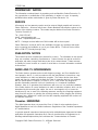
PROPRIETARY NOTICE
The information contained herein is proprietary and confidential to Patton Electronics Co.
Any reproduction or redistribution of this publication, in whole or in part, is expressly
prohibited unless written authorization is given by Patton Electronics Co.
SERVICE
All warranty and non-warranty repairs must be returned freight prepaid and insured to
Patton Electronics. All returns must have a Return Materials Authorization number on the
outside of the shipping container. This number may be obtained from Patton Electronics
Technical Services at:
Tel: (301) 975-1007;
email: [email protected];
or, Web: http://www.patton.com.
NOTE: Packages received without an RMA number will not be accepted.
Patton Electronics’ technical staff is also available to answer any questions that might
arise concerning the installation or use of your Patton MSDs. Technical Service hours:
8AM to 5PM EST, Monday through Friday.
PUBLICATION NOTICE
This manual has been compiled and checked for accuracy. The information in this manual
does not constitute a warranty of performance. Patton reserves the right to revise this
publication and make changes from time to time in the content thereof. Patton assumes
no liability for losses incurred as a result of out-of-date or incorrect information contained
in this manual.
RADIO AND TV INTERFERENCE
The Patton devices generate and use radio frequency energy, and if not installed and
used properly—that is, in strict accordance with the manufacturer’s instructions—may
cause interference to radio and television reception. The Patton devices have been
tested and found to comply with the limits for Class A computing devices in accordance
with the specifications in Subpart J of Part 15 of FCC rules, which are designed to
provide reasonable protection from such interference in a commercial installation.
However, there is no guarantee that interference will not occur in a particular installation.
If the Patton devices do cause interference to radio or television reception, which can be
determined by disconnecting the cables, the user is encouraged to try to correct the
interference by one or more of the following measures: moving the computing equipment
away from the receiver, re-orienting the receiving antenna, and/or plugging the receiving
equipment into a different AC outlet (such that the computing equipment and receiver are
on different branches).
Canadian EMISSIONS
This digital apparatus does not exceed the Class A limits for noise emissions from a
digital apparatus set out in the Radio Interference Regulations of the Canadian Department
of Communications.
Le present appareil numerique n’emet pas de bruits redioelectriques depassant les limites
applicables aux appareils numeriques de la Class A prescites dans le Reglement sur le
brouillage redioelectrique edicte par le ministere des Communications du Canada.
Copyright© 2000 Patton Electronics Co., All Rights Reserved

172001UA
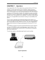
CHAPTER 1 - Operation
The Patton 2021P (CTS TCB-V.24/X.21) is an EIA RS-232 to CCITT X.21
interface converter with a built in tail circuit buffer, allowing modem to
modem interconnection. The interface converter operates bi-directionally.
DCE / DTE selection of each port permits interfacing an RS-232 terminal or
modem to an X.21 terminal or modem. This interface converter can satisfy
all interface conversion requirements. This adapter is ideal for High Speed
Modems since it can operate at up to 128Kbps. Connection of two terminal
devices is not supported because internal clocking is not provided by this
device.
Devices can be separated up to 4000 feet away from the interface con-
verter on the balanced interface side and RS-232 devices can be separated
up to 50 feet away from the interface converter. The unit is supplied with a
female DB-25 for the RS-232 port and a female DB-15 for the CCITT X.21
port.
The interface converter is housed in a sturdy aluminum enclosure and has
an internal 110/220VAC switch selectable power supply. Sixteen of the
interface converters will also fit into the MCS-16 card rack for convenient
data center applications.
The unit can operate on standard power found in most countries.
IC-V.24/X.21
X.21 Modem
1-1
Typical Application

172001UA
CHAPTER 2 - SETUP AND INSTALLATION
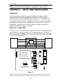
Installation
Set the switches to match the required configurations based on the
diagrams below. The cabling between each device and the interface
converter must be terminated with male connectors. J1 is the RS-232 /
V.24 interface and J2 is the X.21 interface. The IEC connector is provided
to interface to the power plug required in the country of use. Insure the
110/220VAC switch is set correctly for the line voltage in use prior to
applying power to the interface converter.
Selection of DTE/DCE
To connect an RS-232 terminal type device (DTE) to an X.21 Modem type
device (DCE), connect the terminal to J1 and the Modem to J2. Move
SW1 and SW2 to the DCE position, and SW3, SW4 and SW5 to the DTE
position, as shown in Fig. 1.
X.21 DCE V.24 DTE
RXD - 3
TX D - 2
RX C - 17
TXC - 15
S - 6, 13
T - 2, 9
R - 4, 11
X.21 DTE V.24 DCE
Buff er
RTS - 4 / DTR - 20C - 3, 10
CTS - 5 / DC D - 8
I - 5, 12
JP3JP2JP1 JP4
I
Power
T
S
R
J3
SW1
C
X.21 INTERFACE
DCE DTE
Factory Test Straps
Must be Installed for Unit To
Operate Correctly
J1 (RS-232) Is a DCE, and
MUST Connect to a
Terminal (DTE)
J2 (X.21) Is a DTE, and
MUST Connect
to a Modem (DCE)
Signal
to
Chassis
Ground
SW2
SW3
J2
X.21
J1
RS-232
JP5
JP6
DTR /RTS
DCD / CTS
SW4
SW5
DCEDTE
V.24 INTERFACE
Figure 1.
*NOTE: All clocks in the communication system must be frequency locked. One and
only one clock must be selected as master for the system. All other clocks must be
2-1
Note: Hazardous voltages are present when the equipment cover is removed.
Installation and setup shall be performed by qualified service personnel only.

172001UA
2-2
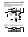
slaved to this clock.
To connect a X.21 terminal type device (DTE) to an RS-232 Modem type
device (DCE), connect the terminal to J2 and the Modem to J1. Move
SW1 and SW2 to the DTE position, and SW3, SW4 and SW5 to the DCE
position, as shown in Fig.2.
X.21 DTE
X.21 DCE V.24 DTE
TX D - 2
TXC - 15
RX C - 17
S - 6, 13
T - 2, 9 V.24 DCE
RXD - 3R - 4, 11
Buff er
RTS - 4 / DTR - 20
C - 3, 10
CTS - 5 / DC D - 8I - 5, 12
I
Power
T
S
R
J3
C
Factory Test Straps
Must be Installed for Unit To
Operate Correctly
J1 (RS-232) Is a DTE, and
MUST Connect to a
Modem (DCE)
J2 (X.21) Is a DCE, and
MUST Connect
to a Terminal (DTE)
J2
X.21
J1
RS-232
JP3JP2
JP1 JP4
SW1
X.21 INTERFACE
DCE DTE
Signal
to
Chassis
Ground
SW2
SW3
JP5
JP6
DTR /RTS
DCD / CTS
SW4
SW5
DCEDTE
V.24 INTERFACE
Figure 2.
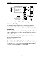
To connect a X.21 Modem type device (DCE) to an RS-232 Modem type
device (DCE), connect the X.21 Modem to J2 and the V.24 Modem to J1.
Move SW1, SW2, SW3, SW4 and SW5 to the DTE position, as shown in
Fig.3.
X.21 DCE
X.21 DTE V.24 DTE
TX D - 2
RXD - 3
RX C - 17
XT XC - 24
S - 6, 13
T - 2, 9
R - 4, 11
V.24 DCE
Buff er
RTS - 4 / DTR - 20
C - 3, 10 CTS - 5 / DC D - 8
I - 5, 12

172001UA
2-3
I
Power
T
S
R
J3
C
Factory Test Straps
Must be Installed for Unit To
Operate Correctly
J1 (RS-232) Is a DTE, and
MUST Connect to a
Modem (DCE)
J2 (X.21) Is a DTE, and
MUST Connect
to a Modem (DCE)
J2
X.21
J1
RS-232
JP3JP2
JP1 JP4
SW1
X.21 INTERFACE
DCE DTE
Signal
to
Chassis
Ground
SW2
SW3
JP5
JP6
DTR /RTS
DCD / CTS
SW4
SW5
DCEDTE
V.24 INTERFACE
Figure 3
(Factory Default Setting)
Equipment Grounding
JP4 provides grounding interconnection in those systems requiring a
connection between Frame Ground and Signal Ground. If signal ground
and chassis ground interconnection is desired, install the jumper on JP4.
LED Indicators
The Following LED indicators are provided for diagnostics: Power, Transmit
Data (T), Receive Data (R), Control (C), Indicate (I) and Signal Timing (S).
Factory Test Straps
The Factory Test Straps JP1, JP2 and JP3 must be installed for proper
operation of the interface converter.
Signal Crossover
JP5 controls selection of DTR or RTS as the active V.24 control signal.
JP6 controls selection of the DCD or CTS as the active V.24 control signal.
The selection of DTE or DCE on the two interfaces will determine which
X.21 signal is connected to which V.24 control signal.

172001UA
A-1
APPENDIX
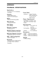
TECHNICAL SPECIFICATIONS
Applications
RS-232 to CCITT X.21 interface
conversion
Capacity
One RS-232 Channel
One CCITT X.21 Channel
Buffer
Bidirectional 8-bit ring buffer
Data Format
Transparent to Data
Data Rates
Up to 128Kbps
Electrical Interface
RS-232 and V.11
RS-232 Physical Interface
Female DB-25 (V.24) Connector
Balanced Physical Interface
Female DB-15 (V.11) Connector
DCE / DTE Configuration
Switch Selectable
Enclosure
Aluminum Shell or 1010R16/P/UI
(CTS MCS-16C) Card Rack
Assembly
Front Panel
Indicators: ... Power, Transmit
Data, Receive Data,
Control, Indicate,
Signal Timing
Power Requirements
110/220VAC, 50/ 60Hz, 0.16/
.08A, switch selectable Power
Supply
Environmental
Oper Temp: ...... 32° to 122°F (0°
to 50°C)
Rel Humidity: ... Up to 90% non-
condensing
Altitude: ...........0 to 10,000 feet
Dimensions
Height: .... 2.00 inches (5.08cm)
Width: ..... 8.80 inches (22.35cm)
Length:.... 9.80 inches (24.89cm)
Weight
2.25 lbs (1.02Kg)

172001UA
A-2
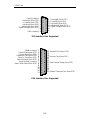
Shield (common)
Transmit(A) (from DTE)
Control(A) (from DTE)
Receive(A) (from DCE)
Indication(A) (from DCE)
Signal Timing(A) (from DCE)
GND (common)
Transmit(B) (from DTE)
Control(B) (from DTE)
Receive(B) (from DCE)
Indication(B) (from DCE)
Signal Timing(B) (from DCE)
1
2
3
4
5
6
7
8
9
10
11
12
13
14
15
X.21 Interface Pins Supported
1
2
3
4
5
6
7
8
9
10
11
12
13
14
15
16
17
18
19
20
21
22
23
24
25
Shield (common)
Transmit Data (from DTE)
Receive Data (from DCE)
Request to Send (from DTE)
Clear To Send (from DCE)
Data Set Ready (from DCE)
Signal Ground (common)
Data Carrier Detect (from DCE)
Transmit Clock (from DCE)
Receive Clock (from DCE)
Data Terminal Ready (from DTE)
External Transmit Clock (from DTE)
V.24 Interface Pins Supported

B
Sales: 301 975-1000 Support: 301 975-1007
Web Address: http://www.patton.com
7622 Rickenbacker Drive
Gaithersburg, MD 20879
-
 1
1
-
 2
2
-
 3
3
-
 4
4
-
 5
5
-
 6
6
-
 7
7
-
 8
8
-
 9
9
-
 10
10


Patton electronic CTS IC-V.24/X.21 Manuel utilisateur
- Taper
- Manuel utilisateur
- Ce manuel convient également à
dans d''autres langues
Autres documents
-
Linon Kennedy Backless Counter Stool Black Whi Assembly Instructions
-
Black Box ME662A-SST Manuel utilisateur
-
Aethra VX2000 Manuel utilisateur
-
 Allen-Bradley 1747-KE Installation Instructions Manual
-
wattstopper LMDI-100 Serial Data Interface Mode d'emploi
-
 Wavecom FASTRACK M1306B Mode d'emploi
-
Black Box TL073A-R4 Le manuel du propriétaire
-
Renkforce RS232 Le manuel du propriétaire
-
Westermo MA-29 Mode d'emploi
-
SBC SBC-SBus Le manuel du propriétaire

