
BLODGETT OVEN COMPANY
www.blodgett.com
44 Lakeside Avenue, Burlington, Vermont 05401 USA Telephone (800) 331Ć5842, (802) 860Ć3700 Fax: (802)864Ć0183
PN 38480 Rev G (8/10)
E 2010 - G.S. Blodgett Corporation
XR8ĆG and XR8ĆE
MINI RACK OVEN
INSTALLATION - OPERATION - MAINTENANCE
XR8ĆG et XR8ĆE
MINI FOUR DE SUPPORT
MANUEL D'INSTALLATION - FONCTIONNEMENT - ENTRETIEN

IMPORTANT
FOR YOUR SAFETY
Do not store or use gasoline or other flammable vapors or liquids in the vicinity
of this or any other appliance.
AVERTISSEMENT
Ne pas entreposer ni utiliser de l'essence ni d'autres vapeurs ou liquides inflamĆ
mables dans le voisinage de cet appariel, ni de tout autre appareil.
INSTRUCTIONS (PAGE 13) TO BE FOLLOWED IN THE EVENT THE USER
SMELLS GAS MUST BE POSTED IN A PROMINENT LOCATION. THIS INFORMAĆ
TION MAY BE OBTAINED BY CONTACTING YOUR LOCAL GAS SUPPLIER.
LES INSTRUCTIONS (PAGE 13) À RESPECTER AU CAS OÙ L'UTILISATEUR PERĆ
ÇOIT UNE ODEUR DE GAZ DOIVENT ÊTRE AFFICHÉES DANS UN ENDROIT BIEN
VISIBLE. VOUS POUVEZ VOUS LES PROCURER AUPRÈS DE VOTRE FOURNISĆ
SEUR DE GAZ LOCAL.
WARNING: IMPROPER INSTALLATION, ADJUSTMENT, ALTERATION, SERVICE OR
MAINTENANCE CAN CAUSE PROPERTY DAMAGE, INJURY OR DEATH. READ THE
INSTALLATION, OPERATING AND MAINTENANCE INSTRUCTIONS THOROUGHLY
BEFORE INSTALLING OR SERVICING THIS EQUIPMENT
AVERTISSEMENT: UNE INSTALLATION, UN AJUSTEMENT, UNE ALTÉRATION, UN
SERVICE OU UN ENTRETIEN NON CONFORME AUX NORMES PEUT CAUSER DES
DOMMAGES À LA PROPRIÉTE, DES BLESSURES OU LA MORT. LISEZ ATTENTIVEĆ
MENT LES DIRECTIVES D'INSTALLATION, D'OPÉRATION ET D'ENTRETIEN AVANT
DE FAIRE L'INSTALLATION OU L'ENTRETIEN DE CET ÉQUIPEMENT.
The information contained in this manual is important for the proper installation,
use, and maintenance of this oven. Adherence to these procedures and instrucĆ
tions will result in satisfactory baking results and long, trouble free service.
Please read this manual carefully and retain it for future reference.
Les informations données dans le présent manuel sont importantes pour installer,
utiliser et entretenir correctement ce four. Le respect de ces instructions et procéĆ
dures permettra d'obtenir de bons résultats de cuisson et une longue durée de serĆ
vice sans problèmes. Veuillez lire le présent manuel et le conserver pour pouvoir
vous y reporter à l'avenir.
Errors: Descriptive, typographic or pictorial errors are subject to correction. SpecificaĆ
tions are subject to change without notice.
Erreurs:Les erreurs de description, de typographie ou d'illustration font l'objet de
corrections. Les caractéristiques sont sujettes à modifications sans préavis.

THE REPUTATION YOU CAN COUNT ON
UNE RÉPUTATION SUR LAQUELLE VOUS POUVEZ COMPTER
For over a century and a half, The Blodgett Oven Company has been building
ovens and nothing but ovens. We've set the industry's quality standard for all
kinds of ovens for every foodservice operation regardless of size, application
or budget. In fact, no one offers more models, sizes, and oven applications
than Blodgett; gas and electric, fullĆsize, halfĆsize, countertop and deck, conĆ
vection, Cook'n Hold, CombiĆOvens and the industry's highest quality Pizza
Oven line. For more information on the full line of Blodgett ovens contact your
Blodgett representative.
Cela fait maintenant dessus un siècle et demi que Blodgett se spécialise dans
la fabrication de fours. Nous avons établi les normes de qualité qui s'appliĆ
quent dans l'industrie à tous les types de fours utilisés dans les services aliĆ
mentaires, quel qu'en soit la taille, l'exploitation ou le budget. En fait, ni n'offre
plus de modèles, de tailles et d'applications de fours que Blodgett. À gaz et
électriques. De tailles différentes, sur plan de travail et superposables. Qu'il
s'agisse de fours à convection, des modèles Cook'n Hold et CombiĆOven, ou
de la gamme de fours à pizzas de la plus haute qualité offerte sur le marché.
Pour de plus amples informations sur la gamme complète de fours Blodgett,
veuillez contacter votre représentant Blodgett.

Your Service Agency's Address:
Adresse de votre agence de service:
Model/Modèle:
Serial Number/Numéro de série:
Your oven was installed by/
Installateur de votre four:
Your oven's installation was checked by/
Contrôleur de l'installation de votre four:

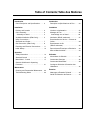
Table of Contents/Table des Matières
Introduction
Oven Description and Specifications 2. . . .
Installation
Delivery and Location 3. . . . . . . . . . . . . . . . .
Oven Assembly 4. . . . . . . . . . . . . . . . . . . . . .
Assembly to Stand 4. . . . . . . . . . . . . . . . . .
VentilationVentilation (XR8ĆG only) 5. . . . . .
Utility Connections -
Standards and Codes 7. . . . . . . . . . . . . . . . .
Gas Connection (XR8ĆG only) 8. . . . . . . . . .
Plumbing and Electrical Connections 11. . .
Initial Startup 12. . . . . . . . . . . . . . . . . . . . . . . . .
Operation
Safety Information 14. . . . . . . . . . . . . . . . . . . .
Standard Control 15. . . . . . . . . . . . . . . . . . . . .
MenuSelectt Control 17. . . . . . . . . . . . . . . . .
General Guidelines for Operating
Personnel 21. . . . . . . . . . . . . . . . . . . . . . . . . . . .
Maintenance
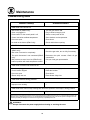
Cleaning and Preventative Maintenance 22.
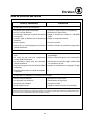
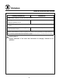
Troubleshooting Guide 23. . . . . . . . . . . . . . . .
Introduction
Description et Spécifications du Four 24. . . .
Installation
Livraison et Implantation 25. . . . . . . . . . . . . . .
Montage du Four 26. . . . . . . . . . . . . . . . . . . . .
Assemblage sur un Stand 26. . . . . . . . . . . .
Ventilation (XR8ĆG seulement) 27. . . . . . . . . .
Branchements de Service - Normes et
Codes 29. . . . . . . . . . . . . . . . . . . . . . . . . . . . . . .
Branchement de Ga
(XR8ĆG seulement) 30. . . . . . . . . . . . . . . . . . .
Raccordement Électrique et Plomberie 33. .
Mise en Marche Initiale 34. . . . . . . . . . . . . . . .
Utilisation
Informations de Sécurité 35. . . . . . . . . . . . . . .
Commande Classique 36. . . . . . . . . . . . . . . . .
Commande MenuSelectt 38. . . . . . . . . . . . .
Consignes Générales à l'Intention des
Utilasateurs 42. . . . . . . . . . . . . . . . . . . . . . . . . .
Entretien
Nettoyage et Entretien Préventif 43. . . . . . . .
Guide de Détection des Pannes 44. . . . . . . .

Introduction
2
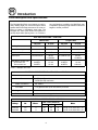
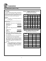
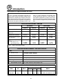
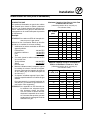
Oven Description and Specifications
The Blodgett MiniĆRack oven features a continuĆ
ously rotating eight pan rack and unique airflow
system that moves large amounts of air at low veĆ
locity to ensure a consistently even bake. The
Blodgett rack slide sytem allows the operator to
quickly adjust slide spacing from 1 to 4 inches in
any configuration. In addition, the MiniĆRack oven
is capable of producing large volumes of steam for
bagels or similar products.
GAS SPECIFICATIONS - XR8ĆG/AB
Natural Gas Propane Gas
US Units SI Units US Units SI Units
Heating Value 1000 BTU/cu. ft. 37.3 MJ/m
3
2550 BTU/cu. ft. 95.0 MJ/m
3
Specific Gravity (air=1.0) 0.63 0.63 1.53 1.53
Gas Manifold Pressure 3.5" W.C. .87 kPa 10" W.C. 2.5 kPa
Oven Input 110,000 BTU/hr 32 kW
116 MJ/hr
110,000 BTU/hr 32 kW
116 MJ/hr
Main Burner Orifice Size:
Six burners are
Two burners are
50 MTD*
53 MTD*
1.7 mm
1.5 mm
57 MTD*
62 MTD*
1.0 mm
0.96 mm
* MTD - Multiple Twist Drill
PLUMBING SPECIFICATIONS - XR8ĆG/AB and XR8ĆE/AA
Water
Water Pressure 30 PSI (21 kPa) minimum
75 PSI (52 kPa) maximum
Water Connection 3/4" MGHT
Flow Rate 1.12 gallon/minute (4.24 litre/minute) minimum
Drainage
Drain Connection 3/4" rear drain to air gap drain
ELECTRICAL SPECIFICATIONS - XR8ĆE/AA
Vlt
H
Ph
Max. Load (Amperes)
Mt
Voltage Hz Phase
L1 L2 L3
Motor
208 VAC 60 3 52 52 52 1/4 HP, 115V, 50/60 Hz, 1 ph
240 VAC 60 3 46 46 46 1/4 HP, 115V, 50/60 Hz, 1 ph

Installation
3
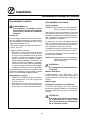
Delivery and Location
DELIVERY AND INSPECTION
All Blodgett ovens are shipped in containers to
prevent damage. Upon delivery of your new oven:
D Inspect the shipping container for external damĆ
age. Any evidence of damage should be noted
on the delivery receipt which must be signed by
the driver.
D Uncrate the oven and check for internal damĆ
age. Carriers will accept claims for concealed
damage if notified within fifteen days of delivery
and the shipping container is retained for inĆ
spection.
The Blodgett Oven Company cannot assume
responsibility for loss or damage suffered in
transit. The carrier assumed full responsibility
for delivery in good order when the shipment
was accepted. We are, however, prepared to
assist you if filing a claim is necessary.
OVEN LOCATION
The well planned and proper placement of your
oven will result in long term operator convenience
and satisfactory performance.
The following clearances must be maintained beĆ
tween the oven and any combustible or nonĆcomĆ
bustible construction.
D Oven body right side - 0" (0 cm)
D Oven body left side - 0" (0 cm)
D Oven body back - 0" (0 cm)
D Oven top - 12" (30.5 cm)
The following clearances must be available for serĆ
vicing.
D Oven body sides - 12" (30 cm)
D Oven body back - 12" (30 cm)
D Oven top - 12" (30.5 cm)
NOTE: On gas models, routine servicing can usuĆ
ally be accomplished within the limited
movement provided by the gas hose reĆ
straint. If the oven needs to be moved furĆ
ther from the wall, the gas must first be
turned off and disconnected from the oven
before removing the restraint. Reconnect
the restraint after the oven has been reĆ
turned to its normal position.
It is essential that an adequate air supply to the
oven be maintained to provide a sufficient flow of
combustion and ventilation air.
D Place the oven in an area that is free of drafts.
D Keep the oven area free and clear of all combusĆ
tibles such as paper, cardboard, and flammable
liquids and solvents.
D Do not place the oven on a curb base or seal to
a wall. This will restrict the flow of air and prevent
proper ventilation. Tripping of the blower moĆ
tor's thermal overload device is caused by an
excessive ambient temperature on the right
side of the oven. This condition must be corĆ
rected to prevent permanent damage to the
oven.
D The location must provide adequate clearance for
the air opening into the burners.
Before making any utility connections to this oven,
check the rating plate to be sure the oven specifiĆ
cations are compatible with the gas and electrical
services supplied for the oven.
1. The rating plate is located behind the control
panel.
2. Remove the two screws on the right side of the
control panel.
3. Pull the control panel toward the right side of
the oven.
4. Pull the control panel away from the oven and
rotate out.
5. Reverse steps 2Ć4 to close the control panel.

Installation
4
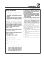
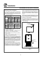
Oven Assembly
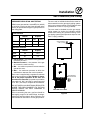
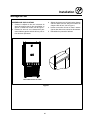
ASSEMBLY TO STAND
1. Center the oven frame on top of the stand so
that the oven overhangs at both the front and
back. See Figure 1.
2. Remove the three screws at the top of the left
and right side panels of the oven. Remove the
side panels.
3. Align the two bolt holes on each side of the
stand with the two threaded holes on each
side of the oven. See Figure 1.
4. Insert a bolt from the bottom up through each
of the two holes and tighten securely.
5. Reinstall the side panels.
SIDE VIEW WITH STAND
Figure 1

Installation
5
VentilationVentilation (XR8ĆG only)
On gas models the installation of a proper ventilaĆ
tion system cannot be over emphasized. This sysĆ
tem removes unwanted vapors and products of
combustion from the operating area.
U.S. and Canadian installations
Refer to your local ventilation codes. In the abĆ
sence of local codes, refer to the National ventilaĆ
tion code titled, Standard for the Installation of
Equipment for the Removal of Smoke and Grease
Laden Vapors from Commercial Cooking EquipĆ
ment", NFPAĆ96ĆLatest Edition.
General export installations
Installation must conform with Local and National
installation standards. Local installation codes
and/or requirements may vary. If you have any
questions regarding the proper installation and/or
operation of your Blodgett oven, please contact
your local distributor. If you do not have a local disĆ
tributor, please call the Blodgett Oven Company at
0011Ć802Ć860Ć3700.
WARNING:
Failure to properly vent the oven can be
hazardous to the health of the operator
and may result in operational problems,
unsatisfactory baking and possible damĆ
age to the equipment.
Damage sustained as a direct result of imĆ
proper ventilation will not be covered by
the manufacturer's warranty.
When installed in the Commonwealth of MassaĆ
chusetts, this appliance must be interlocked with
the hood exhaust system so that the appliance
may be operated only when the hood exhaust sysĆ
tem is running.
CANOPY TYPE EXHAUST HOOD
A mechanically driven, canopy type exhaust hood
is the preferred method of ventilation. The exhaust
fan should have an interlock switch with the oven
to prevent the oven from operating when the exĆ
haust fan is not running.
The hood should be sized to completely cover the
equipment plus an overhang of at least 6" (15 cm)
on all sides not adjacent to a wall. The distance
from the floor to the lower edge of the hood should
not exceed 7' (2.1m).
The total makeup and exhaust air requirements for
hood capacity should be approximately 35 CFM
(.99 m
3
/min).

Installation
6
Ventilation (XR8ĆG only)
DIRECT FLUE ARRANGEMENT
When the installation of a mechanically driven exĆ
haust hood is impractical the oven may be vented
by a direct flue arrangement.
WARNING!!
It is essential that the direct flue be
installed as follows. Incorrect installation
will result in unsatisfactory baking and
oven damage.
The flue must be 6" (15 cm) diameter, class B or betĆ
ter. The height of the flue should be compliant with
the current revision of NFPA 54, Ansi Z223.1. Never
direct vent the oven into a hood. The flue should be
capped with a UL Listed type vent cap to isolate the
unit from external environmental conditions.
The direct vent cannot replace air consumed and
vented by the oven. Provisions must be made to
supply the room with sufficient makeĆup air. Total
makeĆup air requirements for each oven section
should be approximately 35 CFM (.99 m
3
/min). To
increase the supply air entering the room, a venĆ
tilation expert should be consulted.
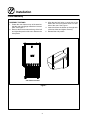
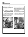
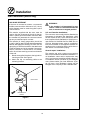
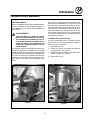
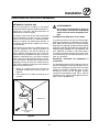
Installing the draft hood
Ovens ordered for direct venting are supplied with
a draft hood. Install the draft hood as follows:
1. Disconnect power to the oven.
2. Remove the two screws holding the exhaust
guard. See Figure 2.
3. Install the draft hood using the screws reĆ
moved in step 2. See Figure 3.
4. Reconnect power to the oven.
Figure 2
Figure 3

Installation
7
Utility Connections - Standards and Codes
THE INSTALLATION INSTRUCTIONS CONTAINED
HEREIN ARE FOR THE USE OF QUALIFIED INĆ
STALLATION AND SERVICE PERSONNEL ONLY.
INSTALLATION OR SERVICE BY OTHER THAN QUĆ
ALIFIED PERSONNEL MAY RESULT IN DAMAGE
TO THE OVEN AND/OR INJURY TO THE OPERAĆ
TOR.
Qualified installation personnel are individuals, a
firm, a corporation, or a company which either in
person or through a representative are engaged
in, and responsible for:
D the installation or replacement of gas piping
and the connection, installation, repair or servĆ
icing of equipment.
D the installation of electrical wiring from the elecĆ
tric meter, main control box or service outlet to
the electric appliance.
Qualified installation personnel must be experiĆ
enced in such work, familiar with all precautions
required, and have complied with all requirements
of state or local authorities having jurisdiction.
U.S. and Canadian installations
Installation must conform with local codes, or in
the absence of local codes, with the ANSI Z83.11aĆ
CSA 1.8aĆ2004 Gas Food Service Equipment as
applicable.
Installation must conform with local codes, or in
the absence of local codes, with the National ElecĆ
trical Code, ANSI/NFPA 70-Latest Edition and/or
CSA 22.1 as applicable.
Appliance is to be installed with backflow prevenĆ
tion in accordance with applicable federal, provĆ
ince and local codes.
General export installations
Installation must conform with Local and National
installation standards. Local installation codes
and/or requirements may vary. If you have any
questions regarding the proper installation and/or
operation of your Blodgett oven, please contact
your local distributor. If you do not have a local disĆ
tributor, please call the Blodgett Oven Company at
0011Ć802Ć860Ć3700.

Installation
8
Gas Connection (XR8ĆG only)
GAS PIPING
A properly sized gas supply system is essential for
maximum oven performance. Piping should be
sized to provide a supply of gas sufficient to meet
the maximum demand of all appliances on the line
without loss of pressure at the equipment.
Example:
NOTE: BTU values in the following example are
for natural gas.
You purchase a XR8ĆG rack oven to add to your exĆ
isting cook line.
1. Add the BTU rating of your current appliances.
Pitco Fryer 120,000 BTU
6 Burner Range 60,000 BTU
Deck Oven 50,000 BTU
Total 230,000 BTU
2. Add the BTU rating of the new oven to the toĆ
tal.
Previous Total 230,000 BTU
XR8ĆG 110,000 BTU
New Total 340,000 BTU
3. Measure the distance from the gas meter to
the cook line. This is the pipe length. Let's say
the pipe length is 30' (9.1 m) and the pipe size
is 1" (2.54 cm).
4. Use the appropriate table to determine the toĆ
tal capacity of your current gas piping.
The total capacity for this example is 375,000
BTU. Since the total required gas pressure,
340,000 BTU is less than 375,000 BTU, the
current gas piping will not have to be inĆ
creased.
NOTE: The BTU capacities given in the tables are
for straight pipe lengths only. Any elbows
or other fittings will decrease pipe capaciĆ
ties. Contact your local gas supplier if you
have any questions.
Maximum Capacity of Iron Pipe in Cubic Feet
of Natural Gas Per Hour
(Pressure drop of 0.5 Inch W.C.)
Pipe
L th (ft)
Nominal Size, Inches
p
Length (ft)
3/4" 1" 1Ć1/4" 1Ć1/4" 2"
10 360 680 1400 2100 3950
20 250 465 950 1460 2750
30 200 375 770 1180 2200
40 170 320 660 990 1900
50 151 285 580 900 1680
60 138 260 530 810 1520
70 125 240 490 750 1400
80 118 220 460 690 1300
90 110 205 430 650 1220
100 103 195 400 620 1150
From the National Fuel Gas Code Part 10 Table 10Ć2
Maximum Capacity of Pipe in Thousands of
BTU/hr of Undiluted L.P. Gas at 11" W.C.
(Pressure drop of 0.5 Inch W.C.)
Pipe Length
(ft)
Outside Diameter, Inches
pg
(ft)
3/4" 1" 1Ć1/2"
10 608 1146 3525
20 418 788 2423
30 336 632 1946
40 287 541 1665
50 255 480 1476
60 231 435 1337
70 215 404 1241
80 198 372 1144
90 187 351 1079
100 175 330 1014
From the National Fuel Gas Code Part 10 Table 10Ć15

Installation
9
Gas Connection (XR8ĆG only)
PRESSURE REGULATION AND TESTING
XR8ĆG ovens are rated at 110,000 BTU/Hr. (32 kW)
(116 MJ/hr). Each oven has been adjusted at the
factory to operate with the type of gas specified on
the rating plate.
Inlet Pressure
Natural Propane
Min Max Min Max
W.C. 6.0 14.0 11.0 14.0
kPa 1.2 3.5 2.7 3.5
Manifold Pressure
Natural Propane
W.C. 3.5 10.0
kPa .87 2.5
D Inlet Pressure - the pressure of the gas before
it reaches the oven.
D Manifold Pressure - the pressure of the gas
as it enters the main burner(s).
D Min - the minimum pressure recommended to
operate the oven.
D Max - the maximum pressure at which the
manufacturer warrants the oven's operation.
Each oven is supplied with a regulator to maintain
the proper gas pressure. The regulator is essenĆ
tial to the proper operation of the oven and
should not be removed. It is preset to provide the
oven with 3.5" W.C. (.87 kPa) for natural gas and
10.0" W.C. (2.5 kPa) for Propane at the manifold.
DO NOT INSTALL AN ADDITIONAL REGULATOR
WHERE THE OVEN CONNECTS TO THE GAS
SUPPLY UNLESS THE INLET PRESSURE IS
ABOVE MAXIMUM.
Prior to connecting the oven, gas lines should be
thoroughly purged of all metal filings, shavings,
pipe dope, and other debris. After connection, the
oven should be checked for correct gas pressure.
The oven and its individual shutoff valve must be
disconnected from the gas supply piping system
during any pressure testing of that system at test
pressures in excess of 1/2 psig (3.45kPa).
The oven must be isolated from the gas supply
piping system by closing its individual manual
shutoff valve during any pressure testing of the
gas piping system at test pressures equal or less
than 1/2 psig (3.45kPa).
Gas Connection
2.78" (71 mm)
Gas Connection
37.83 (961mm)
SIDE VIEW WITH STAND
Figure 4

Installation
10
Gas Connection (XR8ĆG only)
GAS HOSE RESTRAINT
If the oven is mounted on casters, a commercial
flexible connector with a minimum of 3/4" (1.9 cm)
inside diameter must be used along with a quick
connect device.
The restraint, supplied with the oven, must be
used to limit the movement of the unit so that no
strain is placed upon the flexible connector. With
the restraint fully stretched the connector should
be easy to install and quick connect.
The restraint (ie: heavy gauge cable) should be
1,000 lb. (453 kg) test load and should be attached
without damaging the building. DO NOT use the
gas piping or electrical conduit for the attachment
of the permanent end of the restraint! Use anchor
bolts in concrete or cement block. On wooden
walls, drive hi test wood lag screws into the studs
of the wall.
1. Mount the supplied bracket to the leg bolt beĆ
low the gas inlet. See Figure 5.
2. Attach the clip on restraining cable to the
mounting bracket.
Restraint Cable
Bracket
Back of Oven
Figure 5
WARNING!!
If the restraint is disconnected for any
reason it must be reconnected when the
oven is returned to its original position.
U.S. and Canadian installations
The connector must comply with the Standard for
Connectors for Movable Gas Appliances, ANSI
Z21.69S CSA 6.16 and a quick disconnect device
that complies with the Standard for QuickĆDisconĆ
nect Devices for Use With Gas Fuel, ANSI Z21.41S
CSA 6.9. Adequate means must be provided to
limit the movement of the appliance without deĆ
pending on the connection and the quick disconĆ
nect device or its associated piping.
General export installations
The restraint and quick connect must conform
with Local and National installation standards. LoĆ
cal installation codes and/or requirements may
vary. If you have any questions regarding the propĆ
er installation and/or operation of your Blodgett
oven, please contact your local distributor. If you
do not have a local distributor, please call the
Blodgett Oven Company at 0011Ć802Ć860Ć3700.

Installation
11
Plumbing and Electrical Connections
PLUMBING CONNECTIONS
WARNING!!
Plumbing connections must comply with
applicable sanitary, safety and plumbing
codes.
Water Connections
Water supply should meet the following condiĆ
tions. Consult your local water company before
installing the oven.
D Hardness of 4Ć6 grains per gallon (100ppm max)
D PH of 6.5 to 8.0
D Chlorides less than 30 PPM
1. Connect the cold water supply to the 3/4"
MGHT connection on the back of the oven
with the water line provided. Supply pressure
should be 30 to 75 psi (207 to 517 kPa) when
the steam solenoid is open. The water regulaĆ
tor on the oven itself has been preset at the
factory. Adjust if necessary to obtain 27 GPH
(gallons per hour) from the flow meter.
This product must be installed by a licensed
Plumber or Gas Fitter when installed within the
Commonwealth of Massachusetts.
Drain Connections
1. Connect drain line to the 3/4" NPT drain conĆ
nection on the back of the oven.
2. Route the drain line to a floor drain. Allow a 1"
air gap between the drain line and the floor
drain.
ELECTRICAL CONNECTIONS
All Models
NOTE: Electrical connections must be performed
by a qualified installer only.
Before making any electrical connections to these
appliances, check that the power supply is adeĆ
quate for the voltage, amperage, and phase reĆ
quirements stated on the rating name plate
mounted on the appliance.
The circuit breaker that is used to provide power
to this appliance must have a minimum of .076"
(3mm) contact spacing. The circuit breaker must
meet all Local and National installation standards.
All appliances must be installed in accordance
with Local or National Electrical codes.
A wiring schematic is located on the inside of the
removeable side panel.
NOTE: Disconnect the power supply to the apĆ
pliance before servicing.
WARNING!!
Improper installation may invalidate your
warranty.
Electric Models
The installer must supply a cord that meets all Local
and National installation standards.
Gas Models
U.S. and Canadian Installations
A power cord (115V units only) is supplied with a
plug attached. Plug the power cord into the deĆ
sired receptacle.
WARNING!!
If the supply cord is damaged, it must be
replaced by a special cord or assembly
available from the manufacturer or its serĆ
vice agent.

Installation
12
Initial Startup
The following is a checkĆlist to be completed by
qualified personnel prior to turning on the
appliance for the first time.
j Verify there are no gas leaks, by checking all
gas connections with a soapy water solution.
Repair leaks if necessary. (XR8ĆG only)
j Verify there are no water leaks to the oven. ReĆ
pair leaks if necessary.
j Verify rack rotation as follows: Open oven
doors and turn the power switch to ON. Close
the doors and enter bake time of two minutes.
Press start. Verify the rack rotates smoothly.
Open the doors. Verify the rack stops square
to the door opening. If rack does not rotate
and fan does not circulate, door switch may
be out of adjustment.
With the main burner on, check the following:
j Set the oven temperature to 300_F. Verify that
the oven comes up to set temperature.
j Set a steam time of 20 seconds. Verify that the
flowmeter has enough water to produce 27
GPH (gallons per hour) when the water soleĆ
noid valve is open. Adjust the oven pressure
regulator if needed. The water pressure
gauge, regulator and flowmeter are located
behind the right side panel of the oven. Panel
must be removed.
j Verify that the gas inlet pressure is correct.
The inlet pressure can be checked at the presĆ
sure tap located on the gas valve. (XR8ĆG
only)
j Verify that the manifold pressure is correct.
The manifold pressure can be checked at the
outlet pressure tap located on the burner gas
manifold elbow located on top of the oven.
(XR8ĆG only)
j If the above pressure readings are set to the
recommended pressure requirements, allow
the oven to burnĆoff for two hours with oven
vent opened. If the pressure readings are not
set correctly, turn off the oven and readjust acĆ
cordingly. Then recheck pressure readings.
WARNING
The break in procedure burns off excess
oils present in the metals during fabricaĆ
tion. Smoke may be produced. Proper
ventilation is required.
ADJUSTMENTS ASSOCIATED WITH INITIAL
INSTALLATION
Each oven, and its component parts, have been
thoroughly tested and inspected prior to shipĆ
ment. However, it is often necessary to further test
or adjust the oven as part of a normal and proper
installation. These adjustments are the responsiĆ
bility of the installer, or dealer. Since these adjustĆ
ments are not considered defects in material or
workmanship, they are not covered by the Original
Equipment Warranty. They include, but are not
limited to:
D calibration of the thermostat
D adjustment of the doors
D burner adjustments (XR8ĆG only)
D leveling
D testing of gas pressure (XR8ĆG only)
D tightening of fasteners
D rack rotation stop position
No installation should be considered complete
without proper inspection, and if necessary, adĆ
justment by qualified installation or service perĆ
sonnel.

Operation
13
Safety Information
THE INFORMATION CONTAINED IN THIS SECĆ
TION IS PROVIDED FOR THE USE OF QUALIFIED
OPERATING PERSONNEL. QUALIFIED OPERATĆ
ING PERSONNEL ARE THOSE WHO HAVE
CAREFULLY READ THE INFORMATION CONĆ
TAINED IN THIS MANUAL, ARE FAMILIAR WITH
THE FUNCTIONS OF THE OVEN AND/OR HAVE
HAD PREVIOUS EXPERIENCE WITH THE OPĆ
ERATION OF THE EQUIPMENT DESCRIBED. ADĆ
HERENCE TO THE PROCEDURES RECOMĆ
MENDED HEREIN WILL ASSURE THE
ACHIEVEMENT OF OPTIMUM PERFORMANCE
AND LONG, TROUBLEĆFREE SERVICE.
Please take the time to read the following safety
and operating instructions. They are the key to the
successful operation of your Blodgett mini rack
oven.
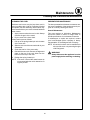
SAFETY TIPS
For your safety read before operating
What to do if you smell gas (XR8ĆG only):
D DO NOT try to light any appliance.
D DO NOT touch any electrical switches.
D Use an exterior phone to call your gas supplier
immediately.
D If you cannot reach your gas supplier, call the
fire department.
What to do in the event of a power failure:
1. Turn all switches to off.
2. DO NOT attempt to operate the oven until the
power is restored.
NOTE: In the event of a shutĆdown of any kind, alĆ
low a five (5) minute shut off period before
attempting to restart the oven.
General safety tips:
D DO NOT use tools to turn off the gas control. If
the gas cannot be turned off manually do not try
to repair it. Call a qualified service technician.
(XR8ĆG only)
D If the oven needs to be moved for any reason
disconnect the water. The gas must be turned
off and disconnected from the unit before reĆ
moving the restraint cable. Reconnect the reĆ
straint after the oven has been returned to its
original location.
D DO NOT remove the control panel cover or right
body panel unless the oven is unplugged.
D The rack will stop/finish rotating when the doors
are opened.

Operation
14
Standard Control
2
3
4
5
6
8
7
10
9
12
11
1
13
Figure 6
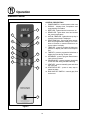
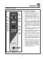
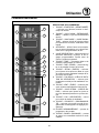
CONTROL DESCRIPTION
1. POWER SWITCH Ć controls power to the oven
2. DISPLAY Ć displays time, temperature and
programming information
3. HEAT LED Ć lights when the burners are on
4. READY LED Ć lights when oven has reached
the preset temperature
5. ACTUAL TEMP LED Ć lights when temp key is
pressed, actual temp is displayed
6. SELECTION DIAL Ć use to enter time, temperĆ
ature and programmable settings. Turn clockĆ
wise to increase or counterĆclockwise to deĆ
crease values in display.
7. TEMP KEY Ć press to program the bake temĆ
perature or display the actual oven temperaĆ
ture
8. TIME KEY Ć press to program the bake time or
display the time during a bake cycle
9. STEAM KEY Ć press to program steam time to
inject a burst of steam
10. FAN DELAY KEY Ć press to program a time delay
for fan and heat during and after steaming
11. VENT KEY Ć press to manually open and close
the oven vent
12. START/STOP KEY Ć press to start, stop or
pause the bake
13. GAS SHUTOFF SWITCH Ć controls gasy flow
to the oven

Operation
15
Standard Control
OPERATION
Oven Startup
1. Be sure the GAS SHUTOFF SWITCH (13) is in
the on position.
2. Turn the POWER SWITCH (1) to the on posiĆ
tion. The HEAT LED (3) lights and the oven
preheats to the last used set temperature.
Programming a Bake Cycle
1. Press the TEMP KEY (7). Turn the DIAL (6) to
the desired bake temperature.
2. Press the TIME KEY (8). Turn the DIAL (6) to
the desired bake time.
3. If steam is desired, press the STEAM KEY (9).
Turn the DIAL (6) to the desired steam time.
Steam may be programmed for the beginning
of the bake cycle for up to two minutes.
4. If you wish to delay the rotation of the convecĆ
tion fan at the beginning of the bake cycle,
press the FAN DELAY (10) key. Turn the DIAL
(6) to the desired fan delay time.
5. Press the START/STOP KEY (12) to begin the
bake cycle. The oven rack rotates.
During the Bake Cycle
1. To view the remaining bake time, press the
TIME KEY (8).
2. To view the actual oven temperature, press
the TEMP KEY (7).
3. To inject up to two minutes of steam during the
bake cycle, press the STEAM KEY (9).
4. To vent moisture from the oven cavity, press
the VENT KEY (11). This manually opens the
oven vent until the key is pressed again to
close it.
5. To pause a bake cycle at any point, press the
START/STOP KEY (12). The cycle will pause
until the key is pressed again.
At the End of the Bake Cycle
1. At the end of the bake cycle, an alarm sounds,
the display reads DONE and the rack continĆ
ues to rotate until the door is opened. Press
the START/STOP KEY (12) to silence the
alarm.
2. Open the door to remove the product.
Cool Down
1. Press the TEMP KEY (7). Turn the DIAL (6) to
below 150_F.
NOTE: The doors may be opened to speed the
cooling process.
Oven Shutdown
1. Turn the POWER SWITCH (1) to the off posiĆ
tion.

Operation
16
MenuSelectt Control
1
4
3
5
6
8
11
14
7
9
10
2
17
12
13
16
15
Figure 7
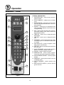
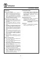
CONTROL DESCRIPTION
1. START/STOP KEY Ć press to start, cancel or
pause the bake
2. COOL DOWN KEY Ć initiates oven cool down
cycle
3. BAKE MORE KEY Ć press at the end of a bake
cycle to add additional bake time in one minĆ
ute increments.
4. DISPLAY Ć displays time or temperature and
other information related to oven function and/
or programming.
5. DIAL Ć used to enter set points, time, and proĆ
grammable settings. Also used to select the
programmed product.
6. TEMP KEY Ć used to set or change the bake
temperature
7. TIME KEY Ć used to set or change the bake
time.
8. STEAM KEY Ć used to inject steam at the start
of the bake cycle or to override the steam time
in a recipe.
9. FAN DELAY KEY Ć press to program a time
delay for the convection fan
10. VENT KEY Ć press to manually open and close
the oven vent
11. QUICK STEAM KEY Ć press to inject a burst of
steam on demand during a bake cycle.
12. FAN KEY Ć press to select fan speed.
13. PROG/EXIT KEY Ć press to enter programĆ
ming mode and save programmed settings.
14. ALPHA/NUMERIC KEYPAD Ć used to program
recipes.
15. POWER KEY Ć used to place control in and out
of standby mode.
16. CIRCUIT BREAKER Ć controls power to the
oven.
17. HEAT SHUTOFF SWITCH Ć press to shut off
gas to the oven.
La page est en cours de chargement...
La page est en cours de chargement...
La page est en cours de chargement...
La page est en cours de chargement...
La page est en cours de chargement...
La page est en cours de chargement...
La page est en cours de chargement...
La page est en cours de chargement...
La page est en cours de chargement...
La page est en cours de chargement...
La page est en cours de chargement...
La page est en cours de chargement...
La page est en cours de chargement...
La page est en cours de chargement...
La page est en cours de chargement...
La page est en cours de chargement...
La page est en cours de chargement...
La page est en cours de chargement...
La page est en cours de chargement...
La page est en cours de chargement...
La page est en cours de chargement...
La page est en cours de chargement...
La page est en cours de chargement...
La page est en cours de chargement...
La page est en cours de chargement...
La page est en cours de chargement...
La page est en cours de chargement...
La page est en cours de chargement...
La page est en cours de chargement...
-
 1
1
-
 2
2
-
 3
3
-
 4
4
-
 5
5
-
 6
6
-
 7
7
-
 8
8
-
 9
9
-
 10
10
-
 11
11
-
 12
12
-
 13
13
-
 14
14
-
 15
15
-
 16
16
-
 17
17
-
 18
18
-
 19
19
-
 20
20
-
 21
21
-
 22
22
-
 23
23
-
 24
24
-
 25
25
-
 26
26
-
 27
27
-
 28
28
-
 29
29
-
 30
30
-
 31
31
-
 32
32
-
 33
33
-
 34
34
-
 35
35
-
 36
36
-
 37
37
-
 38
38
-
 39
39
-
 40
40
-
 41
41
-
 42
42
-
 43
43
-
 44
44
-
 45
45
-
 46
46
-
 47
47
-
 48
48
-
 49
49


