Paradigm PDR 100 Le manuel du propriétaire
- Catégorie
- Équipement musical supplémentaire
- Taper
- Le manuel du propriétaire

Paradigm Electronics Inc. In Canada: 205 Annagem Blvd., Mississauga, ON L5T 2V1 • In the U.S.: MPO Box 2410, Niagara Falls, NY 14302
080410
Thank you for choosing Paradigm PDR subwoofers and congratulations! You
are about to hear the difference these high-performance subwoofers will make in
your music and home theater system. They are the product of countless hours of
comprehensive research and development and will reward you with superior high-
end sound for many years.
To achieve all of the exceptional sound they are capable of providing requires care
in installation and operation. Please take the time to read this manual and follow all
instructions. If you have further questions, please contact your Authorized
Paradigm Dealer or visit the Q&A page on our website at www.paradigm.com.
®
THE ULTIMATE IN SOUND FOR MUSIC AND HOME THEATER
TM
WIRELESS
PDR SUBWOOFER SERIES
OWNERS MANUAL
Includes
model

Safety Precautions . . . . . . . . . . . . 2
Important Safety Instructions . . . 3
Back-Panel: Controls and
Connections (Pictorial) . . . . . . . . . 4
Subwoofer Placement
(Pictorial) . . . . . . . . . . . . . . . . . . . . 6
Connecting Your
Subwoofer (Pictorial) . . . . . . . . . . 6
Pairing Your Wireless Subwoofer
with the Transmitter (Pictorial) . . 7
Your New Subwoofer . . . . . . . . . . 8
Power Requirements . . . . . . . . . . 8
Room Acoustics . . . . . . . . . . . . . . 8
Subwoofer Placement . . . . . . . . . 8
Wireless Operation . . . . . . . . . . . . 9
Subwoofer Connection . . . . . . . .10
Fine Tuning . . . . . . . . . . . . . . . . . .10
Specifications . . . . . . . . . . . . . . . .12
Limited Warranty . . . . . . . . . . . . .13
TABLE OF CONTENTS
RECYCLING AND REUSE GUIDELINES FOR EUROPE
In accordance with the European Union WEEE (Waste Electrical and Electronic Equipment) directive effective August
13, 2005, we would like to notify you that this product may contain regulated materials which, upon disposal,
according to the WEEE directive, require special reuse and recycling processing. For this reason Paradigm
Electronics Inc. (manufacturers of Paradigm speakers and Anthem electronics) has arranged with our distributors in
European Union member nations to collect and recycle this product at no cost to you. To find your local distributor
please contact the dealer from whom you purchased this product or go to our website at www.paradigm.com.
Please note that the product only falls under the WEEE directive. When disposing of packaging and other shipping
material we encourage you to recycle through the normal channels.
FCC ID: WU0-WRX1010. This device complies with Part 15 of the FCC Rules. Operation is subject to the following two conditions:
(1) This device may not cause harmful interference, and (2) This device must accept any interference received, including information that
may cause undesired operation. Changes or modifications not expressly approved by the party responsible for compliance could void the
user’s authority to operate the equipment.

2
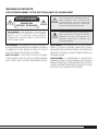
SAFETY PRECAUTIONS
READ THIS SECTION CAREFULLY BEFORE PROCEEDING!
WARNING: TO REDUCE THE RISK OF ELECTRIC SHOCK, DO
NOT REMOVE COVER (OR BACK). NO USER-SERVICEABLE
PARTS INSIDE. REFER SERVICING TO QUALIFIED SERVICE
PERSONNEL.
The lightning flash with arrowhead symbol within an
equilateral triangle, is intended to alert the user to the
presence of uninsulated “Dangerous voltage” within the
product’s enclosure that may be of sufficient magnitude
to constitute a risk of electric shock to persons.
The exclamation point within an equilateral triangle
is intended to alert the user to the presence of important
operating and maintenance (Servicing) instructions in
the literature accompanying the product.
WARNING: TO REDUCE THE RISK OF FIRE OR ELECTRIC SHOCK,
DO NOT EXPOSE THIS APPARATUS TO RAIN OR MOISTURE, AND
OBJECTS FILLED WITH LIQUIDS, SUCH AS VASES, SHOULD NOT
BE PLACED ON THIS APPARATUS.
CAUTION: TO PREVENT ELECTRIC SHOCK, MATCH WIDE BLADE
OF PLUG TO WIDE SLOT, FULLY INSERT.
CAUTION: FOR CONTINUED PROTECTION AGAINST RISK OF FIRE,
REPLACE THE FUSE ONLY WITH THE SAME AMPERAGE AND
VOLTAGE TYPE. REFER REPLACEMENT TO QUALIFIED SERVICE
PERSONNEL.
WARNING: UNIT MAY BECOME HOT. ALWAYS PROVIDE ADEQUATE
VENTILATION TO ALLOW FOR COOLING. DO NOT PLACE NEAR A
HEAT SOURCE, OR IN SPACES THAT CAN RESTRICT VENTILATION.
WARNING
RISK OF ELECTRIC SHOCK
DO NOT OPEN

3
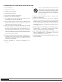
IMPORTANT SAFETY INSTRUCTIONS
1) Read these instructions.
2) Keep these instructions.
3) Heed all warnings.
4) Follow all instructions.
5) Do not use this apparatus near water.
6) Clean only with dry a cloth.
7) Do not block any ventilation openings. Install in accordance with the
manufacturer’s instructions.
8) Do not install near any heat sources such as radiators, heat registers,
stoves, or other apparatus (including amplifiers) that produce heat.
9) Do not defeat the safety purpose of the polarized or grounding-type
plug. A polarized plug has two blades with one wider than the other.
A grounding type plug has two blades and a third grounding prong.
The wide blade or the third prong are provided for your safety. If the
provided plug does not fit into your outlet, consult an electrician for
replacement of the obsolete outlet.
10) Protect the power cord from being walked on or pinched particularly
at plugs, convenience receptacles, and the point where they exit
from the apparatus.
11) Only use attachments/accessories specified by the manufacturer.
12) Use only with the cart, stand, tripod, bracket, or table
specified by the manufacturer or sold with the apparatus.
When a cart is used, use caution when moving the cart/
apparatus combination, to avoid injury from tip-over.
13) Unplug this apparatus during lightning storms or when unused for
long periods of time.
14) Refer all servicing to qualified service personnel. Servicing is required
when the apparatus has been damaged in any way, such as power-
supply cord or plug is damaged, liquid has been spilled or objects
have fallen into the apparatus, the apparatus has been exposed to
rain or moisture, does not operate normally, or has been dropped.
15) DO NOT EXPOSE THIS EQUIPMENT TO DRIPPING OR SPLASHING
AND ENSURE THAT NO OBJECTS FILLED WITH LIQUIDS, SUCH AS
VASES, ARE PLACED ON THE APPARATUS.
16) TO COMPLETELY DISCONNECT THIS APPARATUS FROM THE AC
MAINS, DISCONNECT THE POWER SUPPLY CORD PLUG FROM THE
AC RECEPTACLE.
17) THE MAINS PLUG OF THE POWER SUPPLY CORD SHALL REMAIN
READILY OPERABLE.

4
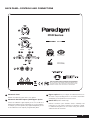
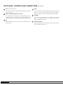
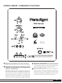
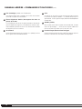
BACK PANEL: CONTROLS AND CONNECTIONS
PDR Series
CONTAINS FCC ID: WUO-WRX1010. THIS DEVICE COMPLIES WITH PART 15 OF THE FCC RULES. OPERATION IS
SUBJECT TO THE FOLLOWING TWO CONDITIONS: (1) THIS DEVICE MAY NOT CAUSE HARMFUL INTERFERENCE,
AND (2) THIS DEVICE MUST ACCEPT ANY INTERFERENCE RECEIVED, INCLUDING INTERFERENCE THAT MAY
CAUSE UNDESIRED OPERATION. CHANGES OR MODIFICATIONS NOT EXPRESSLY APPROVED BY THE PARTY
RESPONSIBLE FOR COMPLIANCE COULD VOID THE USER’S AUTHORITY TO OPERATE THE EQUIPMENT.
STANDBY
PAIRSTATUS
1
10
2
3
4 5
6
7
8
9
PRODUCT CONSUMES LESS
THAN 1 WATT IN STANDBY.
Manufactured Under License.
U.S. Patent # 5,075,634 and
5,510,753 Patent Pending
Subwoofer Level
Balances the subwoofer output level to your speakers.
Subwoofer Cut-Off Frequency with Bypass Option
Controls the subwoofer’s upper-frequency cut-off. This can be set to
match the low-frequency roll-off characteristics of your front speakers.
For example, if your front speakers play to approximately 80 Hz, you can
set the subwoofer cut-off frequency to approximately 80 Hz.
Bypass option allows you to bypass the subwoofer’s built-in cut-
off control to let your preamp/processor’s or receiver’s internal bass
management system provide the crossover function.
Status LED
(wireless models only)
Indicates connection status between wireless subwoofer and
transmitter (e.g. Not Paired, Searching for Connection, Paired).
For additional information see text section ‘Pairing Your Wireless
Subwoofer with the Transmitter.’
1
2
3
4

Pair
(wireless models only)
This feature initiates wireless pairing between your wireless subwoofer
and the transmitter.
Phase Alignment Switch (0 or 180°)
The sound from your subwoofer may arrive at the listening position out
of phase with the front speakers. This switch synchronizes the
subwoofer and the front speakers through their frequency overlap region.
On
When the toggle switch is in the ‘On’ position, your subwoofer remains
continuously on.
Auto
This mode eliminates the need to repeatedly switch your subwoofer on
and off — it will turn on when it receives an input signal. If no signal is
sensed for a period of time, it will automatically switch to standby.
Standby
In this mode your subwoofer remains on standby. This uses very little
power — the wired subwoofer uses less than 0.5 watts and the
wireless model less than 1 watt.
Line-Level Input
Allows connection from the Sub/LFE Output of an A/V receiver, processor
or other suitable low-level source.
6
8
9
10
5
7
BACK PANEL: CONTROLS AND CONNECTIONS
(continued)
5

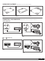
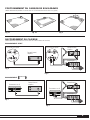
SUBWOOFER PLACEMENT
(Additional details in text section Subwoofer Placement)
CONNECTING YOUR SUBWOOFER
(Additional details in text section Connecting Your Subwoofer)
STANDBY
Sub Out
L
R
L
Right In
Sub/Left In
DC In +5v
+
-
L
+– +
LR
–
L
R
L
L
R
Speakers
STANDBY
L
+– +
LR
–
L
R
L
L
R
Speakers
Right In
Sub/Left In
Sub Out
DC In +5v
+
-
L
L
R
Fig. 1a
Fig. 1b Fig. 2
Fig. 3
Fig. 4
Fig. 5
Fig. 6
WIRELESS
CONNECTION
WIRED CONNECTION
Preamp / Receiver
Preamp / Receiver
Preamp / Receiver
Preamplifier
Wireless Transmitter
Wireless Transmitter
Power Amplifier
Power Amplifier
Subwoofer Subwoofer
6

IMPORTANT! Transmitter and subwoofer must be no more than 50’ (15 m) apart in the room
PDR Series
CONTAINS FCC ID: XXXXXXXXXXXXXX. THIS DEVICE COMPLIES WITH PART 15 OF THE FCC RULES. OPERATION IS
SUBJECT TO THE FOLLOWING TWO CONDITIONS: (1) THIS DEVICE MAY NOT CAUSE HARMFUL INTERFERENCE,
AND (2) THIS DEVICE MUST ACCEPT ANY INTERFERENCE RECEIVED, INCLUDING INTERFERENCE THAT MAY
CAUSE UNDESIRED OPERATION. CHANGES OR MODIFICATIONS NOT EXPRESSLY APPROVED BY THE PARTY
RESPONSIBLE FOR COMPLIANCE COULD VOID THE USER’S AUTHORITY TO OPERATE THE EQUIPMENT.
STANDBY
PAI RSTATUS
PRODUCT CONSUMES LESS
THAN 1 WATT I N STANDBY.
Manufactured Under License.
U.S. Patent # 5,075,634 and
5,510,753 Patent Pending
STANDBY
STATUS
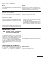
Step 1
Right In
Sub/Left In
DC In +5v
+
-
Step 2
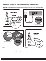
Transmitter front-Panel LED
Slow Blink = Not paired
Fast Blink = Searching for connection
Solid Glow = Paired (connection established between transmitter and subwoofer)
What do the blinking LEDs mean on Subwoofer and Transmitter?
‘PAIRING’ YOUR WIRELESS SUBWOOFER WITH THE TRANSMITTER
(Additional details in text section Pairing Your Wireless Subwoofer with the Transmitter)
is subject to the following two condition
and (2) This device must accept any i
cause undesired operation. Changes o
responsible for compliance could void t
© Parad
Press Here to Pair
Step 3
Bottom of Transmitter
PDR Series
CONTAINS FCC ID: XXXXXXXXXXXXXX. THIS DEVICE COMPLIES WITH PART 15 OF THE FCC RULES. OPERATION IS
SUBJECT TO THE FOLLOWING TWO CONDITIONS: (1) THIS DEVICE MAY NOT CAUSE HARMFUL INTERFERENCE,
AND (2) THIS DEVICE MUST ACCEPT ANY INTERFERENCE RECEIVED, INCLUDING INTERFERENCE THAT MAY
CAUSE UNDESIRED OPERATION. CHANGES OR MODIFICATIONS NOT EXPRESSLY APPROVED BY THE PARTY
RESPONSIBLE FOR COMPLIANCE COULD VOID THE USER’S AUTHORITY TO OPERATE THE EQUIPMENT.
STANDBY
PAI RSTATUS
PRODUCT CONSUMES LESS
THAN 1 WATT I N STANDBY.
Manufactured Under License.
U.S. Patent # 5,075,634 and
5,510,753 Patent Pending
PAIR
Step 4
7
Back Panel of Subwoofer

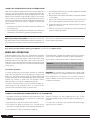
YOUR NEW SUBWOOFER
The ‘Watts’ (W) rating indicated on the back panel of your subwoofer is
the typical AC power the unit will consume when producing its
maximum power output. However, the actual wattage consumption will
vary with the bass content of the program material.
POWER REQUIREMENTS
Break-In
Although your Paradigm subwoofer will sound great ‘out of the carton’ it will
sound even better when broken in. Allow it to operate for several hours before
you listen critically.
Cleaning
Do not use a strong or abrasive cleaner on your subwoofer. Clean it with
a damp soft cloth, but do not get it wet. Do not place wet objects, such as
drinking glasses or potted plants, on top of it. If allowed to soak in, even
a small amount of water may permanently damage the enclosure.
You are about to experience the powerful and extremely accurate deep bass
performance of Paradigm subwoofers. They offer incredible output with low
distortion, exceptional extension and superb definition. It is important to
note, however, that just as the amount of soft furnishings has a decided
impact on mid and high frequencies, those frequencies below 150 Hz are
dramatically affected by the room itself—its size, shape, as well as the
physical boundaries of the room. The extra care you take in correctly
positioning your subwoofer(s) will result in greater listening enjoyment. Keep
the following guidelines in mind when deciding on best subwoofer placement:
• Concrete floors and walls tend to aggravate low-frequency standing
wave problems and are less preferred.
• Rooms where height, width and length are similar should be avoided as
they can exhibit significant low-frequency standing wave problems. This
may result in reduced clarity. If no other room is possible, experiment
with subwoofer placement to minimize acoustic problems.
ROOM ACOUSTICS
SUBWOOFER PLACEMENT
To avoid personal injury, install subwoofer in a location
where any rear amplifier parts such as panels and/or
heatsinks, etc. cannot be accidentally touched.
Bass is less and less directional as it goes down in frequency. For best sonic
integration, locating your subwoofer between your front speakers or beside
one of them and close to the back wall will usually provide the best bass
performance. If this location is not possible your subwoofer may be placed
anywhere in the room without affecting the stereo image of your front
speakers or the soundstage of your multichannel speaker system.
Fig. 1a and Fig. 1b highlight how bass output is generally affected by room
placement. When seated in a typical listening area of your room, placing the
subwoofer inside the ‘shaded’ areas will typically result in bass performance
as follows:
Fig. 1a
:
Corner placement provides the most bass, but sometimes at the
expense of accuracy.
Fig. 1b
:
A subwoofer placed near a wall usually provides a good balance of
quantity and accuracy.
Controls are provided to align your subwoofer’s output with that of the other
speakers in your system, see later section on ‘Fine Tuning.’
Although a single Paradigm subwoofer provides exceptional performance
and substantial output, the quality (and quantity) of bass can be further
improved with the use of two subwoofers (Fig. 2)
.
This allows you to
randomize the standing waves within your listening room so that bass will
be distributed in a more uniform manner. Two subwoofers also provide even
lower distortion, especially at high output levels.
Wireless Subwoofers
Keep in mind that when using two wireless PDR-W100 subwoofers, one
wireless transmitter is required per subwoofer.
(See Dealer for connection instructions using multiple subwoofers.)
THE ADVANTAGES OF USING TWO SUBWOOFERS
8

When using two subwoofers, placing one in the front of the room and the other
in the rear of the room (as shown in Fig. 2) usually provides the best bass
performance and sonic integration. Consult the fine tuning section of the Owner’s
Manual for more information on adjusting phase settings. If those locations
are not possible or if you want to experiment with placement options using two
subwoofers, the following procedure will be a helpful guide to achieving better
bass performance. Refer to the section on ‘Subwoofer Connection,’ then
proceed as follows:
1. Temporarily turn all speakers off (either by turning your amplifier off or
disconnecting them);
2. Connect and place one subwoofer in the central area of your listening room.
Follow directions for connection, as outlined in the appropriate section;
3. At a moderately loud level, play music or a video soundtrack with extended
bass that is repetitive or continuous;
4. Walk around your room and note where the bass sounds louder and where
it sounds quieter;
5. Place the first subwoofer within a louder bass area of your room; then
place the second subwoofer within a quieter bass area of your room;
6. Connect both subwoofers and switch all speakers back on; switch the
amplifier on, or reconnect it;
7. Follow the ‘Fine Tuning’ instructions later in this manual, to optimize your
system’s overall bass performance.
USING TWO SUBWOOFERS IN YOUR LISTENING ROOM
‘PAIRING’ YOUR WIRELESS SUBWOOFER WITH THE TRANSMITTER
WIRELESS OPERATION
NOTE: The preceding is only a guideline. You may want to use a bass test
disc and SPL meter to more accurately determine the bass characteristics of
your listening room
(see Dealer for more information)
. Remember that room
acoustics vary so it may take some experimenting with placement to achieve
the best subwoofer performance.
Subwoofer placement plays a major role in optimizing bass performance.
However, placement can impose the inconvenience, not to mention the
unsightliness, of running long lengths of cable through walls, along
baseboards and under floors and carpets. Going wireless means you no
longer have to worry about placement while cable clutter becomes a thing
of the past. Actual system setup time is often drastically reduced with the
wireless option.
Transmitter Operation
In a typical listening room your new wireless transmitter has a maximum
range of 50’ (15 m). Obstructions such as walls, large pieces of furniture, room
dividers, etc., may reduce transmitter range. Do not place subwoofer and
transmitter farther apart than the recommended range. We do not recommend
installing your transmitter in another room. The transmitter’s compact
dimensions allow it to fit neatly into a standard audio/video rack.
Your wireless transmitter features a 2.4 GHz uncompressed digital self-
sensing design that will automatically adjust for the best wireless
connection while monitoring the integrity of the data stream.
An RCA audio cable is required
(not included)
to connect the transmitter to
your A/V receiver or preamplifier.
(See Dealer for cable recommendations.)
One transmitter is required for each wireless subwoofer in operation.
WARNING: To prevent signal dropouts or interference, keep the
transmitter well out of range of a microwave oven, mobile telephone
or Bluetooth device operating on the same frequency.
IMPORTANT! The transmitter that is included with your wireless-ready
Paradigm PDR subwoofer is not compatible with any other subwoofer brand.
Before connecting your new subwoofer, you must establish a permanent
connection between the transmitter and subwoofer by ‘pairing’ the two.
See below for more details …
1. Plug subwoofer into wall
(not shown)
and using the toggle switch on the
back panel, turn it on (ON or AUTO setting). Wait for the back-panel
‘STATUS’ LED to flash Red slowly.
2. Plug transmitter into wall, the LED will also flash Red slowly.
3. Press and hold ‘Pair’ button on transmitter for 3 to 5 seconds until the
transmitter’s front-panel LED begins to flash Red quickly. Release button.
4. Press and release ‘Pair’ button on back panel of subwoofer.
Permanent connection has been established when LEDs on both
transmitter and subwoofer glow solid Red. Typically, the pairing process is
permanent.
If for some reason you do have to ‘pair’ transmitter and subwoofer again,
simply follow this 4-step process.
If you are are not using a wireless option on your subwoofer
(selected models only)
skip this section
9

SUBWOOFER CONNECTION
(all models)
SAFETY PRECAUTION: Before proceeding with this
section be sure to read and follow all safety precaution
and instruction notices at the beginning of this manual.
Turn all components OFF before connecting
the subwoofer.
We recommend the use of high-quality cables and connectors when hooking
up your subwoofer
(see Dealer for more information)
.
a) Line-Level Input From Sub/LFE Output (Fig. 3) – For use with a
receiver or processor that has a Sub-Out/ LFE-Out jack.
Using an RCA-to-RCA interconnect cable
(not included)
connect the
subwoofer as shown. If your subwoofer has two low-level input jacks
use the right (LFE) input.
b) Line-Level Input
From Pre-Out/Front-Out Without High-Pass
Output from Sub (Fig. 4) – For use with a processor/preamp and
amplifier, or receiver with Pre-Out/Front-Out and Main-In jacks.
Using RCA-to-RCA interconnect cables and ‘Y’ splitters
(not included)
connect the subwoofer as shown.
CONNECTION OPTIONS — Wired Subwoofer
CONNECTION OPTIONS — Wireless Subwoofer
a) Line-Level Input
From Sub/LFE Output (Fig. 5) – For use with a
receiver or processor that has a Sub-Out/LFE-Out jack.
Using an RCA-to-RCA interconnect cable
(not included)
connect the
transmitter as shown.
b) Line-Level Input
From Pre-Out/Front-Out Without High-Pass
Output from Sub (Fig. 6) – For use with a processor/preamp and
amplifier, or receiver with Pre-Out/Front-Out and Main-In jacks.
Using RCA-to-RCA interconnect cables and ‘Y’ splitters
(not included)
connect transmitter as shown.
FINE TUNING
Once you have the rest of your speakers positioned in the room and have
set speaker distances and calibrated speaker levels with your Processor
or A/V Receiver, it’s time for a little fine tuning of the subwoofer(s).
Subwoofer Controls
When setting the subwoofer controls use music and video soundtracks
that you know well. They should contain selections with extended bass
that is continuous and repetitive. When you are adjusting your subwoofer,
remember: Bass should not be overbearing—the subwoofer should not
draw attention to itself—but sound shouldn’t be ‘thin’ or difficult to hear.
Certain subwoofer placement may result in bass frequency cancellations—
this occurs when your front speakers and subwoofer are ‘out-of-phase’, in
other words, they work against each other through the crossover region.
This will result in bass being reduced. If bass sounds weak or dislocated
adjust the phase according to the instructions that apply to your subwoofer
in the setup procedures that follow.
Before connecting your wired subwoofer, please read this section
to determine which setup option best suits your needs.
(See Dealer
if you require additional information.)
Before connecting your wireless transmitter to receiver or preamp/
processor, ensure you have “paired” subwoofer and transmitter,
(refer back to previous section).
10

1. Turn the Subwoofer Level control completely counter-clockwise to
its minimum;
2. Turn the Subwoofer Cut-Off Frequency control to ’Bypass’;
3. Set the Phase Switch to 0°;
NOTE: When using receivers with Automatic Level and Crossover
setting systems such as Anthem’s ARC system, the Volume Level
should be set to ‘Detent’ (center), Phase should be set to ‘0’ and
Crossover set to ‘Bypass,’ then skip the next four steps.
4. While you listen to a selection in your primary listening area, have an
assistant turn up the Subwoofer Level control until the subwoofer
can be clearly heard;
5. Have your assistant try the Phase Control Switch in both positions
until you determine which one delivers the most bass. Your subwoofer
and front speakers are now ‘in phase.’ Do not change phase switch again
unless you move your subwoofer or front speakers;
6. Turn the Subwoofer Level control completely counter-clockwise to
its minimum;
7. Turn the Subwoofer Cut-Off Frequency control completely counter-
clockwise to 50 Hz;
8. Slowly rotate the Subwoofer Level control until you match the
subwoofer output level with the level of your front speakers. Bass
should be clearly audible, but not intrusive;
9. Slowly rotate the Subwoofer Cut-Off Frequency control until you
hear the best subwoofer/main speaker blend. If the sound is too ‘thin,’
you have not set the frequency high enough; if the sound becomes
‘boomy’ you have set the frequency too high. Adjust until you find the
most natural balance.
SETTING SUBWOOFER CONTROLS
11

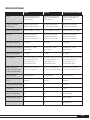
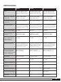
SPECIFICATIONS
PDR-80 PDR-100
Design
Amplifier: High-Current,
Discreet Ouput
Amplifier Design Features
Bass Driver
Low-Frequency Extension*
Subwoofer Cut-Off Frequency
Sub/Sat Phase Alignment
Line-Level Inputs
Height, Width, Depth
(height includes feet; depth
includes grille and amplifier)
Weight (unpacked)
Finish
RF Frequency (wireless model)
Latency (ms)
Transmission Range (ft/m)
Sampling Frequency /# bits
Compression
Single driver, bass reflex, high-
velocity low-turbulence port,
built-in amplifier
300 watts Dynamic Peak/
100 watts RMS Sustained
Auto-On/Standby, soft clipping
210-mm (8 in) reinforced
polymer-composite cone,
35.5-mm (1-1/2 in) voice-coil
32 Hz (DIN)
Variable 50 Hz – 150 Hz;
Bypass option
0° or 180°
Two RCA (L/R-Mono) for L/R line
out or Sub-Out/LFE-Out of
receiver/processor or
other line-level source
35.6 cm x 30.5 cm x 36.2 cm
14 in x 12 in x 14-6/16 in
10.9 kg/24 lb each
Black Ash
n/a
n/a
n/a
n/a
n/a
Single driver, bass reflex, high-
velocity low-turbulence port,
built-in amplifier
360 watts Dynamic Peak/
120 watts RMS Sustained
Auto-On/Standby, soft clipping
254-mm (10 in) reinforced
polymer-composite cone,
38-mm (1-1/2 in) voice coil
29 Hz (DIN)
Variable 50 Hz – 150 Hz;
Bypass option
0
°
or 180
°
Two RCA (L/R-Mono) for L/R line
out or Sub-Out/LFE-Out of
receiver/processor or
other line-level source
39.4 cm x 33.3 cm x 38.7 cm
15-1/2 in x 13-2/16 in x 15-1/4 in
13.2 kg/29 lb each
Black Ash
n/a
n/a
n/a
n/a
n/a
PDR-W100 (wireless model)
Single driver, bass reflex, high-
velocity low-turbulence port,
built-in amplifier
360 watts Dynamic Peak/
120 watts RMS Sustained
Auto-On/Standby, soft clipping
254-mm (10 in) reinforced
polymer-composite cone,
38-mm (1-1/2 in) voice coil
29 Hz (DIN)
Variable 50 Hz – 150 Hz;
Bypass option
0
°
or 180
°
Two RCA (L/R-Mono) for L/R line
out or Sub-Out/LFE-Out of
receiver/processor or
other line-level source
39.4 cm x 33.3 cm x 38.7 cm
15-1/2 in x 13-2/16 in x 15-1/4 in
13.2 kg/29 lb each
Black Ash
2.4 GHz
13 ms
15 meters (50 ft)
48 kHz, 16 bits
No compression
* DIN 45 500. Indicates -3 dB in a typical listening room.
12

LIMITED WARRANTY
Paradigm
®
subwoofers covered in this manual are warranted to be and
remain free of manufacturing and/or material defects for a period of
three (3) years from the date of the original retail purchase. For
subwoofers with a wireless option, the included transmitter is also
warranted to be and remain free of manufacturing/and or material
defects for a period of three (3) years from the date of the original
retail purchase.
Within the time period specified, repair, replacement or adjustment of parts
for manufacturing and/or material defects will be free of charge to the
original owner.
Thermal or mechanical abuse/misuse is not covered under warranty.
Limitations:
• Warranty begins on date of original retail purchase from an Authorized
Paradigm Dealer only. It is not transferable;
• Warranty applies to product in normal home use only. If the product is
subjected to any of the conditions outlined in the next section, warranty
is void;
• Warranty does not apply if the product is used in professional or
commercial applications.
Warranty is Void if:
• The product has been abused (intentionally or accidentally);
• The product has been used in conjunction with unsuitable or faulty
equipment;
• The product has been subjected to damaging signals, derangement in
transport, mechanical damage or any abnormal conditions;
• The product (including cabinet) has been tampered with or damaged by
an unauthorized service facility;
• The serial number has been removed or defaced.
Owner Responsibilities:
• Provide normal/reasonable operating care and maintenance;
• Provide or pay for transportation charges for product to service facility;
• Provide proof of purchase (your sales receipt given at time of purchase
from your Authorized Paradigm Dealer).
Should servicing be required, contact your nearest Authorized Paradigm
Dealer, Paradigm Electronics Inc., or Import Distributor (outside the U.S.
and Canada) to arrange, bring in or ship prepaid any defective unit. Visit
our website at www.paradigm.com for more information.
Paradigm Electronics Inc. reserves the right to improve the design of any
product without assuming any obligation to modify any product previously
manufactured.
This warranty is in lieu of all other warranties expressed or implied, of
merchantability, fitness for any particular purpose and may not be extended
or enlarged by anyone. In no event shall Paradigm Electronics Inc., their
agents, or representatives be responsible for any incidental or consequential
damages. Some jurisdictions do not allow limitation of incidental or
consequential damages, so this exclusion may not apply to you.
Retain this manual and your sales receipt for proof of warranty
term and proof of purchase.
13

Paradigm Electronics Inc. Au Canada : 205, boul. Annagem, Mississauga (Ontario) L5T 2V1. Aux É.-U. : MPO Box 2410, Niagara Falls, NY 14302
080410
Merci d’avoir choisi les caissons de sous-graves Paradigm PDR et
félicitations! Vous entendrez la différence que confèrent ces caissons de sous-
graves de pointe haut de gamme à votre système audio ou de cinéma maison.
Ces caissons de sous-graves sont le produit d'innombrables heures de recherche
et de développement approfondis et vous fourniront un son haut de gamme de
qualité supérieure pendant de nombreuses années.
Pour profiter pleinement de l’excellence sonore de ces caissons de sous-graves, il
importe d’apporter un soin particulier à leur installation et à leur utilisation. Veuillez
lire le présent manuel et suivre toutes les instructions. Si vous avez des questions
à poser, veuillez communiquer avec votre revendeur Paradigm autorisé ou consulter
la page de questions et réponses de notre site Web : www.paradigm.com.
MD
LE SUMMUM EN QUALITÉ SONORE POUR LA MUSIQUE ET LE CINÉMA MAISON
MC
SANS FIL
CAISSON DE SOUS-GRAVES DE LA SÉRIE PDR
MODE D’EMPLOI
Comprend
un modèle

Mesures de sécurité . . . . . . . . . . 2
Consignes de sécurité
importantes . . . . . . . . . . . . . . . . . 3
Panneau arrière : commandes et
raccords (illustration) . . . . . . . . . . 4
Positionnement du caisson de
sous-graves (illustration) . . . . . . . 6
Raccorder du caisson
(illustration) . . . . . . . . . . . . . . . . . . 6
Jumeler le caisson de sous-graves
au transmetteur (illustration) . . . 7
Votre nouveau caisson
de sous-graves . . . . . . . . . . . . . . . 8
Alimentation . . . . . . . . . . . . . . . . . 8
Salle d’écoute . . . . . . . . . . . . . . . . 8
Positionnement du caisson
de sous-graves . . . . . . . . . . . . . . . 8
Fonctionnement sans fil . . . . . . . 9
Raccordement du caisson
de sous-graves . . . . . . . . . . . . . . .10
Réglage fin . . . . . . . . . . . . . . . . . . .10
Spécifications . . . . . . . . . . . . . . . .12
Garantie limitée . . . . . . . . . . . . . .13
TABLE DES MATIÈRES
DIRECTIVES EUROPEENNES SUR LE RECYCLAGE ET LE TRAITEMENT DES DECHETS
Dans le respect de la directive WEEE (Waste Electrical & Electronic Equipment) mise en place par les institutions
Européennes à compter du 13 Août 2005, nous souhaitons vous informer que ce produit peut contenir des matières
devant faire l’objet d’une procédure de recyclage ou de traitement approprié des déchets. Dans cette optique,
Paradigm Electronics Inc (fabricant des enceintes Paradigm et des électroniques Anthem) avec ses Distributeurs
agréés dans l’Union Européenne, ont mis en place une procédure de collecte et de retraitement gratuite. Pour en
savoir davantage sur cette procédure veuillez contacter votre revendeur, ou notre Distributeur dans votre pays (vous
en obtiendrez les coordonnées sur simple demande ou en consultant notre site internet www.paradigm.com).
Notez que seul le produit fini est concerné par cette directive et ses obligations. S’agissant de son emballage et
de ses accessoires de transport nous vous recommandons de les recycler selon les procédures mises en place par
votre commune ou votre département.
© Paradigm Electronics, Inc. Tous droits réservés. www.paradigm.com
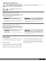
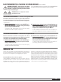
INSTRUCTIONS POUR LE JUMELAGE (PAIRING) SANS FIL
1. Branchez le caisson de sous-graves dans le mur et allumez-le
(On ou Auto) à l’aide de l’interrupteur à bascule du panneau
arrière. Attendez que la DEL du panneau arrière clignote
en rouge lentement
2. Branchez le transmetteur dans le mur. Sa DEL clignotera en rouge
lentement.
3. Appuyez et maintenez enfoncé le bouton « Pair » (jumelage) du
transmetteur jusqu’à ce que la DEL commence à clignoter en rouge
rapidement. Relâchez le bouton.
4. Appuyez et relâchez le bouton « Pair » (jumelage) sur le panneau
arrière du caisson de sous-graves.
La connexion permanente est établie une fois que les deux DEL
restent allumées en rouge.
FCC ID: WU0-WRX1010. Cet appareil est conforme à la partie 15 du
règlement FCC. Le fonctionnement est assujetti aux deux conditions
suivantes : (1) cet appareil ne peut pas causer d’interférence nuisible, et
(2) cet appareil doit accepter toute interférence reçue, notamment
l’information qui peut entraîner un fonctionnement indésirable. Les
changements ou les modifications qui ne sont pas expressément
approuvés par la partie responsable de la conformité pourraient
annuler l’autorité de l’utilisateur à utiliser l’équipement.
Appuyez ici pour jumeler

MESURES DE SÉCURITÉ
LIRE ATTENTIVEMENT CETTE SECTION AVANT DE POURSUIVRE!
AVERTISSEMENT : POUR DIMINUER LES RISQUES D’INCENDIE OU
DE CHOC ÉLECTRIQUE, N’EXPOSEZ PAS CET APPAREIL À LA PLUIE OU
À L’HUMIDITÉ; LES OBJETS REMPLIS DE LIQUIDE, TELS QUE LES
VASES, NE DOIVENT PAS ÊTRE PLACÉS SUR L’APPAREIL.
MISE EN GARDE : POUR ÉVITER UN CHOC ÉLECTRIQUE,
PLACER LA BROCHE LARGE DE LA FICHE EN CORRESPONDANCE
AVEC L'ALVÉOLE LARGE, ET INSÉRER COMPLÈTEMENT LA FICHE.
MISE EN GARDE : POUR MAINTENIR UNE PROTECTION CONTINUE
CONTRE LES RISQUES D'INCENDIE, REMPLACER LE FUSIBLE
UNIQUEMENT PAR UN FUSIBLE DE MÊMES CARACTÉRISTIQUES
(INTENSITÉ ET TENSION). CONFIER LE REMPLACEMENT À UN
PERSONNEL QUALIFIÉ.
AVERTISSEMENT : LA TEMPÉRATURE DE L'APPAREIL PEUT
AUGMENTER. VEILLER À TOUJOURS MÉNAGER UNE VENTILATION
ADÉQUATE PERMETTANT LE REFROIDISSEMENT. NE PAS PLACER
L'APPAREIL À PROXIMITÉ D'UNE SOURCE DE CHALEUR, OU DANS
UN ESPACE OÙ LA VENTILATION EST RESTREINTE.
AVERTISSEMENT : POUR MINIMISER LE RISQUE DE CHOC
ÉLECTRIQUE, NE PAS ÔTER LE CAPOT (OU LE PANNEAU
ARRIÈRE). IL N’Y A À L’INTÉRIEUR AUCUN COMPOSANT
RÉPARABLE PAR L’UTILISATEUR. CONFIER TOUTE INTERVENTION
À UN PERSONNEL QUALIFIÉ.
L’éclair avec une pointe en forme de flèche dans un
triangle équilatéral avertit l’utilisateur d’une
« tension dangereuse » non isolée à l’intérieur du
produit qui peut être d’une force suffisante pour
constituer un risque de décharge électrique.
Le point d’exclamation dans un triangle équilatéral
avertit l’utilisateur de la présence de directives
importantes en lien avec le fonctionnement et la
maintenance (service) dans les documents qui
accompagnent le produit.
AVERTISSEMENT
RISQUE DE CHOC
ÉLECTRIQUE – NE PAS OUVRIR.
2

CONSIGNES DE SÉCURITÉ IMPORTANTES
1) Lire les instructions.
2) Conserver les instructions.
3) Respecter les avertissements.
4) Suivre toutes les instructions.
5) Ne pas utiliser ce produit à proximité d’eau.
6) Nettoyer avec un linge sec uniquement.
7) Ne pas bloquer les ouvertures d’aération. Effectuer l’installation
conformément aux instructions du fabricant.
8) Ne pas installer près d’une source de chaleur – radiateur, bouche
de chaleur, réchaud/cuisinière ou autres appareils (y compris les
amplificateurs) qui produisent de la chaleur.
9) Ne pas circonvenir la caractéristique de sécurité de la fiche de
branchement polarisée. Une fiche polarisée a deux lames, et une
des lames est plus grande que l’autre. Une fiche de type mise à la
terre a deux lames et une broche de mise à la terre. La lame large
ou la troisième broche sont fournies pour votre sécurité. Si la fiche
fournie ne s’insère pas dans la prise, consulter un électricien pour le
remplacement de la prise obsolète.
10) Protéger le cordon d’alimentation de manière à ce que personne ne
marche dessus et à ce qu’il ne soit pas coincé, particulièrement au
niveau des fiches et des prises auxiliaires, et à l’endroit où le cordon
d’alimentation sort du produit.
11) Utiliser uniquement les accessoires recommandés par le
fabricant.
12) Utiliser ce produit uniquement avec un dispositif de
support (chariot, pied, trépied, support ou table)
recommandé par le fabricant ou vendu avec le produit.
Lorsqu’un chariot est utilisé, déplacer prudemment le
montage chariot/appareil pour éviter les blessures
liées au basculement.
13) Débrancher cet appareil pendant les orages ou s’il n’est pas utilisé
pendant une longue période.
14) Confier tout travail d’entretien à une personne compétente.
L’entretien est nécessaire lorsque l’appareil a été endommagé de
quelque façon que ce soit : dommages au cordon d’alimentation ou
à la fiche, chute d’un liquide ou d’un objet dans l’appareil, exposition
de l’appareil à la pluie ou à l’humidité, fonctionnement anormal ou
chute de l’appareil.
15) NE PAS EXPOSER CET ÉQUIPEMENT AUX ÉCOULEMENTS OU AUX
ÉCLABOUSSURES, ET S’ASSURER QU’AUCUN OBJET REMPLI
D’EAU, TEL QU’UN VASE, N’EST PLACÉ SUR L’APPAREIL.
16) POUR DÉBRANCHER COMPLÈTEMENT CET APPAREIL DE LA
SOURCE D’ALIMENTATION C.A., DÉBRANCHER LA FICHE DU
CORDON D’ALIMENTATION DE LA PRISE C.A..
17) LA FICHE PRINCIPALE DU CORDON D’ALIMENTATION DOIT RESTER
À PORTÉE DE MAIN.
3

4
PANNEAU ARRIÈRE : COMMANDES ET RACCORDS
PDR Series
CONTAINS FCC ID: WUO-WRX1010. THIS DEVICE COMPLIES WITH PART 15 OF THE FCC RULES. OPERATION IS
SUBJECT TO THE FOLLOWING TWO CONDITIONS: (1) THIS DEVICE MAY NOT CAUSE HARMFUL INTERFERENCE,
AND (2) THIS DEVICE MUST ACCEPT ANY INTERFERENCE RECEIVED, INCLUDING INTERFERENCE THAT MAY
CAUSE UNDESIRED OPERATION. CHANGES OR MODIFICATIONS NOT EXPRESSLY APPROVED BY THE PARTY
RESPONSIBLE FOR COMPLIANCE COULD VOID THE USER’S AUTHORITY TO OPERATE THE EQUIPMENT.
STANDBY
PAIRSTATUS
1
10
2
3
4 5
6
7
8
9
PRODUCT CONSUMES LESS
THAN 1 WATT IN STANDBY.
Manufactured Under License.
U.S. Patent # 5,075,634 and
5,510,753 Patent Pending
Subwoofer Level (Niveau caisson de sous-graves)
Équilibre le niveau de sortie du caisson de sous-graves vers vos enceintes.
Subwoofer Cut-Off Frequency with Bypass Option
(Fréquence de coupure du caisson de sous-graves avec
option de contournement)
Commande la fréquence de coupure supérieure du caisson de sous-
graves. Elle peut être réglée pour correspondre aux caractéristiques
Peut être réglée en fonction des caractéristiques d’atténuation des
graves des enceintes avant. Par exemple, si les enceintes avant
reproduisent les fréquences jusqu’à 80 Hz environ, la fréquence de
coupure du caisson de sous-graves peut être réglée à environ 80 Hz.
L’option de contournement vous permet de contourner la
commande de coupure intégrée du caisson de sous-graves afin de permettre
au système de gestion des graves interne de votre préamplificateur/
processeur ou récepteur de fournir la fonction de raccord
Status LED (DEL de statut)
(modèles sans fil uniquement)
Indique le statut de la connexion entre le caisson de sous-graves sans fil
et le transmetteur (p. ex. : non jumelés, recherche de connexion, jumelés).
Pour obtenir des renseignements supplémentaires, consultez la section
« Jumeler le caisson de sous-graves sans fil au transmetteur ».
1
2
3
4

Pair (Jumelage)
(modèles sans fil uniquement)
Cette caractéristique lance le jumelage sans fil entre votre nouveau
caisson de sous-graves et le transmetteur.
Phase Alignment Switch (Interrupteur de mise en
phase) (0 ou 180°)
Le son produit par le caisson de sous-graves parvenant à l’aire d’écoute
peut être déphasé par rapport au son émanant des enceintes avant.
Cette commande synchronise le caisson et les enceintes dans la bande
de fréquences qu’ils ont en commun.
On (Allumé)
Lorsque l’interrupteur à bascule est en position « On » (allumé), le caisson
de sous-graves reste continuellement allumé.
Auto
Ce mode fait en sorte qu’il n’est plus nécessaire de fermer et d’ouvrir
le caisson de sous-graves à répétition — il s’allumera lorsqu’il reçoit un
signal d’entrée. Si aucun signal n’est capté, il basculera automatiquement
en mode veille.
Standby (Veille)
Dans ce mode, le caisson de sous-graves reste en mode veille. Ce mode
utilise très peu d’énergie — le caisson de sous-graves câblé utilise
moins de 0,5 watt et le modèle sans fil, moins de 1 watt.
Line-level Input (Entrée niveau de ligne)
Permet le raccord à partir de la sortie Sub/LFE d’un récepteur A/V, d’un
processeur ou de toute autre source de bas niveau appropriée.
6
7
8
9
10
5
PANNEAU ARRIÈRE : COMMANDES ET RACCORDS
(suite)
5
La page charge ...
La page charge ...
La page charge ...
La page charge ...
La page charge ...
La page charge ...
La page charge ...
La page charge ...
La page charge ...
-
 1
1
-
 2
2
-
 3
3
-
 4
4
-
 5
5
-
 6
6
-
 7
7
-
 8
8
-
 9
9
-
 10
10
-
 11
11
-
 12
12
-
 13
13
-
 14
14
-
 15
15
-
 16
16
-
 17
17
-
 18
18
-
 19
19
-
 20
20
-
 21
21
-
 22
22
-
 23
23
-
 24
24
-
 25
25
-
 26
26
-
 27
27
-
 28
28
-
 29
29


Paradigm PDR 100 Le manuel du propriétaire
- Catégorie
- Équipement musical supplémentaire
- Taper
- Le manuel du propriétaire
dans d''autres langues
- English: Paradigm PDR 100 Owner's manual
Documents connexes
-
Paradigm Cinema Sub Manuel utilisateur
-
Paradigm Defiance V12 Manuel utilisateur
-
Paradigm Monitor SUB 12 Le manuel du propriétaire
-
Paradigm Defiance X15 Manuel utilisateur
-
Paradigm PW Soundbar Manuel utilisateur
-
-
-
Paradigm Soundtrack 2 Manuel utilisateur
-
-
Autres documents
-
Acoustic Research ARPR808 Manuel utilisateur
-
JBL SUB80P Wireless Powered Subwoofer Le manuel du propriétaire
-
Episode MEGA ES-SUB-MEGA-S15 Le manuel du propriétaire
-
 Amphony 1600 Manuel utilisateur
-
 Amphony 1600 Guide d'installation
-
Armacost Wireless Light Switch Remote Manuel utilisateur
-
Genelec 8030 and 7050 Stereo System Guide d'installation rapide
-
Elipson Planet SUB Blanc Le manuel du propriétaire

