Maytag MAH22PDAGW0 Guide d'installation
- Catégorie
- Machines à laver
- Taper
- Guide d'installation
Ce manuel convient également à

INSTALLATIONINSTRUCTIONS
COMMERCIALAUTOMATICWASHER
INSTRUCTIONSD'INSTALLATION
LAVE.LINGECOMMERCIALAUTOMATIQUE
Table of Contents/Table des matieres ................................ 2
Model/ModUle
MAH22PDAGW0, MAH22PNAGW0
W10215505A
www.maytagcommerciallaundry.com

TABLEOFCONTENTS
WASHER SAFETY .......................................................................... 2
INSTALLATION REQUIREMENTS ................................................ 3
Tools and Parts ............................................................................ 3
Options ......................................................................................... 4
Location Requirements ................................................................ 4
Drain System ................................................................................ 4
Electrical Requirements ............................................................... 5
Power Cord Installation................................................................ 5
INSTALLATION INSTRUCTIONS .................................................. 6
Remove Transport System .......................................................... 6
Connect the Inlet Hoses ............................................................... 6
Route the Drain Hose ................................................................... 7
Secure the Drain Hose ................................................................. 8
Level the Washer .......................................................................... 8
Payment System Setup ............................................................... 8
Complete Installation ................................................................... 8
USER & SETUP INSTRUCTIONS .................................................. 9
General Information ...................................................................... 9
Control Setup Procedures ........................................................... 9
Start Operating Setup ................................................................ 10
Washer Diagnostic Mode ........................................................... 13
WASHER CARE ............................................................................ 14
Cleaning Your Washer ............................................................... 14
Water Inlet Hoses ....................................................................... 15
ASSISTANCE OR SERVICE ......................................................... 15
Accessories ................................................................................ 15
WAR RANTY .................................................................................. 16
TABLEDESMATIERES
SECURITE DU LAVE-LINGE ........................................................ 17
EXIGENCES D'INSTALLATION ................................................... 18
Outillage et pieces ...................................................................... 18
Options ....................................................................................... 18
Exigences d'emplacement ......................................................... 19
Systeme de vidange ................................................................... 20
Specifications electriques .......................................................... 20
Installation du cordon d'alimentation ......................................... 21
INSTRUCTIONS D'INSTALLATION ............................................. 22
Depose du systeme de transport............................................... 22
Raccordement des tuyaux d'arrivee d'eau ................................ 22
Acheminement du tuyau de vidange ......................................... 23
Immobilisation du tuyau de vidange .......................................... 24
Reglage de I'aplomb du lave-linge ............................................ 24
Reglage du systeme de paiement ............................................. 24
Achever I'installation .................................................................. 24
INSTRUCTIONS D'UTILISATION ET D'INSTALLATION ...........25
Informations gen6rales ............................................................... 25
Procedures de reglage des systemes de commande ............... 25
Parametrage pour mise en marche ........................................... 26
Mode de diagnostic du lave-linge .............................................. 29
ENTRETIEN DU LAVE-LINGE ..................................................... 30
Nettoyage du lave-linge ............................................................. 30
Tuyaux d'arrivee d'eau ............................................................... 31
ASSISTANCE OU SERVICE ......................................................... 31
Accessoires ................................................................................ 31
GARANTIE ..................................................................................... 32
WASHER SAFETY
Your safety and the safety of others are very important.
We have provided many important safety messages in this manual and on your appliance. Always read and obey all safety
messages.
This is the safety alert symbol.
This symbol alerts you to potential hazards that can kill or hurt you and others.
All safety messages will follow the safety alert symbol and either the word "DANGER" or "WARNING."
These words mean:
You can be killed or seriously injured if you don't immediately
follow instructions.
You can be killed or seriously injured if you don't follow
instructions.
All safety messages will tell you what the potential hazard is, tell you how to reduce the chance of injury, and tell you what can
happen if the instructions are not followed.
2

iMPORTANT SAFETY iNSTRUCTiONS
WARNING: To reduce the risk of fire, electric shock, or injuryto persons when using the washer, folow basic precautions,
including the folowing:
[]
Under certain conditions, hydrogen gas may be
produced in a hot water system that has not been used
for 2 weeks or more. HYDROGEN GAS IS
EXPLOSIVE. If the hot water system has not been
used for such a period, before using the washing
machine, turn on all hot water faucets and let the water
flow from each for several minutes. This wil release
any accumulated hydrogen gas. As the gas is
flammable, do not smoke or use an open flame during
this time.
[] Before the washer is removed from service or discarded,
remove the door or lid.
[] Do not install or store the washer where itwill be exposed to
the weather.
[] Do not repair or replace any part of the washer or attempt any
servicing unless specificaly recommended in this manual or in
published user=repair instructions that you understand and
have the skills to carry out.
[] See "Electrical Requirements" for earthing instructions.
SAVE THESE iNSTRUCTiONS
INSTALLATIONREQUIREMENTS
Parts supplied for PD Models:
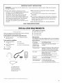
Gather the required tools and parts before starting installation.
The parts supplied are in the washer drum.
Tools needed for connecting the water inlet hoses
• Pliers (that open to • Flashlight (optional)
39.5 mm [1 9/16"])
Tools needed for installation
• Open end wrenches
1/2"and 9/16"
• Torx®t T-20 Security
screwdriver
• 1¼.nut driver
• Level
• Wood block
• Ruler or measuring tape
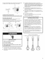
Parts supplied
A B
E
D
• Service door lock cam
• Coin sensor white
• Coin sensor black
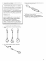
Alternate Parts
Your installation may require additional parts. Ifyou are interested
in purchasing one of the items listed here contact your authorized
Maytag distributor.
If You Have You Will Need to Buy
Laundry tub or Sump pump system (if not already
standpipe taller available)
than 2.4 m (96")
Overhead sewer Standard 76 L (20 gal. ), 762 mm (30") tall
drain tub or utility sink and sump pump
(available from local plumbing suppliers)
Floor drain Siphon break, Part Number 285834;
additional drain hose,
Part Number 8318155; and connector
kit, Part Number 285835
Drain hose 1.2 m (4 ft) drain hose extension kit,
too short Part Number 285863
Water taps beyond 2 longer water fill hoses:
reach of fill hoses 1.8 m (6 ft) Part Number 76314
3.0 m (10 ft) Part Number 350008
A. U-shaped hose form
B. Water inlet hoses (2)
C. Inlet hose washers (4)
D. Transit bolt hole plug (4)
E. Beaded tie strap
t® TORX is a registered trademark of Acument Intellectual Properties, LLC.

Pedestal
You have the option of purchasing pedestals separately for this
washer. The pedestal will add to the total height of the washer.
Optional pedestal
Pedestal Approximate Color Model
Height height Number
with washer
(73 mm) 2 ds" (1207 mm) 47.5" White WHP040
Selecting the proper location for your washer improves
performance and minimizes noise and possible washer "walk."
Your washer can be installed under a custom counter, or in a
basement, laundry room, or recessed area. See "Drain System."
Companion appliance location requirements should also be
considered. Proper installation is your responsibility.
You will need
A water heater set to deliver 60°C (140°F) water to the
washer.
An earthed electrical outlet located within 1.8 m (6 ft) of
where the power cord is attached to the back of the washer.
See "Electrical Requirements."
• Hot and cold water taps located within 1.2 m (4 ft)
of the hot and cold water fill valves, and water pressure
of 137.9-689.6 kPa (20-100 psi).
• A level floor with a maximum slope of 25 mm (1") under entire
washer. Installing the washer on soft floor surfaces, such as
carpets or surfaces with foam backing, is not recommended.
• A sturdy and solid floor to support the washer with a total
weight (water and load) of 180 kg (400 Ibs).
Do not operate your washer in temperatures below 0°C (32°F).
Some water can remain in the washer and can cause damage
in low temperatures.
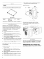
Installation clearances
• The location must be large enough to allow the washer door
to be fully opened.
• Additional spacing should be considered for ease of
installation and servicing. The door opens more than 90°
and it is not reversible.
• Additional clearances might be required for wall, door, and
floor moldings.
• Additional spacing of 25 mm (1") on all sides of the washer
is recommended to reduce noise transfer.
Companion appliance spacing should also be considered.
• When installed, the mains plug should be accessible for
washer disconnection from the mains supply.
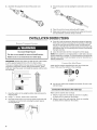
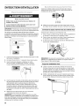
Washer Dimensions
686 mm
1282 (27")
134mm
(445/s'')
/
/
732mm
(2813/16")
Door is not reversible.
A floor drain should be provided under the bulkhead.
Prefabricated bulkheads with electrical outlets, water
inlet lines, and drain facilities should be used only where
local codes permit.
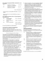
The washer can be installed using the standpipe drain system
(floor or wall), the laundry tub drain system, or the floor drain
system. Select the drain hose installation method you need.
See "Tools and Parts."
Standpipe drain system - wall or floor (views A & B)
The standpipe drain requires a minimum diameter standpipe of
50 mm (2"). The minimum carry-away capacity can be no less
than 64 L (17 gal.) per minute.
4

The top of the standpipe must be at least 762 mm (30") high and
no higher than 2.4 m (96") from the bottom of the washer.
B
Laundry tub drain system (view C)
The laundry tub needs a minimum 76 L (20 gal.) capacity. The top
of the laundry tub must be at least 762 mm (30") above the floor.
Floor drain system (view D)
The floor drain system requires a siphon break that may be
purchased separately. See "Tools and Parts."
The siphon break must be a minimum of 710 mm (28") from the
bottom of the washer. Additional hoses might be needed.
C D
Electric Shock Hazard
Plug into an earthed socket outlet.
Do not use an adapter,
Do not use an extension cord,
Failure to follow these instructions can result in death,
fire, or electric shock.
• A 220-240V, 50 Hz., fused electrical supply is required. A
time-delay 10-16A fuse or circuit breaker is recommended.
• This washer is equipped with a power supply cord having an
earthed plug.
• To minimize possible shock hazard, the cord must be
plugged into an earthed socket outlet, earthed in accordance
with local codes and ordinances. If a mating outlet is not
available, it is the personal responsibility and obligation of the
customer to have the properly earthed outlet installed by a
qualified electrician.
• If codes permit and a separate earth wire is used, it is
recommended that a qualified electrician determine that the
earth path is adequate.
• If the supply cord is damaged, it must be replaced by the
manufacturer, its service agent, or a qualified person to avoid
a hazard.
• Do not earth to a gas pipe.
• Check with a qualified electrician if you are not sure the
washer is properly earthed.
• Do not have a fuse in the neutral or earth circuit.
EARTHING iNSTRUCTiONS
This washer must be earthed. In the event of a malfunction
or breakdown, earthing will reduce the risk of electric
shock by providing a path of least resistance for electric
current. This washer is equipped with a cord having an
equipment-earthing conductor and an earthing plug. The
plug must be plugged into an appropriate outlet that is
properly installed and earthed in accordance with all local
codes and ordinances.
WARNING: Improper connection of the equipment-
earthing conductor can result in a risk of electric shock.
Check with a qualified electrician or serviceman if you are in
doubt as to whether the appliance is properly earthed.
Do not modify the plug provided with the appliance - if it
will not fit the outlet, have a proper outlet installed by a
qualified electrician.
1=
Select the plug that fits with the electric receptacle.
(

2.
Assemble the plug into the end of the power cord. 3. Secure the power cord by seating the connection on the cord
lock.
4. Place the cord lock cover and push until it snaps.
5. Make sure the power cord connection is seated on the cord
lock and that the cord lock clamps correctly.
INSTALLATIONINSTRUCTIONS
Excessive Weight Hazard
Use two or more people to move and install washer.
Failure to do so can result in back or other injury.
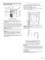
IMPORTANT: Position the washer so that the rear of the washer
is within approximately 900 mm (3ft) of its final location.
There are 4 shipping bolts in the rear panel of the washer that
support the suspension system during transportation. These
bolts also retain the power cord inside the washer until the bolts
are removed.
1.
2.
3.
[
Keep the washer in the upright position while removing the
shipping bolts.
Using a 1/2"wrench, loosen each of the bolts.
Once the bolt is loose, move it to the center of the hole and
completely pull out the bolt, including the plastic spacer
covering the bolt.
4. Once all 4 bolts are removed, discard the bolts and spacers.
Then push the power cord plug into the opening on the right
side of the rear panel and pull the power cord through the
opening on the left side of the rear panel and close holes with
the attached cap. Do not pull plug end of power cord through
the right side hole.
5. Close the bolt holes with the 4 transport bolt hole plugs.
NOTE: If the washer is to be transported at a later date, call your
product distributor or installer. To avoid suspension and structural
damage, your washer must be properly set up for relocation by a
trained professional.
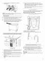
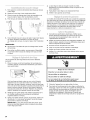
Insert new flat washers (supplied) into each end of the inlet
hoses. Firmly seat the washers in the couplings.
A B
A.Coupling
B.Washer
• Use the new inlet hoses supplied with washer. Do not re-use
old inlet hoses.
Connect the inlet hoses to the water taps
Make sure the washer drum is empty.
1. Attach a hose to the hot water tap. Screw on coupling
by hand until it is seated on the washer.
2. Attach a hose to the cold water tap. Screw on coupling
by hand until it is seated on the washer.
6

3. Using pliers, tighten the couplings with an additional
two-thirds turn.
NOTE: Do not overtighten or use tape or sealants on the tap.
Damage to the inlet hoses can result.
Clear water lines
• Run water through both taps and inlet hoses, into a laundry
tub, drainpipe, or bucket, to get rid of particles
in the water lines that might clog the inlet valve screens.
• Check the temperature of the water to make sure that the hot
water hose is connected to the hot water tap and that the
cold water hose is connected to the cold water tap.
4=
Turn on the water taps completely and check for leaks.
NOTE: Replace inlet hoses after 5 years of use to reduce the
risk of hose failure. Record hose installation or replacement
dates on the hoses for future reference.
Periodically inspect and replace hoses if bulges, kinks, cuts,
wear, or leaks are found.
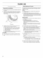
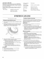
Proper routing of the drain hose protects your floor from damage
due to water leakage. Read and follow these instructions.
Remove drain hose from the washer
Gently pull the corrugated drain hose from the shipping clips.
Connect the inlet hoses to the check valves on washer
(1
H. Hot water inlet
C. Cold water inlet
1. Attach the hot water hose to the check valve on washer's hot
(H) water inlet valve. Screw on coupling by hand until it is
seated on the check valve.
2. Attach the cold water hose to the check valve on washer's
cold (C) water inlet valve. Screw on coupling by hand until it is
seated on the check valve.
3. Using pliers, tighten the couplings with an additional two-
thirds turn.
NOTE: Do not overtighten. Damage to the coupling can
result.
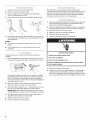
Laundry tub drain or standpipe drain
Connect the drain hose form to the corrugated drain hose.
A B
A. Snap either end of the drain hose form to the drain hose
at the point where the corrugation begins.
B. Bend drain hose over drain hose form and snap into place.
To keep drain water from going back into the washer:
• Do not straighten the drain hose, do not force excess drain
hose into standpipe. Hose should be secure, but loose
enough to provide a gap for air.
• Do not lay excess hose on the bottom of the laundry tub.
Floor drain
You may need additional parts. See Floor drain under "Tools and
Parts."

1. Drapethepowercordoverthewashertop.
2. Movethewashertoitsfinallocation.
3. Placethedrainhoseinthelaundrytuborstandpipeas
shown.SeeillustrationsAandB.
4. Securethedrainhoseusingthesuppliedbeadedtiestrap.
A B C
5. If the washer taps and the drain standpipe are recessed, put
the hooked end of the drain hose in the standpipe as shown.
See illustration C.
NOTES:
• Do not force excess drain hose back into the rear of the
washer.
• To avoid siphoning, do not seal the drain hose into the
standpipe.
Properly leveling your washer avoids excessive noise and
vibration.
1. Check the levelness of the washer by placing a level on the
top edge of the washer, first side to side, then front to back.
If the washer is against a wall, move the washer out slightly
before tipping back. If the washer is not level, first prop the
front with a wood block and adjust the feet as necessary;
then prop the back and adjust feet as necessary. Repeat this
step until washer is level.
2. Make sure all four feet are stable and resting on the floor.
Then check that the washer is level (use a level).
3. After the washer is level, use a 9/_6"open-end wrench to turn
the nuts on the feet tightly against the washer cabinet.
IMPORTANT: All four feet must be tightened. If the nuts are
not tight against the washer cabinet, the washer may vibrate.
4. The washer should not move front to back, side to side, or
diagonally when pushed on its top edges.
5. Slide the washer to its final location.
6. Confirm the levelness of the washer.
PD Model Washer is coin payment ready and allows the
connection of two different sizes of coins. Inside the drum is two
coin-sensor harnesses. To setup the washer for coin payment,
acquire a coin drop mechanism. Connect the white and black
coin sensors to the coin slot 1 and 2, respectively.
1. Check the electrical requirements. Be sure that you have the
correct electrical supply and the recommended earthing
method. See "Electrical Requirements."
2. Check that all parts are now installed. If there is an extra part,
go back through the steps to see which step was skipped.
3. Check that you have all of your tools.
4. Dispose of/recycle all packaging materials.
5. Check that the water taps are on.
6. Check for leaks around taps and inlet hoses.
Electric Shock Hazard
Plug into an earthed socket outlet.
Do not use an adapter.
Do not use an extension cord.
Failure to follow these instructions can result in death,
fire, or electric shock.
7.
8.
Plug into an earthed socket outlet.
To test and to clean your washer, measure _/2the detergent
manufacturer's recommended amount for a medium-size
load. Pour the detergent into the detergent dispenser. Select
any cycle and allow the washer to complete one whole cycle.
8

USER&SETUPINSTRUCTIONS
PERM. WOOLENS DELICATES
1. Door must be closed before cycle selection is made.
2. Press fabric setting keypad for the wash cycle desired. After
the cycle is started, the time will display and count down.
.... INOPERATIVE STATE - These lines on the display indicate
the washer is inoperative. Enter setup mode to view diagnostic
code.
"0 MINUTES" SHOWING IN DISPLAY - This condition indicates
the washer cannot be operated. Coins dropped during this
condition will be stored in escrow but cannot be used until
normal operation is restored by opening and closing the door. If a
door switch fails, it must be replaced before normal operation
can be restored.
COLD START (Initial first use) - Washer is programmed at the
factory as follows:
Washer 14-minute wash period
3 rinses (extra rinse not enabled)
7 x coin 1 wash price
WARM START (after power failure) - A few seconds after power
is restored, if a cycle was in progress at the time of the power
failure, "RESELECT CYCLE" will flash in the display, indicating
the need for a key press to restart washer.
DOOR LOCK - Prior to beginning a cycle, there is a door lock
routine of IocWunlock then cycle begins. The door will remain
locked until the end of a cycle or approximately 2 minutes after a
power interruption.
PRICING - After the door is opened following the completion
of a cycle, the display indicates the cycle price (unless set for
free operation). As coins are dropped, the display will change
to lead the user through the initiation of a cycle.
FREE CYCLES - This is established by setting the cycle price to
zero. When this happens, "SELECT CYCLE" will appear rather
than a cycle price.
DISPLAY - After the washer has been installed and plugged in,
the display will show "0 MINUTES." Once the washer has been
plugged in and the washer door opened and closed, the display
will show the price. In washers set for free cycles, the display will
flash "SELECT CYCLE."
IMPORTANT: Read all instructions before operating.
PD Models: Insert service door key, turn, and lift to remove
access door.
Electric Shock Hazard
Plug into an earthed socket outlet.
Do not use an adapter.
Do not use an extension cord.
Failure to follow these instructions can result in death,
fire, or electric shock.
Plug in washer or reconnect power. The washer is now in the
setup mode.
The lower fabric setting keypads and the digital display are used
to set up the controls.
The display can contain 4 numbers and/or letters and a decimal
point. These are used to indicate the setup codes and related
code values available for use in programming the washer.
HOW TO USE THE KEYPADS TO PROGRAM THE
CONTROLS
1. The PERMANENT PRESS keypad is used to adjust the
values associated with setup codes. Pressing the keypad
will change the value by increments. Rapid adjustment
is possible by holding the keypad down.
2. The WOOLENS keypad will advance you through the setup
codes. Pressing the keypad will advance you to the next
available setup code. Holding the keypad down will
automatically advance through the setup codes at a rate
of 1 per second.
3. The DELICATES & KNITS keypad is used to select or deselect
options.

Beforeproceeding,itisworthnotingthat,despiteallofthe
optionsavailable,anownercansimplychoosetoun-crateanew
commercialwasher,hookitup,plugitin,andhaveaunitthat
operates.
Unitsarepresetatthefactoryfora14-minutewashperiodand
3rinses(noextrarinse).
SETUP CODES
The WOOLENS keypad will advance you from code to code. The
PERMANENT PRESS keypad will change the code value. The
DELICATES & KNITS keypad will select or deselect options.
FOR PN MODELS: The setup codes are the same as for the "PD"
model except where noted.
The setup code is indicated by the one or two left-hand
characters. The setup code value is indicated by the two or three
right-hand characters.
CODE EXPLANATION
607 6
07
REGULAR CYCLE PRICE (Factory Default)
Represents the number of coins (Coin 1); may
adjust from 0-39. (See VALUE OF COIN 1.)
Advance from 0-39 by pressing PERMANENT
PRESS. Currently set for 7 x coin 1.
PR MODEL ONLY: Factory pre-set for 0 coins.
601 setting would represent one coin slide
actuation.
Press WOOLENS keypad once to advance
to next code.
714 7
14
WASH LENGTH
This is the number of minutes for WASH. Unit
comes from the factory preset with 14 minutes.
Choose from 9-17 minutes by pressing the
PERMANENT PRESS keypad.
Press WOOLENS keypad once to advance
to next code.
800 8 ADDITIONAL RINSE OPTION
This option is either SELECTED "ON" or
NOT SELECTED "OFE" Ifyou want to change to an
extra rinse in super cycle, this option must be 00.
00 Not Selected "OFE"
Ar Selected "ON."
Press DELICATES & KNITS keypad once for this
selection.
Press WOOLENS keypad once to advance
to next code.
900 9
00
0C
CYCLE COUNTER OPTION
This option is either SELECTED "ON" or
NOT SELECTED "OFE"
Not Selected "OFE"
Selected "ON" and not able to be deselected.
Press DELICATES & KNITS keypad 3 consecutive
times to select "ON." Once selected "ON" it cannot
be deselected.
Press WOOLENS keypad once to advance
to next code.
This option is either SELECTED "ON" or NOT
SELECTED "OFE"
00 Not Selected "OFE"
0C Selected "ON."
Press DELICATES & KNITS keypad 3 consecutive
times to select "ON" and 3 consecutive times to
remove (Not Selected "OFF"). Counter resets by
going from "OFF" to "ON."
Press WOOLENS keypad once to advance
to next code.
CO Selected "ON" and not able to be deselected. To
select "ON" and not able to be deselected, first
select "ON," then within 2 seconds, press
DELICATES & KNITS twice, PERMANENT PRESS
once, and exit setup mode.
2.00 2.
00
SP
SPECIAL PRICING OPTIONS (Default)
This option is either SELECTED "ON" or NOT
SELECTED "OFE"
Not Selected "OFE"
Skip to code "A"
Selected "ON."
Press DELICATES & KNITS keypad once for this
selection.
If SPECIAL PRICING OPTION is selected, you have access to
codes 3.XX through 9.XX.
Press WOOLENS keypad once to advance to next
code.
Options to use if SPECIAL PRICING is selected.
3.07 3. SPECIAL CYCLE PRICE
07 Represents the number of coin 1; may adjust from
0-39. (See VALUE OF COIN 1.) Advance from 0-39
by pressing PERMANENT PRESS.
Currently set for 7 x coin 1
PN MODEL ONLY: Currently set for 0 coins.
Press WOOLENS keypad once to advance
to next code.
5.00 5. TIME-OF-DAY CLOCK, MINUTES
00 This is the TIME-OF-DAY CLOCK, minute setting;
select 0-59 minutes by pressing PERMANENT
PRESS keypad.
Press WOOLENS keypad once to advance
to next code.
6.00 6.
00
TIME-OF-DAY CLOCK, HOURS
(NOTE: Uses 24 hr. clock)
This is the TIME-OF-DAY CLOCK, hour setting;
select 0-23 hours by pressing PERMANENT
PRESS keypad.
Press WOOLENS keypad once to advance
to next code.
7.00 7.
00
SPECIAL PRICE START HOUR
(NOTE: Uses 24 hr. clock)
This is the start hour; 0-23 hours. Select START
HOUR by pressing PERMANENT PRESS keypad.
Press WOOLENS keypad once to advance
to next code.
10

8.00 8. SPECIAL PRICE STOP HOUR
(NOTE: Uses 24 hr. clock)
00 This is the stop hour; 0-23 hours. Select STOP
HOUR by pressing PERMANENT PRESS keypad.
Press WOOLENS keypad once to advance
to next code.
9.10 9.
10
SPECIAL PRICE DAY
This represents the day of the week and whether
special pricing is selected for that day. A number
followed by "0" indicates no selection that
particular day (9.10). A number followed by an "S"
indicates selected for that day (9.1S). To change
the value of "0" and "S," use the "DELICATES &
KNITS" key.
Days of the week (1-7) are selected by pressing
PERMANENT PRESS keypad.
When exiting setup code "9.", it must show current day of
week.
Days of the week SPECIAL PRICE DAY
If selected, would show
10 Day 1 Sunday 1S
20 Day 2 Monday 2S
30 Day 3 Tuesday 3S
40 Day 4 Wednesday 4S
50 Day 5 Thursday 5S
60 Day 6 Friday 6S
70 Day 7 Saturday 7S
Press WOOLENS keypad once to advance
to next code
A.00 A. VAULT VIEWING OPTION (Default)
This option is either SELECTED "ON" or NOT
SELECTED "OFR"
00 Not Selected "OFF."
SC SC Selected "ON."
Press DELICATES & KNITS keypad once for this
selection. When selected, the money and/or cycle
counts will be viewable (if counting is selected),
when the coin box is removed.
Press WOOLENS keypad once to advance
to next code.
b.05 b.
O5
VALUE OF COIN 1
This represents the value of coin 1 in number of
coins (coin 2). 5 x coin 2 = coin 1.
By pressing PERMANENT PRESS keypad you have
the option of 1-199 coins (coin 2).
PS MODE ONLY: Represents the total vend price
in coins.
Example: b.30 is equal to 6 x coin 1.
Press WOOLENS keypad once to advance
to next code.
C.20 C. VALUE OF COIN 2
20 This represents the value of coin 2;
20 x coin 2 = 4 x coin 1.
PR MODEL ONLY: Currently set for coin 1
By pressing PERMANENT PRESS keypad you have
the option of 1-199 coins (coin 2). Press WOOLENS
keypad once to advance to next code.
00
CS
d.00 d. COIN SLIDE OPTION
This option is either SELECTED "ON" or NOT
SELECTED "OFR"
Not Selected "OFR"
CS Selected "ON."
Press DELICATES & KNITS keypad 3 consecutive
times for this selection. When coin slide mode is
selected, set b. equal to value of slide in coins (coin
2). Set Step 6 (regular cycle price) and Step 3
(special cycle price) to number of slide operations.
If the installer sets up "CS" on a coin drop model, it
will not register coins.
Press WOOLENS keypad once to advance
to next code.
E.00 E. ADD COINS OPTION (Default)
This option is either SELECTED "ON" or NOT
SELECTED "OFR"
This option causes the customer display to show
the number of coins (coin 1) to enter, rather than
the amount.
00 Not Selected "OFR"
AC Selected "ON."
Press DELICATES & KNITS keypad 3 consecutive
times for this selection.
Press WOOLENS keypad once to advance
to next code.
R00 R ENHANCED PRICING OPTION
00 Not Selected "OFR"
CP Cycle-Based pricing enabled. This option allows
configuration of different prices for cold, warm, and
hot water cycles.
Su Super Cycle pricing enabled. This option allows
customers to upgrade cycles by depositing extra
money. Setup codes "H." and "h." will be displayed
only when this option is enabled.
Press DELICATES & KNITS keypad once for this
selection.
Press WOOLENS keypad once to advance
to next code.
H.01 H.
01
SUPER CYCLE UPGRADE PRICE
(Skipped unless super cycle pricing is enabled.)
This represents the number of coin 1 required
to upgrade a base cycle to a super cycle.
Advance from 0-39 by pressing PERMANENT
PRESS keypad.
Press WOOLENS keypad once to advance
to next code.
11

h.01 h. SUPER CYCLE TYPE (Skipped unless Super
Cycle pricing is enabled.)
01 This represents the super cycle upgrade option.
Press PERMANENT PRESS keypad to step
through upgrade options 1-3 as follows:
01 - enhanced wash, extra 3 minutes of wash
tumble in addition to the programmed wash time.
02 - extra rinse for all cycles.
03 - both 01 and 02.
Press WOOLENS keypad once to advance
to next code.
J.Cd J. COIN OPTION
C Coins selected.
d Coins disabled.
Press DELICATES & KNITS keypad 3 consecutive
times for this selection.
Press WOOLENS keypad once to advance
to next code.
L.00 L. PRICE SUPPRESSION OPTION (Default)
This option causes the customer display to show
"ADD" or "AVAILABLE" rather than the amount of
money to add. (Used mainly in debit installations.)
00 Not Selected "OFE"
PS PS Selected "ON."
Press DELICATES & KNITS keypad once for this
selection.
Press WOOLENS keypad once to advance
to next code.
n.CE n. CLEAR ESCROW OPTION
When selected, money held in escrow for
30 minutes without further escrow or cycle
activity will be cleared.
00 Not Selected "OFE"
CE Selected "ON."
Press DELICATES & KNITS keypad once for this
selection.
Press WOOLENS keypad once to advance
to next code.
r.800 r.
8OO
TOP SPIN SPEED RPM
This can be selected from the following spin
speeds: 600 rpm, 750 rpm, 800 rpm, 1000
(displays as 999) rpm.
Step between speeds by pressing PERMANENT
PRESS.
Factory pre-set for 800 rpm.
Press WOOLENS keypad once to advance
to next code.
U.00 U. PENNY INCREMENT OFFSET
00 This option is not supported for European Models
and the value must be set to 00.
00 This is the number of minutes of PREWASH.
Choose 0 to disable the prewash or select between
2 and 7 minutes by pressing the PERMANENT
PRESS keypad. Prewash time is added to overall
cycle time.
Press WOOLENS keypad once to advance
to next code.
A2.03 A2.
03
FINAL SPIN LENGTH
This is the number of minutes of final high speed
spin. Choose from 3-8 minutes by pressing the
PERMANENT PRESS keypad.
Press WOOLENS keypad once to advance
to next code.
If cycle counter (90C) is selected, the following is true:
100 Represents the number of 102 = 200
cycles in HUNDREDS
200 Represents the number of
cycles in ONES 2 2.5= 25
Total = 225 cycles
This is "VIEW ONLY" and cannot be cleared.
Press WOOLENS keypad once to advance to next code.
If money counter (1.00 or 1.00) is selected, the following is
true:
300 Number of coins in 3 01 = 400 x coin 1
HUNDREDS
400 Number of coins in ONES 4 68 = 272 x coin 1
500 Number of COINS. 5 7.5= 3 x coin 1
END of SETUP PROCEDURES.
Total = 675 x coin 1
EXIT FROM SETUP MODE
PD Models: Reinstall access door.
PN Model: Remove power, open console, reinsert plug into AA1,
close console, and apply power.
12

To enter the "Washer Diagnostic Mode," first enter "Start
Operating Setup." Then press and hold the DELICATES & KNITS
key for 1 second while in any of the setup codes one through six,
anytime a diagnostic code is present, or while dAS displays if
operating with Maytag Data Acquisition setup.
On entry to diagnostic mode the entire display will flash, a
cycle in process is canceled, money in escrow is cleared, and
diagnostic codes are cleared. If a diagnostic code persists,
it must be corrected before the following cycle options
are permitted.
There are five possible ways to initiate cycle activity from
diagnostic mode as follows:
1. Clean Washer cycle - With the entire display flashing, this
cycle is started by pressing the BRIGHTS keypad.
Use the Clean Washer cycle once a month to keep the inside
of your washer fresh and clean. This cycle uses a higher
water level. Use liquid chlorine bleach to thoroughly clean the
inside of your washing machine. This cycle should not be
interrupted. See "Cleaning Your Washer."
IMPORTANT: Do not place garments or other items in the
washer during the Clean Washer cycle. Use this cycle with
an empty wash drum.
2. Cycle Credit - With the entire display flashing, a cycle may be
credited by pressing the PERMANENT PRESS keypad (CC
will display). When the service mode is exited, "SELECT
CYCLE" will be displayed unless the end-of-cycle door
opening is required.
3. Manual Load Test Cycle - With the entire display flashing, this
cycle is started by pressing the WHITES keypad. This cycle
provides more typical full length fills, tumbles, drains, and
actuator dispenser movement, allowing for a more thorough
analysis of the washer operation, including pressure switch
behavior.
4. Quick Spin Cycle - With the entire display flashing, this cycle
is started by pressing the COLORS keypad. This cycle
provides a method to quickly drain and spin (remove water
from the washer) if desired.
5. History Overview Test Cycle - With the entire display flashing,
this cycle is started by pressing the WOOLENS keypad. This
cycle provides a quick verification that the cold and hot water
valves, dispensers, and pump motor are working and
actuator dispenser movement. It also includes drain and spin
operations.
Pressing the DELICATES & KNITS keypad will exit diagnostic
mode and cancel a diagnostic cycle in process.
DIAGNOSTIC CODES
If the setup mode is entered and one of the following has
occurred, the appropriate diagnostic code will be in the display.
d5 Blocked coin 1 or coin drop control circuit failure (coin
recognition and price display disabled while blockage
persists). PN Models Only: Setup mode J. should be
set to d (or Ed if in free operation mode) to eliminate
coin related diagnostic codes.
d9 Low voltage detected for 8 seconds.
d13 Blocked coin 2 or coin drop control circuit failure
(coin recognition and price display disabled while
blockage persists).
F20 Slow Fill. The washer will not detect water input for
4 min. Pressure switch failure or no water inlet. This
code is reported as d8 on d7.
F22 The door is not able to lock. Door lock error or
someone trying to start the washer, by pressing the
door switch with the finger. This code is reported as
d17 on Accu Trac.
(For different code consult service personnel)
WASHER HELP MODE
This mode is entered by pressing the PERMANENT PRESS
keypad while in special pricing option mode 2.XX (or while dAS
displays if operating with Maytag Data Acquisition setup).
In help mode, other display symbols and elements are mapped
to reflect the state of various inputs and outputs as follows:
Wash Water sensed at wash level
* Low voltage present
Circle above Door closed
digit
DOOR LOCKED Door sensed locked
COLD Cold water relay on
HOT Hot water relay on
OR Door unlock
AVAILABLE Drain pump ON
13


Always do the following to maintain washer freshness
• Use only detergent for automatic washer.
• Leave the door slightly open after each cycle to allow for
better ventilation and drying of washer interior.
• Clean the washer monthly using the Washer Maintenance
Procedure, 160 mL (2/3cup) of liquid chlorine bleach.
• If the procedure does not sufficiently improve the machine
freshness, please evaluate your installation and usage
conditions for other causes.
Cleaning the exterior
Use a soft damp cloth or sponge to wipe up any spills.
Occasionally wipe the outside of your washer to keep it looking
new. Use mild soap and water. Do not use abrasive products.
Cleaning the dispenser drawer
The dispenser drawer is removable for easy cleaning.
1. Unlock the dispenser drawer by pressing the Release Lever.
Remove the drawer.
2. Remove the inserts (the siphon from the softener and bleach
compartments).
3. Wash the parts under running water.
NOTE: Do not wash components in the dishwasher.
4. Replace the inserts and return the dispenser to the drawer.
Replace inlet hoses after 5 years of use to reduce the risk of hose
failure. Periodically inspect and replace inlet hoses if bulges,
kinks, cuts, wear, or leaks are found.
When replacing your inlet hoses, record the date of replacement.
ASSISTANCEORSERVICE
Before calling for assistance or service, please check
"Troubleshooting." It may save you the cost of a service call. If
you still need help, contact the dealer from whom you purchased
the appliance, or a Maytag designated service company.
When calling, please know the purchase date and the complete
model and serial number of your appliance. This information will
help us to better respond to your request.
Enhance your washer with these premium accessories.
For more high-quality items or to order, contact your authorized
Maytag distributor.
Part Accessory
Number
8212638RP 1.8 m (6 ft) Nylon braided space-saving inlet
hose, 90° elbow, hypro-blue steel couplings.
(2-pack)
8212487RP 1.5 m (5 ft) Nylon braided inlet hose. (2-pack)
8212526 Washer drip tray, fits under all
31682 All purpose appliance cleaner
1903W1-1 Laundry supply storage cart
15

MAYTAGCOMMERCIALWASHER,DRYER,STACKEDDRYER/DRYE&
COMMERCIALSTACKLAUNDRY,ANDMULTI.LOADCOINOPERATED
COlVIlVIERCIALWASHERSANDDRYERSWARRANTY
LIMITED WARRANTY ON PARTS
For the first five years from the date of purchase, when this commercial appliance is installed, maintained and operated according to the instructions
attached to or furnished with the product, Maytag brand of Whirlpool Corporation (thereafter "Maytag") will pay for factory specified parts or original
equipment manufacturer parts to correct defects in materials or workmanship. Proof of original purchase date is required to obtain service under this
warranty.
1.
2.
3.
4.
5.
6.
7.
8.
9.
ITEMS MAYTAG WILL NOT PAY FOR
All other costs including labor, transportation, or custom duties.
Service calls to correct the installation of your commercial appliance, to instruct you how to use your commercial appliance, to replace or repair
fuses, or to correct external wiring or plumbing.
Repairs when your commercial appliance is used for other than normal, commercial use.
Damage resulting from improper handling of product during delivery, theft, accident, alteration, misuse, abuse, fire, flood, acts of God, improper
installation, installation not in accordance with local electrical or plumbing codes, or use of products not approved by Maytag.
Pickup and Delivery. This commercial appliance is designed to be repaired on location.
Repairs to parts or systems resulting from unauthorized modifications made to the commercial appliance.
The removal and reinstallation of your commercial appliance if it is installed in an inaccessible location or is not installed in accordance with
published installation instructions.
Chemical damage is excluded from all warranty coverage.
Changes to the building, room, or location needed in order to make the commercial appliance operate correctly.
DISCLAIMER OF IMPLIED WARRANTIES; LIMITATIONS OF REMEDIES
CUSTOMER'S SOLE AND EXCLUSIVE REMEDY UNDER THIS LIMITED WARRANTY SHALL BE PRODUCT REPAIR AS PROVIDED HEREIN. IMPLIED
WARRANTIES, INCLUDING WARRANTIES OF MERCHANTABILITY OR FITNESS FOR A PARTICULAR PURPOSE, ARE LIMITED TO ONE YEAR OR THE
SHORTEST PERIOD ALLOWED BY LAW. WHIRLPOOL SHALL NOT BE LIABLE FOR INCIDENTAL OR CONSEQUENTIAL DAMAGES. SOME STATES
AND PROVINCES DO NOT ALLOW THE EXCLUSION OR LIMITATION OF INCIDENTAL OR CONSEQUENTIAL DAMAGES, OR LIMITATIONS ON THE
DURATION OF IMPLIED WARRANTIES OF MERCHANTABILITY OR FITNESS, SO THESE EXCLUSIONS OR LIMITATIONS MAY NOT APPLY TO YOU.
THIS WARRANTY GIVES YOU SPECIFIC LEGAL RIGHTS AND YOU MAY ALSO HAVE OTHER RIGHTS, WHICH VARY FROM STATE TO STATE OR
PROVINCE TO PROVINCE.
If you need service, please contact your authorized Maytag Commercial Laundry distributor. To locate your authorized Maytag Commercial Laundry
distributor, or for web inquiries, visit www.MaytagCommercialLaundry.com. 9/07
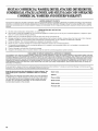
Keep this book and your salesslip together for future reference. You
must provide proofof purchase or installationdate for in-warranty
service.
Write down the following information about your major appliance
to better help you obtain assistance or service if you ever need it.
You will need to know your complete model number and serial
number. You can find this information on the model and serial
number label located on the product.
Dealer name
Address
Phone number
Model number
Serial number
Purchase date
16

SECURITEDULAVE.LINGE
Votre s_curit_ et celle des autres est tr_s importante.
Nous donnons de nombreux messages de s6curit6 importants dans ce manuel et sur votre appareil m6nager. Assurez-vous de
toujours lire tousles messages de s6curit6 et de vous y conformer.
Voici le symbole d'alerte de s6curit6.
Ce symbole d'alerte de s6curit6 vous signale les dangers potentiels de d6ces et de blessures graves a vous
eta d'autres.
Tousles messages de s6curit6 suivront le symbole d'alerte de s6curit6 et le mot "DANGER" ou
"AVERTISSEMENT". Ces mots signifient :
Risque possible de d_c_s ou de blessure grave si vous ne
suivez pas imm_diatement les instructions.
Risque possible de d6c_s ou de blessure grave si vous
ne suivez pas les instructions.
Tousles messages de s6curit6 vous diront quel est le danger potentiel et vous disent comment r6duire le risque de blessure et
ce qui peut se produire en cas de non-respect des instructions.
IMPORTANTES INSTRUCTIONS DE SECURITE
AVERTISSEMENT : Pour reduire les risques d'incendie, de choc electrique ou de blessures Iors de I'utilisation de la
laveuse, suivre les precautions fondamentales dont les suivantes :
[] Dans certaines conditions, de I'hydrog_ne gazeux
peut se former dans un circuit d'eau chaude qui n'a
pas 6t6 utilise pendant 2 semaines ou plus. LE GAZ
HYDROGENE EST EXPLOSIBLE. Si le circuit d'eau
chaude n'a pas 6t6 utilise pendant une telle p6riode,
avant d'utiliser la laveuse, ouvrir tousles robinets
d'eau chaude et laisser I'eau s'6couler pendant
plusieurs minutes par chaque robinet. Ceci
permettra 1'6vacuation de I'hydrogene gazeux
accumule. Comme ce gaz est inflammable, ne pas
fumer ou utiliser une fiamme nue au cours de cette
p6riode.
[] Avant de mettre le lave-linge au rebut ou hors de service,
enlever la porte ou le couvercle.
[] Ne pas installer ou remiser ce lave-linge a un endroit oQ elle
serait exposee aux intemperies.
[] Ne pas reparer ou remplacer un composant quelconque du
lave-linge, ni entreprendre une operation de service, si ce
n'est specifiquement recommande dans ce manuel ou dans
un manuel d'instructions de reparations destine &I'utilisateur;
ilest alors essentiel que la personne concernee comprenne
ces instructions et soit competente pour les executer.
[] Voir "Specifications electriques" pour les instructions de
liaison &la terre.
CONSERVEZ CES INSTRUCTIONS
17

EXIGENCESD'INSTALLATION
Rassembler les outils et pieces necessaires avant de commencer
I'installation. Les pieces fournies se trouvent dans le tambour du
lave-linge.
Outils n_cessaires au raccordement des tuyaux d'arriv_e
d'eau
• Pince (ouverture jusqu'& • Lampe de poche
39,5 mm [1 9/16"]) (facultative)
Outils n_cessaires & I'installation
• Cles plates de W" et 9/16" •
• Tournevis de securit6 •
Torx ot T-20
• Tourne-ecrou de 1/4"
Niveau
Cale en bois
Regle ou metre ruban
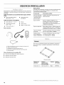
Pibces fournies
A B D
Autres pi_ces
IIse peut que I'installation necessite des pieces supplementaires.
Pour acheter I'un des articles indiqu6s ici, contacter votre
concessionnaire Maytag agre&
Si vous avez Vous devrez acheter
Evier de buanderie Systeme de pompe de puisard (si non
ou tuyau de rejet a deja disponible)
I'egout plus haut
que 2,4 m (96")
Egout surelev6 Evier de vidange standard de 76 L
(20 gal.) de 762 mm (30") de hauteur ou
evier utilitaire et pompe de puisard
(disponibles chez votre fournisseur local
d'articles de plomberie)
Egout au plancher Brise-siphon, piece n° 285834; tuyau de
vidange additionnel, piece n° 8318155; et
ensemble de connexion, piece n° 285835
Tuyau de vidange Trousse de rallonge du tuyau de vidange
trop court de 1,2 m (4 pi), piece n° 285863
Robinets d'eau 2 tuyaux d'admission d'eau plus longs :
hors d'atteinte des 1,8 m (6 pi), piece n° 76314
tuyaux d'admission 3 m (10 pi), piece n° 350008
E
A. Bride de retenue pour tuyau de vidange (en forme de U)
B. Tuyaux d'arriv#e d'eau (2)
C. Rondelles pour tuyau d'arriv#e d'eau (4)
D. Bouchons d'obturation des boulons de transport (4)
E. Courroie perl#e
Pibces fournies pour les modules PD :
• Came de verrouillage de la porte de service
• Detecteur de pieces blanc
• Detecteur de pieces noir
Pi_destal
Vous avez la possibilite d'acheter des piedestaux separ6ment
pour ce lave-linge. Le piedestal augmentera la taille totale du
lave-linge.
Pigdestal facultatif
Hauteur du Hauteur Couleur Num_ro
pi_destal approximative de module
avec lave-linge
73 mm (2 7/8") 1207 mm (47,5") Blanc WHP040
18
t® TORX est une marque d6pos&e de Acument Intellectual Properties, LLC.

Le choix d'un emplacement approprie pour le lave-linge en
ameliore le rendement et reduit au minimum le bruit et le
"deplacement" possible du lave-linge.
Le lave-linge peut _tre installe sous un comptoir personnalise,
dans un sous-sol, une salle de buanderie, un encastrement. Voir
"Systeme de vidange".
IIfaut aussi prendre en compte les exigences d'emplacement
des appareils voisins. C'est a I'utilisateur qu'incombe la
responsabilite de realiser une installation correcte.
II vous faudra
• Un chauffe-eau configure pour fournir de I'eau a 60°C
(140°F) au lave-linge.
• Une prise electrique reliee a la terre situ6e a moins de
1,8 m (6 pi) du cordon d'alimentation electrique fixe a I'arriere
du lave-linge. Voir "Specifications electriques'.
• Des robinets d'eau chaude et d'eau froide situes a moins
de 1,2 m (4 pi) des robinets d'admission d'eau chaude
et d'eau froide et une pression d'eau de 137,9-689,6 kPa
(20-100 Ib/po2).
• Un plancher de niveau ayant une pente maximale de
25 mm (1") sous I'ensemble du lave-linge. L'installation du
lave-linge sur des surfaces de sol molles, telles que tapis
ou surfaces avec sous-couche en mousse n'est pas
recommandee.
• Un plancher robuste et solide capable de soutenir le poids
total du lave-linge (eau et charge) de 180 kg (400 Ib).
Ne pas faire fonctionner le lave-linge a des temperatures
inferieures a 0°C (32°F). Une quantite d'eau peut demeurer dans
le lave-linge et causer des dommages a des temperatures
basses.
D_gagements de s_paration _ respecter
• L'emplacement doit _tre assez grand pour permettre d'ouvrir
completement la porte du lave-linge.
• Prevoir davantage d'espace pour faciliter I'installation et
I'entretien. La porte s'ouvre a plus de 90 ° et n'est pas
reversible.
• Un espace supplementaire peut _tre requis pour les moulures
de porte et de plancher et pour les plinthes.
• Un espace supplementaire de 25 mm (1") de tousles c6tes
du lave-linge est recommande pour reduire letransfert du
bruit.
• II faut aussi prendre en compte I'espace requis entre les
appareils voisins.
• Une fois installees, les prises principales doivent _tre
accessibles pour permettre le debranchement du lave-linge.
Dimensions du lave-linge
_,__...............1282
(501/2,,)
686 mm
(27")
732mm
(2813/16")
La porte n'est pas r#versible.
Un systeme de vidange au plancher doit _tre installe sous la
cloison. Des cloisons pre-fabriqu6es avec prises de courant,
canalisations d'arrivee d'eau et amenagements pour installation
de vidangeage ne doivent _tre installees que la o_ les codes
Iocaux I'autorisent.
19

Le lave-linge peut _tre installe en utilisant le systeme de rejet
I'egout (au plancher ou mural), le systeme de vidange de I'evier
de buanderie ou le systeme de vidange au plancher. Selectionner
la methode d'installation du tuyau de vidange selon les besoins.
Voir "Outillage et pieces".
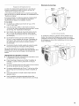
Syst_me de rejet _ I'_gout - mural ou au plancher
(vues A et B)
Le systeme de rejet a I'egout necessite un tuyau rigide d'un
diametre minimum de 50 mm (2"). La capacite minimale
d'acheminement ne doit pas _tre inferieure a 64 L (17 gal.) par
minute.
Le sommet du tuyau de rejet a I'egout doit _tre au moins
762 mm (30") de hauteur et au maximum a2,4 m (96") de la base
du lave-linge.
1
782mm
{30"rain.}
A
Syst_me de vidange avec _vier de buanderie (vue C)
L'evier de buanderie doit avoir une capacite minimale de
76 L (20 gal.). La partie superieure de I'evier de buanderie doit
_tre a au moins 762 mm (30") au-dessus du plancher.
Syst_me de vidange au plancher (vue D)
Le systeme de vidange au plancher necessite un brise-siphon qui
peut _tre achete separement. Voir "Outillage et pieces".
Le brise-siphon doit _tre au moins a 710 mm (28") de la base
du lave-linge. Des tuyaux supplementaires peuvent _tre requis.
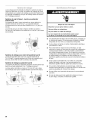
Risque de choc _lectrique
Brancher sur une prise reli_e _ la terre.
Ne pas utiliser un adaptateur.
Ne pas utiliser un c_ble de rallonge.
Le non-respect de ces instructions peut causer
un d_c_s, un incendie ou un choc _lectrique.
Une alimentation electrique de 220-240V, 50 Hz, protegee par
un fusible est requise. On recommande d'utiliser un fusible
temporise de 10 a 16 A ou un disjoncteur temporise.
Ce lave-linge comporte un cordon d'alimentation electrique
pour liaison a la terre.
Pour minimiser les risques de choc electrique, on doit
brancher le cordon sur une prise de courant de configuration
correspondante reliee a la terre et installee conformement
aux codes et reglements Iocaux. Si une prise de courant de
configuration correspondante n'est pas disponible, le client a
la responsabilite et I'obligation de faire installer par un
electricien qualifie une prise de courant correctement reliee
la terre.
Si les codes le permettent et si on utilise un conducteur
distinct de liaison a la terre, il est recommande qu'un
electricien qualifie verifie la qualite de la liaison a la terre.
Si le cordon d'alimentation est endommage, il doit _tre
remplace par le fabricant, son agent de service ou toute autre
personne qualifiee afin d'eviter tout danger.
Ne pas utiliser une tuyauterie de gaz pour le raccordement
la terre.
En cas de doute quant a la qualite de la liaison a la terre
du lave-linge, consulter un electricien qualifie.
C D
20
La page charge ...
La page charge ...
La page charge ...
La page charge ...
La page charge ...
La page charge ...
La page charge ...
La page charge ...
La page charge ...
La page charge ...
La page charge ...
La page charge ...
-
 1
1
-
 2
2
-
 3
3
-
 4
4
-
 5
5
-
 6
6
-
 7
7
-
 8
8
-
 9
9
-
 10
10
-
 11
11
-
 12
12
-
 13
13
-
 14
14
-
 15
15
-
 16
16
-
 17
17
-
 18
18
-
 19
19
-
 20
20
-
 21
21
-
 22
22
-
 23
23
-
 24
24
-
 25
25
-
 26
26
-
 27
27
-
 28
28
-
 29
29
-
 30
30
-
 31
31
-
 32
32


Maytag MAH22PDAGW0 Guide d'installation
- Catégorie
- Machines à laver
- Taper
- Guide d'installation
- Ce manuel convient également à
dans d''autres langues
Documents connexes
-
Maytag MHN30PNBGW Installation Instructions Manual
-
-
-
-
-
Maytag MHN31PRAWW Installation Instructions Manual
-
-
-