
1.26.21 357-00031-01 Rev A © Inovonics, 2021 - www.inovonics.com
Mobile Duress Pendant Family
Installation Instructions
1 Overview
The Inovonics mobile duress pendant is designed to provide indoor room
and floor level location with a button press. Inovonics mobile duress
pendants are only available to factory trained dealers and only compatible
with the EN7295 mobile duress gateway and EN5060 locators.
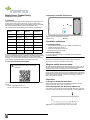
The mobile duress pendant is available in the following configurations:
Inovonics mobile duress pendants are shipped in bulk packaging so that
orders can be fulfilled by removing pendants and batteries from packaging
based on order quantity. Single pendant orders may be repackaged
separately. To re-close the box after batteries are inserted into pendants,
remove battery compartment divider at perforation along hinge.
1.1 Inovonics Contact Information
If you have any problems with this procedure, contact Inovonics technical
support:
• E-mail: [email protected].
• Phone: (800) 782-2709; (303) 939-9336.
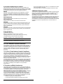
1.2 Pendant Transmitter Components
Figure 1 Pendant Transmitter components
2 Installation and Startup
2.1 Installation Notes
• These products are designed to be installed and maintained by
professional security technicians.
• Products are intended for indoor use.
• Manually test all products weekly.
2.2 Install the Battery
1. Pry the housing apart at either end and pull the two halves apart.
2. Install the battery.
Caution: Ensure that a new Panasonic CR2 or equivalent battery is always
installed in the mobile duress pendant. Never install a used battery.
3. Press the reset button to initialize the transmitter.
3 Register mobile duress pendants
All mobile duress pendants must be registered with the system in order to
be used, monitored and supervised. When supervised, the mobile duress
pendants will send check-in message to the Inovonics gateway.
Note: These instructions cover installation and operation of the mobile
duress pendant. Please refer to the Inovonics Mobile Duress User Manual
for instructions about registering pendants to a specific site’s mobile duress
system. Please contact support or your account manager if you do not
have a copy of the user manual.
4 Operation
4.1 Using The EN2233 Pendant Chain
Always use the chain included with the EN2233. Substituting stronger
cords or chains may result in injury to the wearer.
4.2 Converting a Belt Clip Pendant to a Belt Loop
If you’d like to convert a belt clip pendant transmitter belt clip to a belt loop,
secure the bottom of the belt clip to the housing with a coarse thread screw.
Figure 2 Use a coarse thread screw to secure the belt clip
Part # Type Buttons Conditions
EN2224 Belt clip Four Fifteen
EN2233D Necklace Two One
EN2233S Necklace One One
EN2235D Belt clip Two One
EN2235S Belt clip One One
EN2236D Belt clip Two Three
EN2238D Belt clip Two Two
For product and installation videos visit us at
www.inovonics.com/videos or use the QR
code below.
AReset button BBattery
A
B

1.26.21 357-00031-01 Rev A © Inovonics, 2021 - www.inovonics.com 2
4.3 Operate the Mobile Duress Pendant
Alarm signals are transmitted multiple times and are indicated by the
blinking transmission LED. When the buttons are released, the transmitter
sends an alarm restoral signal. To test a transmitter, activate each condition
by pressing the button(s) and ensure the appropriate response.
EN2224
Activation of the conditions will depend on the application, as will the
response. The application controller must be designed to recognize
simultaneous messages. The EN2224 requires the use of an Inovonics
serial receiver, and cannot currently be used with an Inovonics add-on
receiver.
EN2233D/EN2235D
Press and hold both buttons simultaneously to activate an alarm.
EN2233S/EN2235S
Press the button for at least one second to activate an alarm.
EN2236D
To send the first condition, press and hold the left pendant button for one
second; to send the second condition, press and hold the right pendant
button for one second; to send the third condition, press and hold both
buttons simultaneously.
EN2238D
To send the first condition, press and hold either the left or the right pendant
button for one second; to send the second condition, press and hold both
buttons simultaneously.
5 Specifications
Typical battery life: 3 years.
Battery type (BAT608): Panasonic CR2 or equivalent.
Operating environment: 0 to 60°C (32 to 140°F), noncondensing.
Compatible gateway: EN7295 mobile duress gateway.
Regulatory compliance: FCC, Industry Canada, RoHS
Note: Specifications and data are subject to change without notice.
Note: Inovonics supports recycling and reuse whenever possible. Please
recycle these parts using a certified electronics recycler.
6 FCC RF Radiation Exposure Statement
This equipment complies with FCC radiation exposure limits set forth for an
uncontrolled environment. End users must follow the specific operating
instructions for satisfying RF exposure compliance. This transmitter must
not be co-located or operating in conjunction with any other antenna or
transmitter except in accordance with FCC multi-transmitter product
procedures.
7 FCC Part 15 and Industry Canada Compliance
This device complies with part 15 of the FCC Rules and Industry Canada
license-exempt RSS standard(s). Operation is subject to the following two
conditions: (1) this device may not cause interference, and (2) this device
must accept any interference, including interference that may cause
undesired operation of the device. Changes or modifications not expressly
approved by the party responsible for compliance could void the user's
authority to operate the equipment.
Le présent appareil est conforme aux CNR d'Industrie Canada applicables
aux appareils radio exempts de licence. L'exploitation est autorisée aux
deux conditions suivantes : (1) l'appareil ne doit pas produire de brouillage,
et (2) l'utilisateur de l'appareil doit accepter tout brouillage radioélectrique
subi, même si le brouillage est susceptible d'en compromettre le
fonctionnement.
8 Television and Radio Interference
This equipment has been tested and found to comply with the limits for a
Class B digital device, pursuant to Part 15 of the FCC Rules. These limits
are designed to provide reasonable protection against harmful interference
in a residential installation. This equipment generates, uses and can
radiate radio frequency energy and, if not installed and used in accordance
with the instructions, may cause harmful interference to radio
communications. However, there is no guarantee that interference will not
occur in a particular installation. If this equipment does cause harmful
interference to radio or television reception, which can be determined by
turning the equipment off and on, the user is encouraged to try to correct
the interference by one or more of the following measures:
• Reorient or relocate the receiving antenna.
• Increase the separation between the equipment and receiver.
• Connect the equipment into an outlet on a circuit different from that to
which the receiver is connected.
• Consult the dealer or an experienced radio/TV technician for help.
9 Radiation Exposure Limits
This equipment complies with ISED RSS-102 radiation exposure limits set
forth for an uncontrolled environment. End users must follow the specific
operating instructions for satisfying RF exposure compliance. This
transmitter must not be co-located or operating in conjunction with any
other antenna or transmitter.
Cet équipement est conforme avec ISED RSS-102 des limites d'exposition
aux rayonnements définies pour un environnement non contrôlé. Les
utilisateurs finaux doivent suivre le fonctionnement spécifiqueinstructions
pour satisfaire la conformité à l'exposition RF. Cet émetteur doitne pas être
colocalisé ou fonctionner conjointement avec une autre antenne ou
émetteur.
-
 1
1
-
 2
2


