Johnson Controls TM-11x1 series Installation Instructions Manual
- Taper
- Installation Instructions Manual

TM-11x1 Series Room Temperature Module Installation Instructions 1
Applications
The TM-11x1 Series of Room Temperature Modules
are designed for use with the TC-9102 Direct Digital
Control (DDC) terminal unit controller. The setpoint dial
enables the room occupant to adjust the working
setpoint of the controller. On scaled models, the
marked adjustment range is 55 to 85°F; the controller
determines the actual setpoint. On Warmer/Cooler
models, the adjustment range is marked +/-
from the
midpoint of the dial; the controller determines the
equivalent setpoint temperature.
With the occupancy button, the occupant can switch
the controller’s operating mode between occupied and
standby. In addition, the TM-11x1 Series offers the
option of a temporary occupied mode during
unoccupied mode.
The TM-11x1 Series Room Temperature Module also
features a Light-Emitting Diode (LED) that indicates the
current operating mode.
For TC-9102 Fan Coil Unit controllers, a Room
Temperature Module with a 3-speed fan override
adjustment is available, and models without a
temperature sensor are provided for applications
where the room temperature sensor is mounted inside
the Fan Coil Unit.
Installation
Parts Included
Two #6-32 x 7/8 in. (22 mm) wallbox mounting screws
are included with the TM-11x1 Module.
Special Tools Needed
For tightening and loosening the TM-11x1 Series Room
Temperature Module security screw, order the optional
Allen-head tool (T-4000-119) from the nearest
Johnson Controls® representative.
IMPORTANT: The TM-11x1 Series Room
Temperature Modules are intended to provide an
input to equipment under normal operating
conditions. Where failure or malfunction of the
TM-11x1 Temperature Module could lead to
personal injury or property damage to the controlled
equipment or other property, other precautions must
be designed into the control system. Incorporate and
maintain other devices, such as supervisory or
alarm systems, or safety or limit controls intended to
warn of or protect against failure or malfunction of
the TM-11x1 Temperature Module.
TM-11x1 Series Room Temperature Module
Installation Instructions
Part No. 24-10225-4, Rev. C
Issued March 2016
24- 10225- 4, Rev. C

TM-11x1 Series Room Temperature Module Installation Instructions2
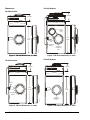
Dimensions
TM-1141 Modules
TM-1151 Modules
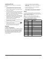
TM-1161 Modules
TM-1191 Modules
Figure 1: TM-1141 Dimensions, in. (mm)Figure 1: TM-1141 Dimensions, in. (mm)
3.15 (80)
1.26 (32)
4.72
(120)
F
I
G
:
T
M
4
1
_
d
i
m
Figure 2: TM-1151 Dimensions, in. (mm)
F
I
G
:
T
M
5
1
_
d
i
m
Mode
LED
Occupancy
Button
3.15 (80)
1.26 (32)
4.72
(120)
Figure 3: TM-1161 Dimensions, in. (mm)
F
I
G
:
T
M
6
1
_
d
i
m
1.38 (35)
4.72
(120)
3.15 (80)
Mode
LED
Occupancy
Button
Fan
Speed
Dial
Setpoint
Adjustment
Dial
Figure 4: TM-1191 Dimensions, in. (mm)
F
I
G
:
T
M
9
1
_
d
i
m
3.15 (80)
1.38 (35)
4.72
(120)
Setpoint
Adjustment
Dial

TM-11x1 Series Room Temperature Module Installation Instructions 3
Installing the TM-11x1
To install the TM-11x1 Series Room Temperature
Module:
1. Use the Allen-head tool to loosen the security
screw located at the top center of the housing.
2. Insert a screwdriver blade or coin into the slot on
the top of the housing.
3. Press down gently, and pry the housing away from
the base. As the two parts separate, remove the
blade or coin and continue to pull the housing away
from the base until the housing is free.
4. Pull the wires through the base. Locate the green
terminal blocks in the upper right of the base and
position the module on the wallbox with the
terminal numbers right-side up.
5. Mount the base to the wallbox using the two #6-32
mounting screws (included).
6. Wire the controller to the module. See the Wiring
section for correct wiring.
7. Attach the housing to the base and tighten the
security screw with the allen-head tool.
Mounting
Location Considerations
Mount the TM-11x1 Series Room Temperature Module
on a wall in the room to be controlled. Locate it where
the occupant can easily read and adjust the setpoint
dial or fan speed override adjustment dial. Consider
these additional guidelines to determine the best
mounting location:
• Avoid areas subject to excessive vibration,
electrical noise, direct sunlight, or the effects of
radiant heat.
• Keep electrical wiring as short as possible to
minimize temperature error.
• Install modules in areas where the temperature is
representative of the general room conditions.
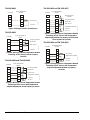
Wiring
To wire a TC-9102 Controller to the TM-11x1 Series
Room Temperature Module, see the appropriate wiring
diagram (Figure 5 to Figure 9).
Note: Use 22 AWG (0.65 mm diameter) wire
minimum. Do not exceed 164 ft (50 m) between the
controller and the temperature module.
Table 1: Nominal Values for Sensors
Temperature Resistance
F Cohm
20 -7 10,595.0
30 -1 7,739.2
40 4 6,010.0
50 10 4,482.3
60 16 3,378.3
70 21 2,689.6
80 27 2,063.9
90 32 1,666.9
100 38 1,300.2
110 43 1,063.9
120 49 842.47
130 54 697.65

TM-11x1 Series Room Temperature Module Installation Instructions4
TM-1141-0000
TM-1151-0000
TM-1161-0000 and TM-1161-0005
TM-1161-0002 and TM-1161-0007
TM-1191-0000 and TM-1191-0005
Figure 5: Wiring to an NTC Room Sensor
F
I
G
:
T
M
4
1
_
W
I
R
21
20
21
20
NTC Sensor
Common
Controller
Room Temperature
Module
Figure 6: Wiring to a Room Temperature Module
Featuring an NTC Sensor with Occupancy
Override
F
I
G
:
T
M
5
1
_
W
I
R
15 15
14 14
21
20
21
20
NTC Sensor
Common
Mode LED
Occupancy Button
Controller
Room Temperature
Module
Figure 7: Wiring to a Room Temperature Module
Featuring an NTC Sensor with Temperature
Setpoint Adjustment, and Occupancy Override
F
I
G
:
T
M
6
1
_
W
I
R
15
14
21
20
NTC Sensor
Common
Mode LED
Occupancy Button
23
22
15
14
21
20
23
22
Controller
Room Temperature
Module
DC +5 V
Temperature Setpoint
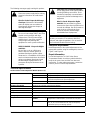
Figure 8: Wiring to a Room Temperature Module
Featuring an NTC Sensor with Temperature
Setpoint Adjustment, Occupancy Override, and
Three-Speed Fan Override
F
I
G
:
T
M
6
1
_
W
I
R
2
15
14
21
20
NTC Sensor
Common
Mode LED
Occupancy Button
23
22
15
14
21
20
23
22
DC +5 V
Temperature Setpoint
Controller
Room Temperature
Module
51 51 Three-Speed Fan
Override
Figure 9: Wiring to a Room Temperature Module
Featuring an NTC Sensor with Temperature
Setpoint Adjustment without Occupancy
Override
F
I
G
:
T
M
9
1
_
W
I
R
20
21 Common
NTC Sensor
23
22
20
21
23
22
DC +5 V
Temperature Setpoint
Controller
Room Temperature
Module

TM-11x1 Series Room Temperature Module Installation Instructions 5
The following messages apply to wiring this product.
Setup and Adjustments
Make temperature or fan speed adjustments to the
appropriate modules using the rotating dial, shown in
Figure 3 and Figure 4.
Repair Information
Do not field repair the TM-11x1 Series Room
Temperature Module. As with any electrical device,
keep the air vents clean and free from dust and
obstruction. To order replacement parts, contact the
nearest Johnson Controls representative.
Technical Specifications
!
CAUTION: Risk of Electric Shock.
Disconnect power supply before making
electrical connections to avoid electric
shock.
Mise En Garde: Risque de décharge
électrique. Débrancher l'alimentation
avant de réaliser tout raccordement
électrique afin d'éviter tout risque de
décharge électrique.
!
CAUTION: Risk of Property Damage.
Do not run low voltage cable in the same
conduit or wiring troughs with high
voltage wires. Running low and high
voltage wires in the same conduit or
wiring troughs may damage the
equipment or cause system malfunction.
MISE EN GARDE : Risque de dégâts
matériels.
Ne pas faire courir un câble basse
tension dans les mêmes gaines ou
goulottes électriques que des câbles
haute tension. L'installation de fils basse
tension et haute tension dans les mêmes
gaines ou goulottes électriques risque
d'endommager l'équipement ou de
provoquer des dysfonctionnements du
système.
!
CAUTION: Risk of Property Damage.
Do not apply power to the system before
checking all wiring connections. Short
circuited or improperly connected wires
may result in permanent damage to the
equipment.
Mise En Garde: Risque de dégâts
matériels. Ne pas mettre le système
sous tension avant d'avoir vérifié tous les
raccords de câblage. Des fils formant un
court-circuit ou connectés de façon
incorrecte risquent d'endommager
irrémédiablement l'équipement.
IMPORTANT: Use copper conductors only. Make
all wiring connections in accordance with local,
national, and regional regulations. Do not exceed
the Command Module electrical ratings.
TM-11x1 Series Room Temperature Module (Part 1 of 2)
Models TM-1141-0000 Temperature Output Only
TM-1151-0000 Temperature Output with Occupancy Override
TM-1161-000x Temperature Output with Setpoint Adjustment and Occupancy
Override and Optional Fan Speed Adjustment
TM-1191-000x Temperature Output with Setpoint Adjustment
Power Requirements Powered from TC-9102 Controller.
Power Consumption N/A: Refer to individual component specification.
Inputs None
Adjustments Temperature Setpoint, Fan Speed (Optional by Model)
Mode Indicator Green LED (5 V, 4 mA)
Occupancy Button Momentary Contact (Switches 5 V at 1 mA)
Output Temperature Sensing
Element
Resistance Temperature Device (RTD) Thermistor Negative
Temperature Coefficient (NTC) 2,252 ohm at 77°F (25°C)
Fan Speed 10k ohm Potentiometer, with Mechanically-Guided Positions
at 0, 25, 50, 75, and 100% for Auto, Off, I (Low Speed),
II (Medium Speed), and III (High Speed)

Published in U.S.A. www.johnsoncontrols.com
TM-11x1 Series Room Temperature Module Installation Instructions6
Metasys® and Johnson Controls® are registered trademarks of Johnson Controls, Inc.
All other marks herein are the marks of their respective owners. © 2016 Johnson Controls, Inc.
Building Efficiency
507 E. Michigan Street, Milwaukee, WI 53202
The performance specifications are nominal and conform to acceptable industry standards. For application at conditions beyond these
specifications, consult the local Johnson Controls office. Johnson Controls, Inc. shall not be liable for damages resulting from misapplication or
misuse of its products.
Setpoint Range TM-1141-0000
TM-1151-0000
No setpoint range
TM-1161-0000
TM-1191-0000
10k ohm potentiometer marked for 55 to 85°F
TM-11x1-0002 10k ohm potentiometer marked for 55 to 85°F
Fan Speed Adjustment: Auto, Off, I, II, and III
TM-11x1-0005 10k ohm potentiometer marked for +/- (5F°)
TM-11x1-0007 10k ohm potentiometer marked for +/- (5F°)
Fan Speed Adjustment: Auto, Off, I, II, and III
Accuracy ±0.9°F (±0.5°C)
Field Connection 18 to 22 AWG (1.00 to 0.65 mm diameter) recommended
Mounting Wallbox Mount
Housing Material ABS + PC, Self-Extinguishing HB UL94
Protection IP30 (EN 60529)
Ambient Operating Conditions Temperature 32 to 122°F (0 to 50°C)
Humidity 10 to 90% RH (Noncondensing)
Ambient Storage Conditions Temperature -40 to 158°F (-40 to 70°C)
Humidity 5 to 95% RH (Noncondensing)
Dimensions
(H x W x D)
TM-1141
TM-1151
4.72 x 3.15 x 1.26 in.
(120 x 80 x 32 mm)
TM-1161
TM-1191
4.72 x 3.15 x 1.38 in.
(120 x 80 x 35 mm)
Shipping Weight 0.44 lb (0.2 kg)
Compliance Europe CE Mark: EMC Directive, EN-61000-6-2
European Single Point of Contact: NA/SA Single Point of Contact: APAC Single Point of Contact:
JOHNSON CONTROLS
WESTENDHOF 3
45143 ESSEN
GERMANY
JOHNSON CONTROLS
507 E MICHIGAN ST
MILWAUKEE WI 53202
USA
JOHNSON CONTROLS
C/O CONTROLS PRODUCT
MANAGEMENT
NO. 22 BLOCK D NEW DISTRICT
WUXI JIANGSU PROVINCE 214142
CHINA
TM-11x1 Series
Room Temperature Module (Part 2 of 2)
-
 1
1
-
 2
2
-
 3
3
-
 4
4
-
 5
5
-
 6
6


Johnson Controls TM-11x1 series Installation Instructions Manual
- Taper
- Installation Instructions Manual
dans d''autres langues
- English: Johnson Controls TM-11x1 series
Documents connexes
-
Johnson Controls TM-2161 Installation Instructions Manual
-
-
-
-
-
-
-
-
-