
www.westermo.com
WeOS
Wolverine
DDW-142-EX
Industrial Ethernet Extender

2
6642-22501

6642-22501
General information
Legal information
The contents of this document are provided “as is”. Except as required by applicable law,
no warranties of any kind, either express or implied, including, but not limited to, the
implied warranties of merchantability and fitness for a particular purpose, are made in
relation to the accuracy and reliability or contents of this document. Westermo reserves
the right to revise this document or withdraw it at any time without prior notice.
Under no circumstances shall Westermo be responsible for any loss of data or income or
any special, incidental, and consequential or indirect damages howsoever caused.
More information about Westermo can be found at the following Internet address:
www.westermo.com
Software tools
Related software tools are available in the folder software tools under technical support
on the Westermo website.
License and copyright for included Free/Libre Open Source Software
This product includes software developed by third parties, including Free/Libre Open
Source Software (FLOSS). The specific license terms and copyright associated with the
software are included in each software package respectively. Please visit the product web
page for more information.
Upon request, the applicable source code will be provided. A nominal fee may be charged
to cover shipping and media. Please direct any source code request to your normal sales
or support channel.
WeOS Management Guide
This product runs WeOS (Westermo Operation System). Instructions for quick start,
configuration, factory reset and use of USB port are found in the WeOS Management
Guide at www.westermo.com.

4
6642-22521
4
Safety
Before installation:
Read this manual completely and gather all information on the unit. Make sure
that you understand it fully. Check that your application does not exceed the safe
operating specifications for this unit.
This unit should only be installed by qualified personnel.
This unit should be built-in to an apparatus cabinet, or similar, where access is
restricted to service personnel only. Refer to Specific Conditions of Use.
The power supply wiring must be sufficiently fused, and if necessary it must be
possible to disconnect manually from the power supply. Ensure compliance to
national installation regulations.
This unit uses convection cooling. To avoid obstructing the airflow around the unit,
follow the spacing recommendations (see Cooling section).
"Note that this unit can be connected to two different power sources."
Before mounting, using or removing this unit:
Prevent access to hazardous voltage by disconnecting the unit from power supply.
Warning! Do not open connected unit. Hazardous voltage may occur within this
unit when connected to power supply.
When this unit is operated at an ambient temperature above +60°C (+140°F),
forced ventilation is required to not exceed Touch Temperature Limits according
to UL/IEC/EN 60950-1. A recommended airflow 32CFM (61m3/h) located 17cm
(7") below the unit is a minimum requirement. To reduce the risk of fire, use only
No. 26 AWG or larger telecommunication line cord.
Care recommendations
Follow the care recommendations below to maintain full operation of unit and to fulfil
the warranty obligations.
This unit must not be operating with removed covers or lids.
Do not attempt to disassemble the unit. There are no user serviceable parts inside.
Do not drop, knock or shake the unit, rough handling above the specification may cause
damage to internal circuit boards.
Do not use harsh chemicals, cleaning solvents or strong detergents to clean the unit.
Do not paint the unit. Paint can clog the unit and prevent proper operation.
Do not expose the unit to any kind of liquids (rain, beverages, etc). The unit is not
waterproof. Keep the unit within the specified humidity levels.
Do not use or store the unit in dusty, dirty areas, connectors as well as other mechanical
part may be damaged.
If the unit is not working properly, contact the place of purchase, nearest Westermo
distributor office or Westermo Tech support.
A readily accessible disconnect device shall be incorporated external to the equipment.
This unit may have hot surfaces when used in high ambient temperature.
Maintenance
No maintenance is required, as long as the unit is used as intended within the specified
conditions.
!
!

5
6642-22521
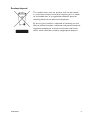
This symbol means that the product shall not be treated
as unsorted municipal waste when disposing of it. It needs
to be handed over to an applicable collection point for
recycling electrical and electronic equipment.
By ensuring this product is disposed of correctly, you will
help to reduce hazardous substances and prevent potential
negative consequences to both environment and human
health, which could be caused by inappropriate disposal.
Product disposal

6
6642-22521
ATEX certification
ATEX certification number
Baseefa 14ATEX 0151X
Standards
EN 60079-0:2012, EN 60079-15:2010
Certification code
Ex nA IIC T4 Gc (–40°C ≤ Ta ≤ +70°C)
ATEX code
II 3G
Specific Conditions of Use
The equipment must be installed in an area of not more than pollution degree 2 in
accordance with IEC/EN 60664-1, and in an enclosure that provides a minimum degree of
protection of at least IP54 and complies with the relevant requirements of EN 60079-0
and EN 60079-15.
All external connections to the equipment must not be inserted or removed unless
either the area in which the equipment is installed is known to be non-hazardous, or the
circuits connected have been de-energized.
The network cables once installed must be properly fixated by the use of cable ties or
similar to reduce the risk of accidently withdrawing the plugs.
Equipment input parameters
Power Connector: +DC1, +DC2 & –COM
Working Voltage Range = 24 V to 48 VDC.
I/O Connector: ‘Status +’ & ‘Status –’ and ‘Digital in +’ and ‘Digital in –’
Maximum I/P Voltage = 60 VDC.

7
6642-22521
ATEX-Zertifizierung
ATEX-Zulassungsnummer
Baseefa 14ATEX 0151X
Standards
EN 60079-0:2012, EN 60079-15:2010,
Zertifizierungscode
Ex nA IIC T4 Gc (–40°C ≤ Ta ≤ +70°C)
ATEX-Code
II 3G
Spezifische Einsatzbedingungen
Die Geräte müssen in einem Bereich welcher einem maximalen Verschmutzungsgrad der
Stufe 2 gemäß IEC/EN 60664-1 entspricht und in einem Gehäuse, das einen Schutzgrad
von mindestens IP54 bietet und die relevanten Anforderungen von N 60079-0 und EN
60079-15 erfüllt, installiert werden.
Alle Anschlüsse des Gerätes dürfen nur dann angeschlossen oder abgeschlossen werden,
wenn der Bereich, in dem das Gerät installiert ist, nachweislich ungefährlich oder das
Gerät völlig spannungsfrei ist.
Die Netzwerkkabel müssen nach der Installation mithilfe von Kabelbindern oder
ähnlichem Material ordnungsgemäß befestigt werden, um ein versehentliches Abziehen
der Stecker zu verhindern.
Eingangsparameter der Geräte
Stromversorgung: +DC1, +DC2 & –COM
Betriebsspannungsbereich = 24 V to 48 VDC.
I/O-Anschluss: ‘Status +’ & ‘Status –’ und ‘Digital in +’ und ‘Digital in –’
Maximale I/P-Spannung = 60 VDC.

8
6642-22521
Certification ATEX
Numéro de certification ATEX
Baseefa 14ATEX 0151X
Normes
EN 60079-0:2012, EN 60079-15:2010
Code de certification
Ex nA IIC T4 Gc (–40°C ≤ Ta ≤ +70°C)
Code ATEX
II 3G
Conditions spéciales d'utilisation
L'équipement doit être installé dans une zone où le degré de pollution ne dépasse pas le
degré 2 conformément à l'IEC/EN 60664-1, et dans un boîtier qui fournit un niveau de
protection au moins égal à IP54 et conforme aux exigences applicables à EN 60079-0 et
EN 60079-15
Toutes les connexions externes à l'équipement ne doivent pas être insérés ou retirés sauf
si la zone dans laquelle l'équipement est installé est reconnue comme non dangereuse, ou
si les circuits raccordés sont hors-tension.
Une fois les câbles réseau installés, ils doivent être correctement fixé grâce à des attaches
de câbles ou autre élément semblable afin de réduire le risque de débranchement
accidentel.
Paramètres d'entrée des équipements
Connecteur d'alimentation : +DC1, +DC2 & –COM
Double entrée d'alimentation 24 V à 48 VCC
Connecteur E/S : « Statut + » et « Statut – » et « Entrée digitale + » et « Entrée digitale – »
Tension maximale I/P = 60 VCC.

9
6642-22521
General
This unit is intended for use in Zone 2 hazardous location only.
Marking
II 3G
Ex nA IIC T4 Gc
SPECIAL CONDITION
ATEX Information
Indicate that this unit complies with relevant European standards that are
harmonised with the 2014/34/EU Directive (ATEX).
II
Equipment group II.
This unit can be installed in all places with an explosive gas atmosphere other
than mines susceptible to firedamp.
3
Equipment category 3.
A category is the classification according to the required level of protection.
This unit ensures the requisite level of protection during normal operation and
is intended for use in areas in which explosive atmosphere caused by gases,
vapours, mists, or dust mixtures are unlikely to occure or, if they do occure, are
likely to do so only infrequently and for a short periode only.
G
Indicates protection concerning explosive atmospheres caused by gases,
vapours or mists (G).
Ex Indicates that this unit is in conformity with relevant European Ex standard(s).
nA
The type of protection used.
This unit is a non-sparking device "nA" which is constructed to minimize the risk
of occurence of arcs or sparks capable of creating an ignition hazard during
conditions of normal operation.
IIC Gas group, a typical gas i hydrogen.
T4
Temperature class T4 (T4 = 135 °C).
This unit is classified in accordance with its maximum surface temperature
(external and internal).
Gc
Equipment protection level Gc (EPL Gc).
Equipment for explosive gas atmospheres, having a "enhanced" level of
protection, which is not a source of ignition in normal operation and which may
have some additional protection to ensure that it remains inactive as an ignition
source in the case of regular expected occurences.
EPL Gc are analogous to the ATEX Categories (Category 3 G = EPL Gc).
SPECIAL
CONDITION
This unit has a special condition for safe use.
The special condition for safe use contains safety related information that is
necesarry for the correct installation and safe use.

10
6642-22521
SPECIAL CONDITION FOR SAFE USE
Ambient temperature:
This unit is designed for use in extreme ambient temperature conditions according to the
following: –40ºC ≤ Ta ≤ +70ºC
Installation in an apparatus cabinet:
This unit requires installation in an Ex certified apparatus cabinet suitable for the area of
use and providing a degree of protection of at least IP54.
Resistance to impact:
This unit requires installation in an apparatus cabinet where adequate resistance to
impact is provided by the apparatus cabinet. See "Installation in an apparatus cabinet"
above for requirements on the external apparatus cabinet.
Secureness of plugs:
When this unit is installed in an explosive atmospheres, all connectors must be
mechanically secured to prevent loosening.
Conductor temperature:
When this unit is installed in locations with high ambient temperature, special precautions
shall be taken upon the choice of external conductor(s) and the temperature rating of
the conductor(s).
Directive 2014/34/EU alongside with other directives:
Directive 2014/30/EU (EMC) applies and to assure a safe performance of this unit under
the scope of Directive 2014/34/EU, refer to the electromagnetic immunity level specified
under “Type tests and environmental conditions” in this manual.
Warning marking:
When this unit is installed in an explosive atmospheres, the warning label submitted
together with this unit shall be attached on the unit and visible to the end user.
Standards and date of compliance
ATEX: EN 60079-0: 2012
EN 60079-15: 2010
IECEx: IEC 60079-0: 2011 EDITION 6
IEC 60079-15: 2010 EDITION 4

11
6642-22521
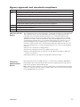
Agency approvals and standards compliance
Type Approval / Compliance
EMC EN 50121-4, Railway signalling and telecommunications apparatus
EN 61000-6-1, Immunity residential environments
EN 61000-6-2, Immunity industrial environments
EN 61000-6-3, Emission residential, commercial and light-industrial environments
EN 61000-6-4, Emission industrial environments
IEC 62236-4, Railway signalling and telecommunications apparatus
Safety UL/IEC/EN 60950-1
Ex EN 60079-0 and EN 60079-15
Marine DNV GL rules for classification – Ships and offshore units
FCC Part 15.105
Notice:
This equipment has been tested and found to comply with the limits for a Class B digital
device, pursuant to Part 15 of the FCC Rules. These limits are designed to provide
reasonable protection against harmful interference in a residential installation. This
equipment generates, uses and can radiate radio frequency energy and, if not installed
and used in accordance with the instructions, may cause harmful interference to radio
communications. However, there is no guarantee that interference will not occur in a
particular installation. If this equipment does cause harmful interference to radio or
television reception, which can be determined by turning the equipment off and on, the
user is encouraged to try to correct the interference by one or more of the following
measures:
… Reorient or relocate the receiving antenna
… Increase the separation between the equipment and receiver
… Connect the equipment into an outlet on a circuit different from that to which the
receiver is connected
… Consult the dealer or an experienced radio/TV technician for help.
Corrosive
environment
Notice:
This product has been successfully tested in a corrosion test according to IEC 60068-
2-60, method 3. This means that the product meets the requirements to be placed in an
environment classified as ISA-S71.04 class G3.
Note! If the product is placed in a corrosive environment, it is important that all unused
connector sockets are protected with a suitable plug in order to avoid corrosion attacks
on the gold plated pins in connectors.

12
6642-22521
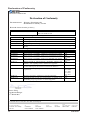
Declaration of Conformity
Westermo Teleindustri AB
Declaration of Conformity
Org.nr/
Postadress/Postal address
Tel.
Telefax
Postgiro
Bankgiro
Corp. identity number
Registered office
S-640 40 Stora Sundby 016-428000 016-428001 52 72 79-4 5671-5550 556361-2604 Eskilstuna
Sweden Int+46 16428000 Int+46 16428001
The manufacturer
Westermo Teleindustri AB
SE-640 40 Stora Sundby, Sweden
Herewith declares that the product(s)
Type of product Models
Industrial Ethernet Extender DDW-142, DDW-142-485, DDW-142-EX
DDW-242, DDW 242-485
is in conformity with the following EU directive(s).
No Short name
2014/30/EU Electromagnetic Compatibility (EMC)
2014/35/EU Low Voltage Directive (LVD)
2014/34/EU
1
Equipment Explosive Atmospheres (ATEX)
2011/65/EU Restriction of the use of certain hazardous substances in electrical and electronic equipment
(RoHS)
References of standards applied for this EU declaration of conformity.
No Title Issue
EN 61000-6-1 Electromagnetic compatibility – Immunity for residential environments 2007
EN 61000-6-2 Electromagnetic compatibility – Immunity for industrial environments 2005
EN 61000-6-3 Electromagnetic compatibility – Emission for residential environments 2007
+A1:2011
EN 61000-6-4 Electromagnetic compatibility – Emission for industrial environments 2007
+A1:2011
EN 50121-4 Railway applications – Electromagnetic compatibility – Emission and
immunity of the signalling and telecommunications apparatus
2015
EN 50581 Technical documentation for the assessment of electrical and electronic
products with respect to the restriction of hazardous substances
2012
EN 60950-1 Information technology equipment -- Safety -- General
requirements
2006
+A11:2009
+A1: 2010
+A12:2011
+A2: 2013
EN 60079-0
1
Explosive atmospheres - Equipment - General requirements 2012
EN 60079-15
1
Electrical apparatus for explosive gas atmospheres - Construction, test
and marking of type of protection "n" electrical apparatus
2010
1
Only applicable for DDW-142 EX. Certificate: Baseefa14ATEX0151X. Issued by: SGS Baseefa Limited, Rockhead Business Park,
Staden Lane, Buxton, Derbyshire, SK17 9RZ, United Kingdom.
Pierre Öberg
Technical Manager
9
th
March 2017

13
6642-22521
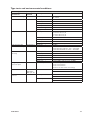
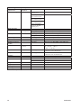
Type tests and environmental conditions
Electromagnetic Compatibility
Environmental
phenomena
Basic
standard
Description Test levels
Electrostatic discharge EN 61000-4-2 Enclosure Contact: ± 6 kV
Air: ± 8 kV
Fast transients EN 61000-4-4 Power port ± 2 kV
Ethernet ports ± 2 kV
SHDSL ports ± 2 kV
RS-232 port ± 2 kV
Status out / Digital in ± 2 kV
Earth port ± 1 kV
Surge EN 61000-4-5 Power port L-L: ±0.5 kV, 2 Ω, 18 μF
L-E: ±0.5 kV, 12 Ω, 9 μF
L-E: ±2 kV, 42 Ω, 0.5 μF
L-L: ±1 kV, 42 Ω, 0.5 μF
Ethernet ports L-E: ±2 kV, 2 Ω
SHDSL ports L-E: ±2 kV, 42 Ω, 0.5 μF
RS-232 port L-E: ±2 kV, 2 Ω
Status out / Digital in L-E: ±2 kV, 42 Ω, 0.5 μF
Pulse magnetic field EN 61000-4-9 Enclosure 300 A/m
Radiated RF immunity EN 61000-4-3 Enclosure 20 V/m 80% AM, 1 kHz sine, 80 – 1000 MHz
12 V/m 80% AM, 1 kHz sine, 1000 – 2700 MHz
10 V/m 80% AM, 1kHz sine, 2700 – 6000 MHz
Conducted RF
immunity
EN 61000-4-6 Power port 10 V, 80% AM, 1 kHz sine; 0.15 – 80 MHz
Ethernet ports 10 V, 80% AM, 1 kHz sine; 0.15 – 80 MHz
SHDSL ports 10 V, 80% AM, 1 kHz sine; 0.15 – 80 MHz
RS-232 port 10 V, 80% AM, 1 kHz sine; 0.15 – 80 MHz
Status out / Digital in 10 V, 80% AM, 1 kHz sine; 0.15 – 80 MHz
Earth port 10 V, 80% AM, 1 kHz sine; 0.15 – 80 MHz
Voltage dips
and interruption
EN 61000-4-29 DC Power port 10 ms, interruption
500 ms, 30% reduction
200 ms, 60% reduction
+20 above & –20% below rated voltage
Radiated RF emission CISPR 16-2-3
ANSI C63.4
(FCC part 15)
Enclosure Class B
Class B
Conducted RF
emission
CISPR 16-2-1 Power port Class B
Class B
Ethernet ports Class B
Class B

14
6642-22521
Electromagnetic Compatibility
Environmental
phenomena
Basic
standard
Description Test levels
Dielectric strength EN 60950-1 Power port to other
isolated ports
2000 Vrms 50 Hz 1 min
Ethernet ports to all
other isolated ports
1500 Vrms 50 Hz 1 min
RS-232 port to all
other isolated ports
SHDSL ports to all
other isolated ports
Status out / Digital
in port to all other
isolated ports
Environmental
Temperature EN 60068-2-1
EN 60068-2-2
Operating –40 to +70ºC (–40 to +158ºF)
Storage & Transport –40 to +85ºC (–40 to +185ºF)
Humidity EN 60068-2-30 Operating 5 to 95% relative humidity
Storage & Transport 5 to 95% relative humidity
Corrosive gases IEC Operating Method 3, 21 days*
Altitude Operating 2 000 m / 70 kPa
Service life Operating 10 years
Reliability prediction
(MTBF)
Operating 437,000 hours (MIL-HDBK- 217F2, GB, 25°C)
Vibration IEC 60068-2-64
(random)
Operating 5 – 20 Hz: 2 m²/s³
20 – 500 Hz: – 3 dB/oct
3 axis = 3 * 30 min
Shock IEC 60068-2-27 Operating 6 ms 1000 m/s²
6 directions, 3 shocks/direction
Bump IEC 60068-2-27 Operating 11 ms 100 m/s²
6 directions, 100 shocks/direction
Packing
Enclosure material EN 60950-1 Zinc (fire enclosure)
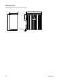
Dimension W x H x D Without connectors 52.5 x 100 x 92 mm
With connectors 52.5 x 100 x 111 mm
Weight 0.8 kg
Degree of protection EN 60529 Enclosure IP40
Cooling Convection
Mounting Enclosure Horizontal on 35 mm DIN-rail
*Method 3, 21 days corresponds to Harsh Industrial Environment G3 which is defined in ANSI/ISA 17.04: 2015

15
6642-22521
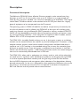
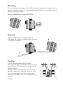
Description
Functional description
The Wolverine DDW-142 allows effec tive Ethernet networks to be created over long
distances up to 15 km (9.3 mi) at data rates up to 15.3 Mbit/s on a single twisted pair
cable. By using two pairs “bonded” this rate can be doubled up to 30.4 Mbit/s. The integral
switch allows 2 Ethernet devices to be attached and an RS-232 port allows for a legacy
piece of equipment to be incorporated into the IP network.
The operating system in DDW-142 (WeOS) can deliver unique security functionality for
this class of product as well as allowing the DDW-142 to form part of a resilient multi-
media ring network using the Westermo FRNT protocol or industry standard STP/RSTP.
WeOS has been developed to provide industrial networking solutions and contains amaz-
ing serial connectivity capability – from being able to simulate an old AT modem, convert
Modbus RTU to TCP or encapsulate serial data into an IP packet.
The DDW-142 is incredibly flexible and easy to use. A basic point to point or multidrop
network can be created without the need for any kind of configuration. If however a more
complex solution requires some kind of network configuration the Web based setup is
simple to use. A CLI interface is also provided making the unit easy for networking pro-
fessionals to quickly master. Once the system is configured an easy solution is also avail-
able for the maintenance engineer – USB backup and restore means that stored configura-
tions can be automatically downloaded from a USB stick.
The DDW-142 is often used in applications on railways, roads or with utilities where fail-
ure could result in significant costs. All Westermo products are designed with high MTBF
in mind to improve operational reliability and also give long service life. Even features
like the SHDSL diagnostics and management allow indication of line degradation allowing
planned main tenance. As the unit is designed for these applications Westermo also ensure
that testing is carried out to ensure the unit can operate at extremes of temperature,
EMC and vibration and still provide robust communications.

16
6642-22521
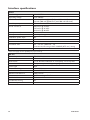
Interface specifications
Power
Rated voltage 24 to 48 VDC
Operating voltage 19 to 60 VDC
Rated current 245 mA (405 mA) @ 24 VDC (with 500 mA USB load)
124 mA (200 mA) @ 48 VDC (with 500 mA USB load)
Rated frequency DC
Inrush current, I²t 10.6 mA²s @ 24 VDC
24.7 mA²s @ 36 VDC
42.4 mA²s @ 48 VDC
Startup current*) 2 x Rated current
Polarity Reverse polarity protected
Redundant power input Yes
Isolation to All other
Connection Detachable screw terminal
Connector size 0.2 – 2.5 mm² (AWG 24 – 13)
Connect the unit using at least 18 AWG (0.75 mm²) wiring
Shielded cable Not required
* External supply current capability for proper start-up.
RS-232
Electrical specification EIA RS-232
Data rate 300 bit/s – 115.2 kbit/s
Data format 7 or 8 data bits, Odd, even or none parity, 1 or 2 stop bits
Protocol Transparent, optimised by packing algorithm
Circuit type SELV
Transmission range 15 m / 49 ft
Isolation to Power, SHDSL, Ethernet
Galvanic connection to USB, Console
Connection RJ-45 according to EIA-561
Shielded cable Recommended
Conductive housing Ye s
Number of ports 1

17
6642-22521
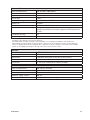
Ethernet TX
Electrical specification IEEE std 802.3. 2005 Edition
Data rate 10 Mbit/s, 100 Mbit/s, manual or auto
Duplex Full or half, manual or auto
Circuit type TNV-1
Transmission range Up to 150 m, with CAT5e cable or better
Isolation to All other
Connection RJ-45, auto MDI/MDIX
Shielded cable Not required, except when installed in Railway applications as
signalling and telecommunications apparatus and located close
to rails.*
Conductive housing Ye s
Number of ports 2
* To minimise the risk of interference, a shielded cable is recommended when the cable is located inside 3 m
boundary to the rails and connected to this port.
The cable shield should be properly connected (360°) to an earthing point within 1 m from this port.
This earthing point should have a low impedance connection to the conductive enclosure of the apparatus
cabinet, or similar, where the unit is built-in. This conductive enclosure should be connected to the earthing
system of an installation and may be directly connected to the protective earth.
Console
Electrical specification LVTTL/LVCMOS-level
Data rate 115.2 kbit/s
Data format 8 data bits, none parity, 1 stop bit, no flow control
Circuit type SELV
Connection 2.5 mm jack, use Westermo cable 1211-2027
USB
Electrical specification USB 2.0 host interface
Data rate Up to 12 Mbit/s (full-speed mode)
Circuit type SELV
Maximum supply current 500 mA
Connection USB receptacle connector type A

18
6642-22521
I/O / Relay output
Maximum voltage/current 60 VDC / 80 mA
Connect resistance Max 30 Ω
Isolation to All other
Connection Detachable screw terminal
Connector size 0.2 – 2.5 mm² (AWG 24 – 13)
I/O / Digital in
Maximum voltage / load current 60 VDC / 2 mA
Voltage levels Logic one >12 V, Logic zero <1V
Isolation to All other
Connection Detachable screw terminal
Connector size 0.2 – 2.5 mm² (AWG 24 – 13)
SHDSL
Electrical specification ITU-T G.991.2 Annex B
Data rate 32 kbit/s to 30.4 Mbit/s with bonding
Protocol EFM according to IEEE 802.3-2005
Transmission range According to ITU-T G.991.2 depending on line quality
Isolation to All other
Connection Detachable screw terminal
Connector size 0.2 – 2.5 mm² (AWG 24 – 13)
Shielded cable Not required
Number of ports 2

19
6642-22521
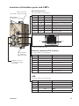
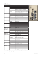
Location of interface ports and LED’s
LED Indicators
(for details see page 15)
Power connection
(for details see page 9 and 13)
I/O connection
(for details see
page 11 and 14)
SHDSL connection
(for details see page
11 and 14)
RS-232 Connection
(for more details see also page 9)
Position Signal Direction* Description
No. 1 DSR Out Data Set Ready
No. 2 DCD Out Data Carrier Detect
No. 3 DTR In Data Terminal Ready
No. 4 SG – Signal Ground, not chassis ground
No. 5 RD
Out
Receive Data
No. 6 TD
In Transmit Data
No. 7 CTS Out Clear To Send
No. 8 RTS In Request To Send
Female
Pin 1Pin 8
* Direction relative this unit.
Ethernet connection TX (2 ports)
(for more details see also page 10)
Position Direction* Description
No.1 In/Out Transmitted/Received data
No. 2 In/Out Transmitted/Received data
No. 3 In/Out Transmitted/Received data
No. 4 Not Connected
No. 5 Not Connected
No. 6 In/Out Transmitted/Received data
No. 7 Not Connected
No. 8 Not Connected
* Direction relative this unit.
USB
(for more details see also page 10)
Position Direction* Description
No.1 Out VBUS
No. 2 In/Out D–
No. 3 In/Out D+
No. 4 Out GND
Shield In/Out Connected to protective earth
* Direction relative this unit.

20
6642-22521
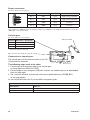
Power connection
(for more details see also page 9)
1
2
3
4
4-position Product marking Direction Description
No. 1 +DC1 Input Supply voltage input DC1
No. 2 +DC2 Input Supply voltage input DC2
No. 3 -COM Input Common
No. 4 -COM Input Common
This unit supports redundant power connection. The positive inputs are +DC1 and +DC2, the negative input for
both supplies are –COM. Connect the primary voltage (e.g. +24 VDC) to the +DC1 pin and return to one of the
–COM pins on the power input.
Connection to console port
The console port can be used to connect to the CLI
(Command Line Interface).
The following steps needs to be taken
1. Connect the serial diagnostic cable to the console port
(use only Westermo cable 1211-2027).
2. Connect cable to your computer (USB port, if drivers are needed they can be downloaded
from our Web page).
3. Use a terminal emulator and connect with correct speed and format (115200, 8N1)
to the assigned port.
For more information about the CLI, see the WeOS management guide.
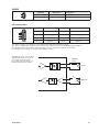
I/O connection (for details see page 11 and 14)
Cable 1211-2027
Bottom view
Accessories
Description Art no
Westermo console cable 1211-2027
RJ45 to DB9 cable 1211-2210
Console port
(for more details see also page 10)
Position Direction* / description
No.1 In / out / GND
No. 2 Out / Tx
No. 3 In / Rx
* Direction relative to this unit.
La page est en cours de chargement...
La page est en cours de chargement...
La page est en cours de chargement...
La page est en cours de chargement...
La page est en cours de chargement...
La page est en cours de chargement...
La page est en cours de chargement...
La page est en cours de chargement...
-
 1
1
-
 2
2
-
 3
3
-
 4
4
-
 5
5
-
 6
6
-
 7
7
-
 8
8
-
 9
9
-
 10
10
-
 11
11
-
 12
12
-
 13
13
-
 14
14
-
 15
15
-
 16
16
-
 17
17
-
 18
18
-
 19
19
-
 20
20
-
 21
21
-
 22
22
-
 23
23
-
 24
24
-
 25
25
-
 26
26
-
 27
27
-
 28
28


dans d''autres langues
- English: Westermo DDW-142-EX User guide
Documents connexes
Autres documents
-
WEG Electric motors for explosive atmospheres Manuel utilisateur
-
SBC Timer KOP...-EX Mounting Instructions & Users Guide
-
Wolf TS-30+ Manuel utilisateur
-
SICK IOLG2EI-03208R01 Quickstart
-
Agrowtek RX1i Manuel utilisateur
-
-
-
Belle Group Premier XT Mode d'emploi
-
Seifert 301530 Le manuel du propriétaire