
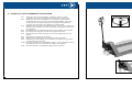
CUSTOMER SERVICE CALL CENTERS/CENTRES DAPPEL POUR LE SERVICE À LA CLIENTÈLE
B.C./Alberta/Saskatchewan Manitoba/Northwest Ontario Ontario/Quebec Atlantic Canada
Tel: (604) 444-5300 Tel: (204) 632-6970 Tel: (905) 502-8665 Tel: (902) 468-8324
Fax: (604) 444-9227 Fax: (204) 694-9534 Fax: (905) 502-7707 Fax: (902) 468-3461
Toll Free: Toll Free: Toll Free: Toll Free:
Tel: 1-800-472-7685 Tel: 1-800-665-7524 Tel: 1-800-387-3879 Tel: 1-800-472-7686
Fax: 1-800-663-7742 Fax: 1-800-267-3310
En français
Sans frais: Tél: 1-800-363-2885
WAREHOUSE LOCATIONS/EMPLACEMENT DES ENTREPÔTS:
Vancouver Edmonton Winnipeg Toronto Montréal Halifax
3260 Production Way 5239 86th Street 951 Powell Avenue 416 Watline Avenue 4620, rue Garand #110-11 Morris Drive
Burnaby, B.C. Edmonton, Alberta Winnipeg, Manitoba Mississauga, Ontario St-Laurent (Québec) Dartmouth, NovaScotia
V5A 4W4 T6E 6T1 R3H 0H4 L4Z 1X2 H4R 2A2 B3B 1M2
www.jetequipment.com
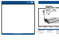
Hand
PALLET TRUCK
PROD. NO. 190918
MOD. NO. PT-5500
Operating INSTRUCTIONS
PARTS LIST

Thank you for purchasing a JET pallet truck. Your pallet truck is made of high quality steel and
was designed to give you a durable, reliable and easy to use product. With proper maintenance,
your JET pallet truck will give you years of trouble free operation.
WARRANTY POLICY
Your JET pallet truck is backed by a nationwide network of distributors and authorized repair
stations. It is guaranteed to be free from defects in materials and workmanship. JET pallet trucks that
fail during the first year of operation due to such defects will be repaired or replaced at our discretion.
Normal wear and tear on moving parts and seals is excluded from this guarantee.This guaratee does
not apply to any product showing signs of misuse, overloading, alteration, or improper maintenance.
WARRANTY PROCEDURE
After receiving authorization from one of our offices, any product for which there is a warranty
claim must be returned prepaid to an authorized warranty depot along with proof of purchase.
1. GENERAL SPECIFICATIONS - MODEL PT-5500 (190918)
Capacity 5500 lbs. / 2500 kg. Fork Length 48" / 1220 mm
Width 27" / 685 mm Min/Max Ht. 2.95 / 7.25", 75 / 185 mm
Weight 209 lbs. / 95 kg
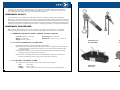
2. TO ATTACH HANDLE TO PUMP UNIT
2.1 Remove 3 bolts (L111A) from handle shaft (L319A).
2.2 Set handle into bracket (L319A), allowing the chain (L114A) and the adjusting bolt
(L116A) assembly to pass through the hole in the centre of the bracket (L319A)
and shaft (L331A).
2.3 Insert the 3 bolts (L111A) through the handle flange into the handle mounting
bracket (L319A), then tighten them securely.
2.4 Raise the lever (L345) and insert the adjusting bolt (L116A) into the front slot,
keeping the adjusting nut (L117A) on the under side of the lever.
3. TO ADJUST CONTROL LEVER
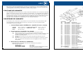
Your pallet truck features a 3 position control lever. Refer to figure 1.
LIFT lever down
DRIVE lever centred
LOWER lever up (The lever returns to the drive position when released)
15
2
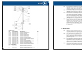
JBC Series
Sèrie JBC
SGP Series
Sèrie SGP
Alsafe Series
Sèrie Alsafe
Mini Mite Series
Sèrie Mini Mite

14
3
3.1 If the forks elevate while pumping in the DRIVE position, turn the adjusting nut
(L117A) on the adjusting bolt (L116A) clockwise until pumping action does not
raise the forks.
3.2 If the forks descend while pumping in the DRIVE position, turn the adjusting nut
(L117A) counter-clockwise until the forks do not lower.
3.3 If the forks do not descend when the control lever is in the LOWER position,
turn the adjusting nut (L117A) clockwise until raising the control lever lowers
the forks. Then check operation in the DRIVE position according to items
3.1 and 3.2.
3.4 If the forks do not elevate while pumping in the LIFT position, turn the adjusting
nut (L117A) counter-clockwise until the forks elevate while pumping in the LIFT
position. Then check operation in the DRIVE and LOWER positions according
to items 3.1, 3.2, and 3.3.
4. MAINTENANCE
4.1 Check oil level every six months. We recommend good quality hydraulic jack
oil. Total volume is approximately 0.3 litres.
4.2 Air may enter the hydraulic oil during transportation or if stored with pump not
in an upright position. To remove air, set control lever to LOWER and pump
several times.
4.3 Daily checks of the pallet truck can limit wear and provide early warning of
problems. Special attention should be paid to the wheels and axles, as string,
rags, etc. can interfere with proper operation of the wheels. See section 5
Guide to Safe Operation for more details.
4.4 All bearings and shafts are provided with long-life grease at the factory.
Frequency of lubrication depends on use, but should be performed monthly
when in regular use.
5. GUIDE TO SAFE OPERATION
5.1 Operator should read manual and all safety warnings before using pallet truck.
5.2 Always move pallet truck with control lever in DRIVE position. This depressurizes
pump and helps to preserve seals and valve components.
5.3 Do not operate pallet truck before checking condition. Give special attention to
wheels and rollers, handle, forks, and foot pedal.
5.4 Do not operate loaded pallet truck on ramps or inclines.
5.5 Do not load beyond rated capacity.
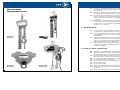
5.6 Ensure load is centred on forks. Refer to figure 2.
5.7 Secure load on forks.
5.8 Do not carry people.
5.9 Keep clear of moving load. Do not place hands or feet beneath forks.
5.10 Do not tip loaded pallet truck. This may cause injury if the rear of the pallet truck
pops up.
5.11 Never leave loaded pallet truck unattended.
L90 Series
Sèrie L90
SBT Series
Sèrie SBT
FA/FA1 Series
Sèrie FA/FA1
Series
Also Available
Disponsibles Aussi
Sèrie

4
13
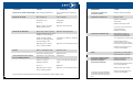
PROBLEM CAUSE SOLUTION
Forks do not raise to full height Not enough hydraulic oil Fill to capacity with hydraulic
jack oil
Forks do not raise Not enough oil Fill to capacity
Impurities in oil Change oil
Air in oil Bleed air
Nut (L117A) is too high Adjust nut per item 3.4
keeping valve open
Forks do not descend Piston rod (L317) or pump Replace damaged parts
body deformed due to over-
loading or slant loading
Forks stored in raised Lubricate rod. Store in lowered
position, exposing piston position
and resulting in rust
Adjusting nut or screw Adjust nut or screw per item 3.3
not in correct position
Leaks Worn or damaged seals Replace seals
Cracked or broken parts Replace parts
Forks descend when control Impurities in oil preventing Change oil
lever in DRIVE position valve from closing
Cracks in parts of Inspect and replace damaged
hydraulic system parts
Air in oil Bleed air
Adjusting nut or screw Adjust nut or screw per item 3.2
not in correct position
Only trained and authorized personnel should attempt to repair pallet trucks.
PROBLEMÈ CAUSE SOLUTION
La fourche ne sélève pas Manque dhuile hydraulique Remplissez dhuile
à sa pleine hauteur hydraulique à pleine capacité
La fourche ne sélève pas Manque dhuile Remplissez à pleine capacité
Présence dimpuretés Changez lhuile
dans lhuile
Présence dair dans lhuile Purgez lair
Lécrou (L117A) est trop haut Réglez lécrou ou la vis
ce qui empêche la selon les consignes du
fermeture du robinet paragraphe 3.4
La fourche ne sabaisse pas Tige de piston (L317) ou Remplacez les pièces
corps de pompe déformés abîmées
en raison dune surcharge
dun chargement en porte-à-faux
Fourche entreposée en Lubrifiez la tige et
position élevée, ce qui cause entrepose lappareil en
la corrosion du piston apparent position abaissée
Position incorrecte de lécrou Réglez lécrou ou la vis
ou de la vis de réglage selon les consignes
du paragraphe 3.3
Fuites Joints usés ou endommagés Remplacez les joints
Pièces fissurées ou brisées Remplacez les pièces
La fourche sabaisse lorsque Présence dimpuretés dans Changez lhuile
le levier de commande se lhuile empêchant la
se trouve en position fermeture du robinet
dentraînement (DRIVE)
Fissures dans certaines pièces Vérifiez et remplacez
du circuit hydraulique les pièces endommagées
Présence dair dans lhuile Purgez lair
Position incorrecte de lécrou Réglez lécrou ou la vis
ou de la vis de réglage selon les consignes du
paragraphe 3.2
La réparation des transpalettes
ne doit être effectuée que par le
personnel formé et autorisé à le
faire.

12
5
5. GUIDE DE FONCTIONNEMENT SÉCURITAIRE
5.1 Avant de se servir du transpalette, lopérateur doit lire le guide
dutilisation et toutes les consignes de sécurité qui sy rapportent.
5.2 Déplacez toujours le transpalette en vous assurant que le levier de
commande se trouve en position dentraînement (DRIVE). Cette façon
de faire permet de réduire la pression de la pompe et de préserver
lintégrité des composants de robinetterie et détanchéité.
5.3 Vérifiez toujours létat du transpalette avant de vous en servir. Prêtez une
attention toute spéciale aux roues, aux galets, à la poignée, à la fourche
et à la pédale.
5.4 Ne déplacez pas le transpalette chargé sur des rampes ou des pentes.
5.5 Ne chargez pas lappareil au-delà de sa capacité nominale.
5.6 Assurez-vous de centrer la charge sur la fourche. Reportez-vous à la
figure 2.
5.7 Arrimez bien la charge sur la fourche.
5.8 Nutilisez pas lappareil aux fins de transport des personnes.
5.9 Éloignez-vous des charges en mouvement et ne placez pas vos mains
ou vos pieds sous la fourche.
5.10 Ne faites pas basculer le transpalette chargé, ce qui risquerait de causer
des blessures lors du soulèvement de larrière de lappareil.
5.11 Ne laissez jamais le transpalette chargé sans surveillance.

6
11
3.1 Si la fourche se soulève lors du pompage en position dentraînement
(DRIVE), tournez lécrou de réglage (L117A) situé sur le boulon de
réglage (L116A) dans le sens des aiguilles dune montre jusquà ce que
leffet de pompage ne provoque plus le soulèvement de la fourche.
3.2 Si la fourche sabaisse lors du pompage en position dentraînement
(DRIVE), tournez lécrou (L117A) de réglage dans le sens contraire des
aiguilles dune montre jusquà ce que la fourche ne sabaisse plus.
3.3 Si la fourche ne sabaisse pas lorsque le levier de commande se trouve
en position dabaissement (LOWER), tournez lécrou (L117A)de réglage
dans le sens des aiguilles dune montre jusquà ce que le relevage du
levier de commande provoque labaissement de la fourche. Vérifiez
ensuite le fonctionnement de lappareil en position dentraînement
(DRIVE) selon les consignes des paragraphes 3.1 et 3.2.
3.4 Si la fourche ne remonte pas lors du pompage en position de levage
(LIFT), tournez lécrou (L117A) de réglage dans le sens contraire des
aiguilles dune montre jusquà ce que le pompage en position de levage
(LIFT) provoque lélévation de la fourche. Vérifiez ensuite le
fonctionnement de lappareil en position dentraînement (DRIVE) et en
position dabaissement (LOWER) selon les consignes des paragraphes
3.1, 3.2 et 3.3.
4. ENTRETIEN
4.1 Vérifiez le niveau dhuile tous les six mois. Nous vous recommandons à
cet égard dutiliser une huile pour vérin hydraulique de bonne qualité
dont le volume total correspond approximativement à 0. 3 litres.
4.2 Lors du transport de lappareil ou de son entreposage alors que la
pompe ne se trouve pas en position verticale, une certaine quantité dair
peut sinfiltrer dans lhuile hydraulique. Pour len extraire, réglez le levier
de commande à la position dabaissement (LOWER) et pompez à
plusieurs reprises.
4.3 Des vérifications quotidiennes du transpalette peuvent en réduire lusure
et permettre de prévenir les problèmes. Prêtez une attention toute
spéciale aux roues et aux essieux, car la ficelle et les chiffons peuvent en
gêner le fonctionnement approprié. Pour plus de renseignements,
reportez-vous au Guide de fonctionnement sécuritaire de la section 5.
4.4 Tous les roulements et les arbres sont garnis de graisse longue durée en
usine. Bien que la fréquence de lubrification dépende de lutilisation de
lappareil, son usage régulier nécessite un graissage mensuel.
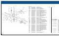
HANDLE TYPE A
REF PART NUMBER DESCRIPTION REQ
L101A PNL-JPT55-L101A JET 5500 P/T SPRING 1
L102A PNL-JPT55-L102A JET 5500 P/T BLADE SPRING 1
L103A PNL-JPT55-L103A JET 5500 P/T ROLLER 1
L104A PNL-JPT55-L104A JET 5500 P/T ELASTIC PIN 1
L105A PNL-JPT55-L105A JET 5500 P/T ELASTIC PIN 1
L106A PNL-JPT55-L106A JET 5500 P/T ELASTIC PIN 1
L107A PNL-JPT55-L107A JET 5500 P/T ELASTIC PIN 1
L108A PNL-JPT55-L108A JET 5500 P/T CONTROL HANDLE 1
L109A PNL-JPT55-L109A JET 5500 P/T P/ BOARD:USE PNL-JPT55-D1 1
L110A PNL-JPT55-L110A JET 5500 P/T HANDLE:USE PNL-JPT55-E1 1
L111A PNL-JPT55-L111A JET 5500 P/T BOLT 3
L112A PNL-JPT55-L112A JET 5500 P/T ELASTIC WASHER 3
L113A PNL-JPT55-L113A JET 5500 P/T PULL ROD:USE PNL-JPT55-D1 1
L114A PNL-JPT55-L114A JET 5500 P/T CHAIN PNL-JPT55-D1 1
L115A PNL-JPT55-L115A JET 5500 P/T PIN:USE PNL-JPT55-D1 1
L116A PNL-JPT55-L116A JET 5500 P/T ADJ/BOLT:USE PNL-JPT55-D1 1
L117A PNL-JPT55-L117A JET 5500 P/T ADJ/NUT:USE PNL-JPT55-D1 1
LIST OF ASSEMBLIES
D1 PNL-JPT55-D1 JET 5500 P/T CHAIN ASSY TYPE A 1
INCLDS L109A,13A,14A,15A,16A,17A
E1 PNL-JPT55-E1 JET 5500 P/T HANDLE ASSY TYPE A 1
INCLDS L101A,2A,3A,4A,5A,6A,7A,8A,9A,10A

10
7
FORK FRAME
REF PART NUMBER DESCRIPTION REQ
L201 PNL-JPT55-L201 JET 5500 P/T CHASSIS N/A 1
L202 PNL-JPT55-L202 JET 5500 P/T LOCK BOLT 1
L203 PNL-JPT55-L203 JET 5500 P/T BUSHING 4
L204 PNL-JPT55-L204 JET 5500 P/T SHOULDER BOLT 2
L205 PNL-JPT55-L205 JET 5500 P/T BUSHING 2
L206 PNL-JPT55-L206 JET 5500 P/T TORSION TUBE 1
L207 PNL-JPT55-L207 JET 5500 P/T THRUST PLATE 1
L208 PNL-JPT55-L208 JET 5500 P/T ELASTIC PIN 4
L209 PNL-JPT55-L209 JET 5500 P/T EYE BOLT 2
L210 PNL-JPT55-L210 JET 5500 P/T NUT 2
L211 PNL-JPT55-L211 JET 5500 P/T PUSH ROD 2
L212 PNL-JPT55-L212 JET 5500 P/T EYE BOLT AXLE 2
L213 PNL-JPT55-L213 JET 5500 P/T ELASTIC PIN 2
L214 PNL-JPT55-L214 JET 5500 P/T TORSION TUBE AXLE 2
L215 PNL-JPT55-L215 JET 5500 P/T ROLLER 2
L216 PNL-JPT55-L216 JET 5500 P/T BUSHING 4
L217 PNL-JPT55-L217 JET 5500 P/T AXLE 2
L218 PNL-JPT55-L218 JET 5500 P/T ELASTIC PIN 4
L219 PNL-JPT55-L219 JET 5500 P/T BUSHING 4
L220 PNL-JPT55-L220 JET 5500 P/T ROLLER FRAME 4
L221 PNL-JPT55-L221 JET 5500 P/T BOLT 2
L222 PNL-JPT55-L222 JET 5500 P/T PIN 2
L223 PNL-JPT55-L223 JET 5500 P/T WASHER 4
L224 PNL-JPT55-L224 JET 5500 P/T ROLLER AXLE 2
L225 PNL-JPT55-L225 JET 5500 P/T BRG:USE PJT-JPT55-F1 4
L226 PNL-JPT55-L226 JET 5500 P/T L/ROLER:USE PJT-JPT55-F1 2
L227 PNL-JPT55-L227 JET 5500 P/T ELASTIC WASHER 2
L228 PNL-JPT55-L228 JET 5500 P/T NUT 2
L229 PNL-JPT55-L229 JET 5500 P/T NUT 2
L230 PNL-JPT55-L230 JET 5500 P/T ENTRY ROLLER 2
L231 PNL-JPT55-L231 JET 5500 P/T BOLT 2
LIST OF ASSEMBLIES
F1 PNL-JPT55-F1 JET 5500 P/T L/ROLLER ASSY SINGLE TYPE 1
INCLDS L225,L226
Merci davoir acheté le transpalette JET. Ce produit, qui est fabriqué en acier de qualité supérieure,
a été conçu pour sa durabilité, sa fiabilité et sa facilité dusage. Si vous lentretenez adéquatement,
votre transpalette vous procurera des années de service sans problème.
POLITIQUE DE GARANTIE
Votre transpalette JET est soutenu par un réseau national de distributeurs et de centres de réparation
agréés. Il est garanti contre tout vice de matériaux et de fabrication. Les transpalettes qui tombent en
panne au cours de la première année de fonctionnement en raison de tels défauts seront réparés ou
remplacés selon notre gré. Lusure normale des pièces mobiles et des joints détanchéité est exclue
de la garantie et cette dernière ne sapplique pas aux produits défectueux par suite dun usage
impropre, dune surcharge, dune modification ou dun entretien inadéquat.
PROCÉDURE DE GARANTIE
Sur réception dune autorisation en provenance dun de nos bureaux, tout produit faisant lobjet
dune déclaration de dommage doit être retourné, port payé, à un centre de garantie agréé,
accompagné dune preuve dachat.
1. CARACTÉRISTIQUES GÉNÉRALES - MODÈLE PT-5500 (190918)
Capacité 5500lb / 2500kg Longueur de la fourche 48po / 1220mm
Largeur 27po / 685mm Hauteur min. / max. 2,95 / 7,25po
Poids 209lb / 95kg (75 / 185mm)
2. FIXATION DE LA POIGNÉE À LA POMPE
2.1 Enlevez les trois boulons (L111A) de laxe de la poignée (L319A).
2.2 Calez la poignée dans le support (L319A) en laissant lensemble chaîne (L114A)
et boulon de réglage (L116A) passer par le trou situé au centre du support
(L319A) et de laxe (L331A).
2.3 Insérez les trois boulons (L111A) dans la poignée (L319A) avant de bien
les serrer.
2.4 Soulevez la levier (L345) et insérez le boulon de réglage (L116A) dans la fente
avant, en prenant soin de maintenir lécrou de réglage (L117A) en dessous
de la pédale.
3. RÉGLAGE DU LEVIER DE COMMANDE
Votre transpalette est équipé dun levier de commande trois positions.
Reportez-vous à la figure 1.
LEVAGE (LIFT) levier abaissé
ENTRAÎNEMENT (DRIVE) levier centré
ABAISSEMENT (LOWER) levier soulevé. Une fois relâché, le levier revient à
la position dentraînement (DRIVE).

8
9
PUMP UNIT
REF PART NUMBER DESCRIPTION REQ
L301N PNL-JPT55-L301N JET 5500 P/T SCREW 1
L302N PNL-JPT55-L302N JET 5500 P/T HUB CAP 1
L303N PNL-JPT55-L303N JET 5500 P/T RETAINING RING 1
L304N PNL-JPT55-L304N JET 5500 P/T WHEEL SHAFT 1
L305N PNL-JPT55-L305N JET 5500 P/T BRG:USE PNL-JPT55-G2 1
L306N PNL-JPT55-L306N JET 5500 P/T W/SHAFT:USE PNL-JPT55-G2 1
L307N PNL-JPT55-L307N JET 5500 P/T RETAINING RING 1
L308 PNL-JPT55-L308 JET 5500 P/T O/R:USE PNL-JPT55-Q 1
L309 PNL-JPT55-L309 JET 5500 P/T REL/VALVE:USE PNL-JPT55-Q 1
L310 PNL-JPT55-L310 JET 5500 P/T SPRING:USE PNL-JPT55-Q 1
L311N PNL-JPT55-L311N JET 5500 P/T PUMP BODY N/A 1
L312 PNL-JPT55-L312 JET 5500 P/T S/WSHR:USE PNL-JPT55-V 1
L313 PNL-JPT55-L313 JET 5500 P/T BOLT 1
L314 PNL-JPT55-L314 JET 5500 P/T Y-SEAL:USE PNL-JPT55-V 1
L315 PNL-JPT55-L315 JET 5500 P/T Y-SEAL:USE PNL-JPT55-V 1
L316 PNL-JPT55-L316 JET 5500 P/T WIPER:USE PNL-JPT55-V 1
L317 PNL-JPT55-L317 JET 5500 P/T LIFT PISTON ROD 1
L318 PNL-JPT55-L318 JET 5500 P/T STEEL BALL 1
L319A PNL-JPT55-L319A JET 5500 P/T TYP A BRK:USE PNL-JPT55-H1 3
L320 PNL-JPT55-L320 JET 5500 P/T PISTON ROD PUMP 2
L321 PNL-JPT55-L321 JET 5500 P/T CAP 1
L322 PNL-JPT55-L322 JET 5500 P/T SPRING 1
L323 PNL-JPT55-L323 JET 5500 P/T WIPER:USE PNL-JPT55-V 1
L324 PNL-JPT55-L324 JET 5500 P/T Y-SEAL:USE PNL-JPT55-V 1
L325A PNL-JPT55-L325A JET 5500 P/T TYP A R/A:USE PNL-JPT55-H1 2
L326A PNL-JPT55-L326A JET 5500 P/T TYP A P/R:USE PNL-JPT55-H1 1
L327A PNL-JPT55-L327A JET 5500 P/T TYP A BSH:USE PNL-JPT55-H1 2
L328A PNL-JPT55-L328A JET 5500 P/T TYP A E/P:USE PNL-JPT55-H1 4
L329A PNL-JPT55-L329A JET 5500 P/T TYPE A ELASTIC PIN 1
L330 PNL-JPT55-L330 JET 5500 P/T BUSHING 1
L331A PNL-JPT55-L331A JET 5500 P/T TYPE A AXLE WITH HOLE 1
L332 PNL-JPT55-L332 JET 5500 P/T BOLT PLUG:USE PNL-JPT55-T 1
L333 PNL-JPT55-L333 JET 5500 P/T SPRING:USE PNL-JPT55-T 1
L334 PNL-JPT55-L334 JET 5500 P/T SEAL WSHR:USE PNL-JPT55-T 1
L335 PNL-JPT55-L335 JET 5500 P/T VALVE PIN:USE PNL-JPT55-T 1
L336 PNL-JPT55-L336 JET 5500 P/T VALVE :USE PNL-JPT55-T 1
L337 PNL-JPT55-L337 JET 5500 P/T O-RING:USE PNL-JPT55-T 1
L338 PNL-JPT55-L338 JET 5500 P/T STL/BALL:USE PNL-JPT55-T 1
L339 PNL-JPT55-L339 JET 5500 P/T S/V/PIN:USE PNL-JPT55-S 1
L340 PNL-JPT55-L340 JET 5500 P/T SPRING:USE PNL-JPT55-S 1
L341 PNL-JPT55-L341 JET 5500 P/T ADJ/BOLT:USE PNL-JPT55-S 1
L342 PNL-JPT55-L342 JET 5500 P/T O-RING:USE PNL-JPT55-S 1
L343 PNL-JPT55-L343 JET 5500 P/T PLUG BOLT:USE PNL-JPT55-S 1
L344 PNL-JPT55-L344 JET 5500 P/T ELASTIC PIN 1
L345 PNL-JPT55-L345 JET 5500 P/T LEVER 1
L348N PNL-JPT55-L348N JET 5500 P/T PIN 1
L349 PNL-JPT55-L349 JET 5500 P/T THRUST BEARING 1
L350 PNL-JPT55-L350 JET 5500 P/T SNAP RING 1
LIST OF ASSEMBLIES
REF PART NUMBER DESCRIPTION REQ
D1 PNL-JPT55-D1 JET 5500 P/T CHAIN ASSY TYPE A 1
INCLDS L109A,13A,14A,15A,16A,17A
E1 PNL-JPT55-E1 JET 5500 P/T HANDLE ASSY TYPE A 1
INCLDS L101A,2A,3A,4A,5A,6A,7A,8A,9A,10A
11A,12A,13A,14A,15A,16A,17A
F1 PNL-JPT55-F1 JET 5500 P/T L/ROLLER ASSY SINGLE TYPE 1
INCLDS L225,L226
G2 PNL-JPT55-G2 JET 5500 P/T STEERING WHEEL ASSY 1
INCLDS L305N,L306N
H1 PNL-JPT55-H1 JET 5500 P/T (TYPE A) BRACKET ASSY 1
INCLDS L319A,25A,26A,27A,28A
P1 PNL-JPT55-P1 JET 5500 P/T (TYPE A) PUMP ASSY 1
INCLDS L308,09,10,11N,12,13,14,15,16,17,18,
19A,20,21,22,23,24,25A,26A,27A,28A,29A,30
31A.32,33,34,35,36,37,38,39,40,41,42,42,43,44
45,49,50,L207
Q PNL-JPT55-Q JET 5500 P/T LOWERING VALVE ASSY 1
INCLDS L308,L309,L310
S PNL-JPT55-S JET 5500 P/T SAFETY VALVE ASSY 1
INCLDS L339,L340,L341,L342,L343
T PNL-JPT55-T JET 5500 P/T HYDRAULIC VALVE ASSY 1
INCLDS L332,33,34,35,36,37,38
V PNL-JPT55-V JET 5500 P/T SEAL KIT PUMP UNIT 1
INCLDS L308,12,14,15,16,23,24,34,37,42
-
 1
1
-
 2
2
-
 3
3
-
 4
4
-
 5
5
-
 6
6
-
 7
7
-
 8
8


Autres documents
-
ITC 024852 Manuel utilisateur
-
 Cal Spas Spas Portables Le manuel du propriétaire
-
Elkay FD70010T1Z Guide d'installation
-
Legrand LMRC-101 Guide de démarrage rapide
-
wattstopper LMSW-105-CCT-LA Guide d'installation
-
Legrand LMFC-011 Dimming Fixture Controller Guide d'installation
-
-
Lightolier LyteCaster LED Accent Install Instructions
-
Mettler Toledo BTA231 Pallet Truck Scale Mode d'emploi
-
Cascade 55K Manuel utilisateur
