
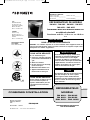
RECORD THIS INFORMATION FOR FUTURE REFERENCE
BEFORE INSTALLING THE UNIT:
Model No. Serial No.
Product No.
Date Purchased Place of Purchase
REFRIGERATOR MODEL
RM 8501 - RM 8505 - RM 8551 - RM 8555
RML 8551 - RML 8555
FOR YOUR SAFETY
If you smell gas:
1. Shut off gas supply at
main valve.
2. Open windows.
3. Don't touch electrical
switches.
4. Extinguish any open
flame.
5. Immediately call your
gas supplier.
WARNING
Improper installation, adjustment,
alteration, service or maintenance
can cause injury or property dama-
ge. Refer to this manual. For assi-
stance or additional information
consult a qualified installer, service
agency or the gas supplier.
AVIS
Cet appareil doit être réparé
seulement par un réparateur
autorisé. Modification de l'appareil
pourrait être extrèmement
dangeruse, et pourrait causer mal
ou mort.
FOR YOUR SAFETY
Do not store or use gasoline
or other flammable vapors
and liquids in the vicinity of
this or any other appliance.
IMPORTANT INSTRUCTIONS
READ CAREFULLY
FOR CHILD SAFETY
DANGER: Risk of child entrapment.
Before you throw away your old
refrigerator: Take off the doors, leave the shelves in place, so that
children may not easily climb inside.
For Mobile Home or Recreational Vehicle
Installation
Operation by LP Gas, 12V DC or 120V AC
Dometic Corporation
LaGrange, IN 46761
USA
822 6102-24
06/2017
FOR SERVICE CENTER
ASSISTANCE
CALL: 800-544-4881
USA
SERVICE OFFICE
The Dometic Corp.
2320 Indust. Parkway
Elkhart, IN 46516
Phone: 574-294-2511
CANADA
Dometic Corp.
46 Zatonski, Unit 3
Brantford, ON N3T 5L8
Canada
Phone: 519-720-9578
FRANÇAIS PAGE 25
INSTALLATION INSTRUCTIONS
REFRIGERATOR
MODEL
RM 8501 - RM 8505
RM 8551 - RM 8555
RML 8551 - RML 8555
© 2007 Dometic - Subject to change without notice
US_EN_RM8xxx-Installation_N2-1.qxp 27.08.2008 13:07 Seite 1

2
Table of contents
0.0 Unpacking and transport . . . . . . . . . . . . . . . . . . . . . . . . . . . . . . . . . 3
1.0 Installation instructions . . . . . . . . . . . . . . . . . . . . . . . . . . . . . . . . . . 4
1.1 Installation . . . . . . . . . . . . . . . . . . . . . . . . . . . . . . . . . . . . . . . . . . . . . . . . . . . . . . . . . . . . . . . . . 4
1.1.1 Side installation . . . . . . . . . . . . . . . . . . . . . . . . . . . . . . . . . . . . . . . . . . . . . . . . . . . . . . . . . . . . . . . . . . . . . 4
1.1.2 Side installation with floor-roof ventilation . . . . . . . . . . . . . . . . . . . . . . . . . . . . . . . . . . . . . . . . . . . . . . . . 5
1.1.3 Rear installation . . . . . . . . . . . . . . . . . . . . . . . . . . . . . . . . . . . . . . . . . . . . . . . . . . . . . . . . . . . . . . . . . . . . 6
1.2 Draught-proof installation . . . . . . . . . . . . . . . . . . . . . . . . . . . . . . . . . . . . . . . . . . . . . . . . . . . . . 6
1.3 Ventilation and air extraction . . . . . . . . . . . . . . . . . . . . . . . . . . . . . . . . . . . . . . . . . . . . . . . . . . . 8
1.4 Installing the ventilation system . . . . . . . . . . . . . . . . . . . . . . . . . . . . . . . . . . . . . . . . . . . . . . . . . 9
1.5 Exhaust duct system . . . . . . . . . . . . . . . . . . . . . . . . . . . . . . . . . . . . . . . . . . . . . . . . . . . . . . . . . 10
1.6 Installation recess . . . . . . . . . . . . . . . . . . . . . . . . . . . . . . . . . . . . . . . . . . . . . . . . . . . . . . . . . . . . 10
1.7 Changing the decor panel . . . . . . . . . . . . . . . . . . . . . . . . . . . . . . . . . . . . . . . . . . . . . . . . . . . . . 12
1.8 Securing the refrigerator . . . . . . . . . . . . . . . . . . . . . . . . . . . . . . . . . . . . . . . . . . . . . . . . . . . . . . 13
1.9 Gas installation . . . . . . . . . . . . . . . . . . . . . . . . . . . . . . . . . . . . . . . . . . . . . . . . . . . . . . . . . . . . . . 14
1.10 Electrical installation . . . . . . . . . . . . . . . . . . . . . . . . . . . . . . . . . . . . . . . . . . . . . . . . . . . . . . . . . . 15
1.10.1 Mains connection . . . . . . . . . . . . . . . . . . . . . . . . . . . . . . . . . . . . . . . . . . . . . . . . . . . . . . . . . . . . . . . . . . . . 15
1.10.2 Battery connection . . . . . . . . . . . . . . . . . . . . . . . . . . . . . . . . . . . . . . . . . . . . . . . . . . . . . . . . . . . . . . . . . . 15
1.10.3 Terminal strip . . . . . . . . . . . . . . . . . . . . . . . . . . . . . . . . . . . . . . . . . . . . . . . . . . . . . . . . . . . . . . . . . . . . . . 16
1.10.4 D+ and solar connection ( only for AES models) . . . . . . . . . . . . . . . . . . . . . . . . . . . . . . . . . . . . . . . . . . . 16
2.0 Tables and wiring diagrams . . . . . . . . . . . . . . . . . . . . . . . . . . . . . . . 18
2.1 Wiring diagrams . . . . . . . . . . . . . . . . . . . . . . . . . . . . . . . . . . . . . . . . . . . . . . . . . . . . . . . . . . . . . 18
2.1.1 Wiring diagram RM 8xx0 . . . . . . . . . . . . . . . . . . . . . . . . . . . . . . . . . . . . . . . . . . . . . . . . . . . . . . . . . . . . . . 18
2.1.2 Wiring diagram RM 8xx1 . . . . . . . . . . . . . . . . . . . . . . . . . . . . . . . . . . . . . . . . . . . . . . . . . . . . . . . . . . . . . . 19
2.1.3 Wiring diagram RM 8xx5 . . . . . . . . . . . . . . . . . . . . . . . . . . . . . . . . . . . . . . . . . . . . . . . . . . . . . . . . . . . . . 20
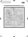
2.1.4 Wiring diagram RM 8xx5 with electrical doorlock (optional) . . . . . . . . . . . . . . . . . . . . . . . . . . . . . . . . . . 21
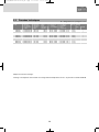
2.2 Technical data . . . . . . . . . . . . . . . . . . . . . . . . . . . . . . . . . . . . . . . . . . . . . . . . . . . . . . . . . . . . . . 22
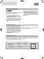
WARNING indicates a potentially hazardous situation
which, if not avoided, could result in death or serious
injury.
CAUTION (used with the safety alert symbol) indicates a
potentially hazardous situation which, if not avoided,
may result in minor or moderate injury.
CAUTION (used without the safety alert symbol) indica−
tes a potentially hazardous situation which, if not avoi−
ded, could result in damage to the appliance.
INFORMATION
WARNING!
CAUTION!
CAUTION!
Explanation of symbols used in this manual
US_EN_RM8xxx-Installation_N2-1.qxp 27.08.2008 13:07 Seite 2

3
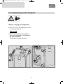
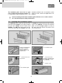
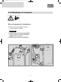
0.0 Unpacking and transport
OK
OK
Lifting / carrying the refrigerator
Always lift or carry the refrigerator by means
of the integrated handles.
Never use for lifting or carrying other
parts of the refrigerator (i.e. cooling unit,
gas pipe, frontpanel) !
The refrigerator will be damaged !
CAUTION!
US_EN_RM8xxx-Installation_N2-1.qxp 27.08.2008 13:07 Seite 3

4
1.0 Installation instructions
On installation of the appliance, the technical
and administrative regulations of the country in
which the vehicle will first be used must be
adhered to. Otherwise the refrigerator must be
installed as described in these instructions.
This appliance is designed for storage of food
and storage of frozen food and making ice. The
refrigerators outlined herein have been design
certified by A.G.A. under ANSI Z21.19
Refrigerator Standard for installation in a mobile
home or recreational vehicle and are approved
by the Canadian Gas Association. The certifica-
tions are, however, contingent on the installation
being made in accordance with the following
instructions as applicable.
In the U.S.A., the installation must conform with:
National Fuel Gas Code ANSI Z223.1 −
(latest edition)
Manufactured Home Construction and
Safety Standard, Title 24 CFR, Part 3280
Recreational Vehicles ANSI A119.2 −
(latest edition)
The unit must be electrically grounded in accor-
dance with the National Electric Code ANSI /
NFPA 70 - (latest edition) when installed if an
external alternating current electrical source is
utilized.
Any applicable local code.
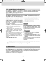
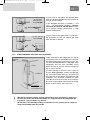
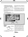
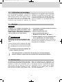
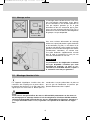
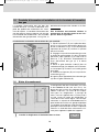
1.1 General instructions
If the appliance is installed on the same side of
the vehicle as the entrance door, it is desirable
that the door does not cover the refrigerator's
vents. (Fig. E1, Clearance door/ventilation grille
at least 1
"). Otherwise ventilation could be
impaired which causes a loss in cooling perfor−
mance. Awnings are often placed at the door
side of a caravan. This complicates evacuation
of combustion gases and heat through the ven−
tilation grilles (loss in cooling performance)!
1.1.1 Side installation
Deviations from these installation instructions without prior notification of Dometic
result in Dometic's warranty obligations becoming void!
In Canada., the installation must conform with:
Current CGA B 149 Gas Installation Codes
Current CSA Standard Z 240.4 GAS−
EQUIPPED RECREATIONAL VEHICLES
AND MOBILE−HOUSING
Any applicable local code
The unit and the exhaust duct system must
be in principle installed so that it is accessi−
ble for maintenance work, can be easily
installed and dismantled and removed from
the vehicle without great effort.
The appliance may only be installed by
authorised personnel.
The appliance shall be installed in such a
way that it is shielded from excessive heat
radiation.
Excessive heat impairs performance and raises
the energy consumption of the
refrigerator.
CAUTION!
WARNING!
US_EN_RM8xxx-Installation_N2-1.qxp 27.08.2008 13:07 Seite 4

5
With this installation method, regular maintenance of the gas burner is only possi-
ble once the device has been dismantled. It is imperative that the refrigerator be
installed in a way to allow easy removal.
We therefore recommend providing an adequate access opening (service flap) for
ready serviceability from the outside.
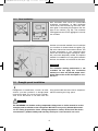
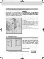
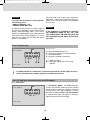
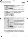
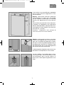
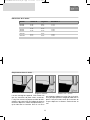
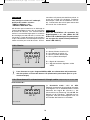
1.1.2 Side installation with floor−roof ventilation
Fig. E1
Fig. E2
Fig. E3
Air vent grille not
blocked! OK!
(Fig. E1) The air vent grilles are blocked. There
must be a distance between the door and the air
vents of at least 25 mm!
If the door/grille distance is between 1
" and
1.77" , we recommend installing a Dometic
ventilation kit (item no. 958 046 000) to achie−
ve an optimal cooling performance in high
ambient temperatures.
(Fig. E2) The air vent grilles offer an unobstruc−
ted dissipation of heat and exhaust gas even
when the door is opened.
Proper ventilation of the refrigerator can also be
achieved by lower air intake aperture in the floor
and upper roof exhaust vent (see Fig. E3). A flue
has to be provided between the top edge of the
refrigerator and the roof ventilation which
directs the hot air and the exhausts straight to
the air vent in the roof.
The floor opening must have a cross section of
at least 30.78 sq inches. Protect the opening,
e.g. with a baffle plate and a net, to prevent dirt
from entering the gas burner. Compared to side
ventilation, this ventilation method can allow
more dirt to enter the rear area of the refrigera-
tor, which makes regular maintenance of the gas
burner, at least once a year, necessary.
floor opening:
at least 50 mm wide,
at least 520 mm long
hot air
condenser
Recommendation:
Roof vent
R500
Air vent grille
blocked by the
door! NOT OK!
US_EN_RM8xxx-Installation_N2-1.qxp 27.08.2008 13:07 Seite 5

6
Rear installation often causes an unfavourable
installation arrangement, as ideal ventilation
cannot always be assured (e.g. the lower venti-
lation grille is covered by the bumper or the rear
lights of the vehicle!) (
Fig. E4
). The maximum
cooling performance of the aggregate is actually
not available.
Another unfavourable method of rear installation
is to install the air intake and exhaust grilles (
Fig.
E6
) at the side wall of the recreation vehicle. The
air-heat recirculation is very restricted which
means that heat exchangers (condenser, absor-
ber) cannot be adequately cooled. The optional
method of an additional air vent grille installed in
the floor also exhibits an insufficient air flow duct.
1.1.3 Rear installation
Fig. E4
Fig. E5
Air vent grille not
blocked! OK!
Fig. E6
The maximum cooling performance is not
available! Do not apply this installation
method, as it does not provide proper venti−
lation! Please refer to the description in sec−
tion E1.3.
CAUTION!
1.2 Draught−proof installation
Refrigerators in motorhomes, caravans or other
vehicles must be installed in a draught-proof
manner (EN 1949). This means that the combu-
stion air for the burner is not taken from the
living space and that exhaust fumes are preven-
ted from entering the living space.
BY NO MEANS use durable sealing compounds, fitting foam or similar material to realise
draught-proof installation of the refrigerator! Do NOT use any easily inflammable materi-
als for sealing (in particular silicon sealing compound or similar). Risk of fire! The device
manufacturer's product liability and warranty shall lapse if such materials are used.
WARNING!
US_EN_RM8xxx-Installation_N2-1.qxp 27.08.2008 13:07 Seite 6

7
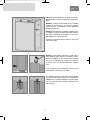
Fig. E8
Fig. E9
Fig. E10
Fig. E11
Fig. E7
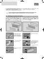
Adequate sealing between the back of the refri-
gerator and the vehicle interior has to be provi-
ded.
Dometic strongly recommend using a flexible
sealing for this purpose, in order to facilitate
future removal or installation of the appliance
during maintenance.
Dometic Refrigerators of RM8xxx Series featu-
re a groove running all around outside and bot-
tom side to facilitate the insertion of such flexi-
ble lipped seals (see Figure E7).
Exception: Stepped cabinets have no groove at
the bottom side
Dometic recommend mounting a strip with a
heat deflector plate into the installation recess
above the appliance. This allows the ascending
hot air to escape directly outside. This deflecti-
on plate must also be provided with a lipped
seal.
That ensures that the refrigerator can easily be
removed for maintenance or repair.
The flexible sealing is pressed into the groove
running around the housing. Press the side pro-
vided with the sealing knob firmly into the groo-
ve. Take care that the sealings uniformly abut
the housing.
Dometic-Sealing-Kit for RM 8xxx:
Item no. :
US_EN_RM8xxx-Installation_N2-1.qxp 27.08.2008 13:07 Seite 7

8
The cavity in-between the outer vehicle wall and
refrigerator is completely isolated from the vehi-
cle interior. Intrusion of exhaust fumes into the
living space is prevented. Fumes will escape
through the upper ventilation grille to the outsi-
de. The draught-proof installation does not
require a special exhaust gas duct to be used.
This installation method allows the use of the
same air vent grille L200 at the top and at the
bottom without flue duct.
If a flue duct is nevertheless desirable, incorpo-
rate the L100 ventilation system with flue duct
into the upper air vent opening. (
For installation,
please refer to "E1.7"
)
Deviations require the consent of the manufacturer!
Fig. E12
Fig. E13
1.3 Ventilation and air extraction of the refrigerator
A correct installation of the refrigerator is essen−
tial for its correct operation, as due to physical
reasons heat builds up at the back of the appli−
ance which must be allowed to escape into the
open air.
In the event of high ambient temperatures, full performance of the cooling unit can
only be achieved by means of adequate ventilation and extraction.
Ventilation is provided for the unit by means of
two apertures in the caravan wall. Fresh air
enters at the bottom, extracts the heat and exits
through the upper vent grille (chimney effect).
The upper ventilation grille should be positio-
ned as high as possible above the condenser
(A). Install the lower ventilation grille at floor
level of the vehicle, allowing unburnt gas (hea-
vier than air) to escape directly into the open air.
Should this arrangement prove impossible, a
ventilation aperture must be introduced by the
manufacturer of the vehicle into the recess floor
in order to avoid the accumulation of unburnt
gas on the floor.
L100
(L200)
L200
ventilation aperture
L100
(L200)
L200
US_EN_RM8xxx-Installation_N2-1.qxp 27.08.2008 13:07 Seite 8

9
Fig. E14
Fig. E15
The ventilation grilles must have an open
cross-section of at least 30.78 sq inches. This
is achieved by using the Dometic L100 / L 200
absorber ventilation and air extraction system
which has been tested and approved for this
purpose.
Fig. E20
Fig. E16
Fig. E17
Fig. E18
Fig. E19
Fig. E21
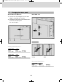
Seal the mounting frame
making it waterproof
(does not apply for
mounting frames with
integral seal)
.
1.
Insert frame and screw
into position.
2.
Insert ventilation grille.
3.
Lock ventilation grille.
4.
Clip the insert for flue
gas duct in position
(only
for L100 upper ventilati-
on system kit).
5.
Insert winter cover.
6.
The L100 upper vent system kit consists of the
mounting frame (R1640), the air grille including
flue gas duct (A1620) and the winter cover
(WA120). The L200 lower vent system kit con-
sists of the mounting frame (R1650), the air gril-
le (A1630, but without flue gas duct) and the
winter cover (WA130). To install the ventilation
grilles, cut two rectangles (69.09
" x 24.18") in
the outer wall of the vehicle (for position of the
cuts, see point 6.3).
Correct mounting of the lower ventilation grille facilitates access to the connecti-
ons and functional parts during maintenance.
1.4 Installing the ventilation system
US_EN_RM8xxx-Installation_N2-1.qxp 27.08.2008 13:07 Seite 9

10
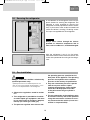
The refrigerator must be installed draught-proof
in a recess (also refer to Section 6.2). The mea-
surements of the recess are stated in the table
below. Step A is only required for cabinets with a
step. Push the appliance far enough into the
recess until the front edge of the refrigerator
casing is aligned with the front of the recess.
Allow a gap of 2.32
"- 3.1" between the back wall
of the recess and the refrigeration unit. The floor
of the recess must be level, allowing the applian-
ce to be pushed easily into its correct position.
The floor must be substantial enough to bear the
weight of the appliance.
1.6 Installation recess
Ensure that the refrigerator is installed level in the recess.
Fig. E23
Installing the standard fume flue:
Fig. E22
1. Connect T-piece (E) to adaptor (F) or flue
pipe (K) as required and affix with screw (G).
Ensure that heat baffle (H) is lodged in the cor-
rect position.
2. Insert flue pipe with cover plate (C) through
the appropriate aperture in the upper frame (I)
and connect to T-piece (E). If necessary, shorten
flue pipe (C) to the required length.
3. Insert L100 ventilation grille (D) into mounting
frame (I) and fasten, using the locking handle on
the left of the grille.
4. Put cap (B) on flue pipe (C).
5. Insert extractor insert (A) into ventilation grille
(D).
The exhaust gas duct system must be made in
such a manner as to achieve a complete extrac-
tion of combustion products to the outside of
living space. The duct system must slope in an
upward direction in order to avoid a build-up of
condensate. The type of exhaust gas duct
shown in Fig. E22 allows the side installation of
the winter cover.
An installation other than described will
reduce the cooling capacity and jeopardise
the manufacturer's warranty/product liability.
1.5 Exhaust gas duct and installing the fume flue
CAUTION!
A
US_EN_RM8xxx-Installation_N2-1.qxp 27.08.2008 13:07 Seite 10

11
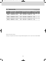
Recess dimensions:
Installation in the recess:
Model Height H Width B Depth T
Note: When installing the appliance ensure that
the door hinges are supported. Figure E24
shows the optimum installation of the refrigera−
tor, whereas Fig. E25 shows the minimum requi−
rement with the maximum clearance between
installation area and end of hinge. If the installa−
tion is carried out as per Fig. E26, the hinge is
not capable of supporting the possible load in
the door. It is therefore essential that the maxi−
mum clearance of 1.57
" not be exceeded.
Ideal fitting
Minimum requirement Distance not greater than 40mm
RM 8501
RM 8505
RM 8551
RM 8555
RML 8551
RML 8555
32.48"
32.48"
32.48"
32.48"
49.17"
49.17"
20.74"
20.74"
20.74"
20.74"
20.82"
20.82"
21.34"
21.34"
23.50"
23.50"
23.58"
23.58"
Fig. E26Fig. E25Fig. E24
US_EN_RM8xxx-Installation_N2-1.qxp 27.08.2008 13:07 Seite 11

12
1.7 Changing the decor panel
Remove the lateral ledge L from the door
(ledge is attached, not screwed).
Shift decor panel P away from the door and
insert the new decor panel.
Re−attach ledge L.
Fig. 37
L
P
Model RM 8xxx, RMS 8xxx
Decor panel dimensions :
Casing wid
th
19.13"
Height Width Thickness
Casing wid
th 20.59"
Height Width Thickness
2
1
Fig. 38a
L
P
Model RML 8xxx
4
1
2
3
Fig. 38b
Fig. 38c
Decor panel dimensions :
Casing width 20.67"
Height Width Thickness
CAUTION!
wrong
right
29.25"+/-0.02 20.00"+/-0.02 max. 0.09"
29.25"+/-0.02 18.58"+/-0.02 max. 0.09"
46.04"+/-0.02 19.98"+/-0.02 max. 0.06"
US_EN_RM8xxx-Installation_N2-1.qxp 27.08.2008 13:07 Seite 12

13
In the sidewalls of the refrigerator, there are four
plastic sleeves for securing the refrigerator. The
sidewalls or strips attached for securing the
refrigerator must be prepared to hold the screws
firmly in place even when under increased load
(while the vehicle is moving). Fastening screws
and caps are supplied with the refrigerator.
Always insert screws through the sleeves
provided as otherwise components laid in
foam, such as cables etc., could be damaged.
After the refrigerator is put in its final place,
secure the screws into the wall of the recess. The
screws must penetrate the casing of the refrige−
rator.
1.8 Securing the refrigerator
Fig. E27
Fig. E28
CAUTION!
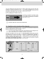
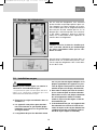
1.9 Gas installation
Observe the regulations stated in section
6.1 !
This refrigerator is provided for installati−
on within liquid gas equipment and must
be run exclusively on liquid gas (propane,
butane) (no natural gas, town gas).
The pressure regulator must concur with
The gas connection shall be carried out by
qualified personnel* only.
WARNING!
* qualified personnel are accredited experts who are
able, by virtue of their training and knowledge, to vouch
for the correct implementation of the leakage test.
the operating pressure specified on the
data plate of the appliance. The operating
pressure corresponds to the standard
pressure of the country of specification.
Only one connection pressure is permis
sible for any one vehicle. A plate
showing the permanent, clearly legible
notice must be displayed in full view
at the point where the gas cylinder is
installed.
The gas connection to the appliance must
be installed securely and at zero potential
using tube connectors and must be secu−
rely connected to the vehicle (a hose con−
nection is not permissible).
US_EN_RM8xxx-Installation_N2-1.qxp 27.08.2008 13:07 Seite 13

14
Inflamable material should not be in
immediate proximity to the burner.
The gas connection to the appliance is
effected by means of a suitable coupling
tube fitting.
Hook−up to the gas supply line is accomplished
at the manual gas shutoff valve,
which is furnished with a 3/8" SAE (UNF 5/8" −
18) male flare connection. Always use a backu
wrench when connecting the gas supply line to
the gas inlet fitting.
The gas connection may only be carried
out by a qualified personnel.
Following proper installation, a testing for leaka−
ge and a flame test must be carried out by
*qualified personnel. A certificate of testing must
be issued.
Check all connections for gas leaks with soap
and water. DO NOT use a naked flame for
detecting leaks. Ignite the burner to ensure cor−
rect operation of gas valve, burner and ignition.
In case the appliance fails to operate correctly
after all checks have been carried out, refer to
the authorised service provider in your area
AATTTTEENNTTIIOONN
20 Nm
max
10 Nm
max
Test point
Connection
of gas supply
Gas burner
SW 14
SW 17
Gas supply
LP GAS
CYLINDER
PRESSURE
REGULATOR
TO
REFRIGERA-
TOR
The refrigerator must be equipped with a gas cock
in the supply line to allow the supply to be discon-
nected. Such a cut-out device must be readily
accessible to the user.
The gas supply system must incorporate a pressu-
re regulator to maintain a supply pressure of not
more than 13.5 inches water column, static (no
load).When testing the gas supply system at test
pressures in excess of 1/2 psig, the refrigerator
and its individual shutoff valve must be discon-
nected from the gas supply piping system.When
testing the gas supply system at pressures less
than or equal to 1/2 psig, the appliance must be
isolated from the gas supply piping by closing its
individual manual shutoff valve.In case detailed
instructions on the installation and connection to
the gas supply are required, contact your dealer or
distributor.
Gas pressure
Refer to data label.
Fig. E29
US_EN_RM8xxx-Installation_N2-1.qxp 27.08.2008 13:07 Seite 14

15
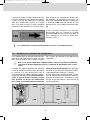
Cable cross sections and cable lengths for caravan/motorhome:
1.10 Electrical installation
The electrical installation must be in
accordance with the national regulations
of the respective countries.
The connection cables must be routed in a
way to prevent contact with hot compo−
nents of the unit/burner or with sharp
edges.
Changes to the internal electrical installa−
tion or the connection of other electrical
components (e.g. external fan) to the
internal wiring of the appliance will render
any claims from warranty and product lia−
bility void!
The electrical installation shall be carried
out by qualified personnel only.
WARNING!
The power should be supplied by a pro−
perly grounded socket outlet or a groun−
ded non−detachable connection. Where a
socket outlet with mains supply is used,
the outlet must be freely accessible.
Should the connection cable be damaged,
have it replaced by Dometic Customer
Services or by qualified personnel to
avoid hazards.
We recommend leading the power supply via a
board-side fuse protection.
1.10.1 Mains connection
1.10.2 Battery connection
The machine's 12V connection cable is connec−
ted (observing correct polarity) to a terminal
strip. The wiring for the heating element (refer to
A, B wiring diagram connections; connection
cable white/red) must be direct and by the shor−
test possible route to the battery or electric
generator.
AWG 11 < 20 ft
AWG 9 > 20 ft
min. AWG 13
Cross section Length
Motorcaravan &
Caravan (inside)
Caravan (outside)
2,5mm²
Fig. E30
US_EN_RM8xxx-Installation_N2-1.qxp 27.08.2008 13:07 Seite 15

16
D+ − connection :
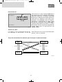
1.10.4 D+ and solar connection (only for AES models)
In >Automatic Mode< the AES electronic
system automatically selects the most efficient
energy supply. In automatic mode the electronic
system uses the D+ signal (dynamo +) of the
alternator to detect 12V DC. 12V DC operation
is selected only while the engine is running in
order to prevent battery discharge.
T
o protect the on-board 12 V circuit provide
the following fuses:
- RM8xxx, RMS8xxx: 15 A
- RML855x, RMSL855x: 20 A
In order to ensure that the 12V power supply is
shut off when stopping the engine (otherwise the
battery would discharge within a few hours),
perform the power supply to the heating element
(connection A/B in wiring diagram) in a way to
have the 12V supply only live while the vehicle
ignition is switched on.
The connection C/D (interior light, electronics,
cable black / violet) must be permanently provi−
ded by a 12V DC power supply to be protected
by a 2A fuse.
If the appliance is installed in a caravan
the respective leads for the 12V+ and
12V- connections A/B and C/D must not
be connected to each other on the cara-
van-side .
CAUTION!
CAUTION!
D+
S+
on the vehicle
on the appliance
Fig. E32
Connections :
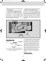
1.10.3 Terminal strip
A = Ground heating element DC
B = Positive connection, heating element DC
C = Ground electronics
D = Positive connection, electronics
D+ = Alternator signal
S+ = AES input signal from solar charge
regulator
AB
D+
S+
CD
-
+
+
-
on the vehicle
on the appliance
Fig. E31
For MES and AES it is compulsory to provide a permanent 12V DC supply at the ter-
minals C/D (permanent voltage supply for functional electronics).
US_EN_RM8xxx-Installation_N2-1.qxp 27.08.2008 13:07 Seite 16

17
S+ − connection :
12V DC energy can be optionally achieved by
mounting solar equipment to the vehicle. The
solar power equipment must be provided with a
solar charging controller with AES output (ade−
quate charging controllers available in selected
stores). The "S+ connection (Solar +) must be
connected to the respective terminal of the solar
charging controller (AES output). The electronic
system uses the S+ signal of the solar charging
controller to detect solar 12V DC.
D+
S+
on the vehicle
on the appliance
Fig. E33
Fig. E34
Cable cross−sectional areas :
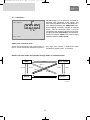
Switch−over time within the individual energy modes in automatic mode:
There are no particularly high current flows via
the D+ and S+ connection; therefore no particu−
larly large cross−section is required for these
connections (approx. 0.04
"˛ is sufficient).
230V
Gas 12V Solar
12V DC
~2-5 s
~2-5 s
~2-5 s
~2-5 s
~2-5 s
~2-5 s
~2-5 s
15 min
~2-5 s
~2-5 s
US_EN_RM8xxx-Installation_N2-1.qxp 27.08.2008 13:07 Seite 17

18
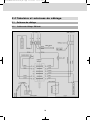
Fig. E35
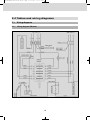
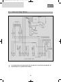
2.0 Tables and wiring diagrams
2.1 Wiring diagrams
2.1.1 Wiring diagram RM 8xx0
US_EN_RM8xxx-Installation_N2-1.qxp 27.08.2008 13:07 Seite 18

19
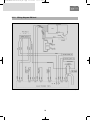
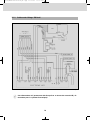
Fig. E36
2.1.2 Wiring diagram RM 8xx1
US_EN_RM8xxx-Installation_N2-1.qxp 27.08.2008 13:07 Seite 19

20
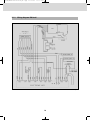
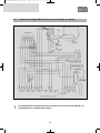
Fig. E37
2.1.3 Wiring diagram RM 8xx5
US_EN_RM8xxx-Installation_N2-1.qxp 27.08.2008 13:07 Seite 20
La page est en cours de chargement...
La page est en cours de chargement...
La page est en cours de chargement...
La page est en cours de chargement...
La page est en cours de chargement...
La page est en cours de chargement...
La page est en cours de chargement...
La page est en cours de chargement...
La page est en cours de chargement...
La page est en cours de chargement...
La page est en cours de chargement...
La page est en cours de chargement...
La page est en cours de chargement...
La page est en cours de chargement...
La page est en cours de chargement...
La page est en cours de chargement...
La page est en cours de chargement...
La page est en cours de chargement...
La page est en cours de chargement...
La page est en cours de chargement...
La page est en cours de chargement...
La page est en cours de chargement...
La page est en cours de chargement...
La page est en cours de chargement...
La page est en cours de chargement...
La page est en cours de chargement...
La page est en cours de chargement...
La page est en cours de chargement...
-
 1
1
-
 2
2
-
 3
3
-
 4
4
-
 5
5
-
 6
6
-
 7
7
-
 8
8
-
 9
9
-
 10
10
-
 11
11
-
 12
12
-
 13
13
-
 14
14
-
 15
15
-
 16
16
-
 17
17
-
 18
18
-
 19
19
-
 20
20
-
 21
21
-
 22
22
-
 23
23
-
 24
24
-
 25
25
-
 26
26
-
 27
27
-
 28
28
-
 29
29
-
 30
30
-
 31
31
-
 32
32
-
 33
33
-
 34
34
-
 35
35
-
 36
36
-
 37
37
-
 38
38
-
 39
39
-
 40
40
-
 41
41
-
 42
42
-
 43
43
-
 44
44
-
 45
45
-
 46
46
-
 47
47
-
 48
48


Dometic RM8501, RM8505, RM8551, RM8555, RML8551, RML8555 Guide d'installation
- Taper
- Guide d'installation
- Ce manuel convient également à
dans d''autres langues
Documents connexes
-
Dometic RM8551 Manuel utilisateur
-
-
-
-
-
Dometic ACC3100D Manuel utilisateur
-
-
-
-