
Allgemeines
Zu Ihrer eigenen Sicherheit lesen Sie auch die Sicherheits-
information, bevor sie das Netzgerätes installieren und in Betrieb
nehmen. Bewahren Sie diese Anleitung und die Sicherheits-
informationen als wichtigen Bestandteil des Produktes auf.
Geben Sie die Anleitung an nachfolgende Besitzer weiter. Weiter-
führende Informationen finden Sie unter
www.recom-power.com.
Vorausgesetzte Kenntnisse und Verantwortungs-
bereiche der Bediener/Anwender
• Dieses Gerät darf ausschließlich von qualifiziertem
Fachpersonal installiert und in Betrieb genommen werden!
• Das Gerät beinhaltet keine zu wartenden Teile. Führen Sie
keine Änderungen oder Reparaturversuche durch!
• Vor jeder Inbetriebnahme des Netzgerätes ist dieses auf
offensichtliche Mängel überprüfen!
• Das Betreiben dieses Netzgerätes ist nur mit den festge-
legten, technischen Spezifikationen erlaubt!.
Fehlbedienung und falsche Installation können Ihre Sicherheit
gefährden.
Stand der Technik
Das Netzgerät ist nach folgenden Standards zertifiziert:
• CE (EMC + RoHS2 + LVD)
• UL
Bestimmungsgemäße Verwendung
Das Netzgerät eignet sich für Netzspannungen im Bereich von
80-264 VAC. Der DC-Ausgang ist gegen Überlastung, Über-
hitzung und Kurzschluss geschützt. Für Schutzklasse I Instal-
lationen ist die Schutzerde bestimmungsgemäß zu montieren.
Für Schutzklasse II Installationen ist der Einbau so vorzuneh-
men dass zu Kühlkörper und primär-seitigen Bauteilen des
Gerätes entsprechende Luftstrecken eingehalten werden.
Installation des Netzgerätes
!WARNUNG
Stromschlag-, Brand-, Verletzungs- und
Lebensgefahr.
Um das Netzgerät zu installieren, gehen Sie wie folgt vor:
Schritt Beschreibung
1 Vor jeglichen Installations- oder Wartungsarbeiten ist
das Netz auf Spannungsfreiheit zu prüfen.
2 Die Montage kann vertikal oder horizontal erfolgen. Eine
Montage kopfüber ist nicht zu empfehlen.
3 Achten Sie auf ausreichende Belüftung, um eine
Überhitzung des Gerätes zu vermeiden! Zu hohe
Betriebstemperaturen verringern die Lebensdauer!
4 Verwenden Sie adäquate Steckverbinder!
5 Eine Montage, welche stark von den Spezifikationen
abweicht, kann den zuverlässigen Betrieb beeinflussen.
Inbetriebnahme des Netzgerätes
Wichtig:
Vor Inbetriebnahme ist zu prüfen:
• Ausgangsspannung und Strom müssen den
Anforderungen entsprechen!
Temperaturverhalten
Siehe unten Leistungsreduzierung. (Fig. 2)
Sicherer Betrieb des Netzgerätes
Betreiben Sie das Netzgerät nur unter jenen Bedingungen und
Umgebungstemperaturen, welche in den „Spezikationen“
angeführt sind.
Folgendes ist zu beachten!
• nicht in defektem Zustand betreiben!
• unter Volllast nur mit ausreichender Kühlung betreiben!
• Installationen nur in einer kontrollierten Umgebung
(Verschmutzungsgrad 2) PD2 durchführen!
Fehler und Fehlerbehebung
Je nach Schutzartmechanismus startet das Gerät nach
Fehlerbehebung automatisch.
Haftung und Gewährleistung
RECOM Power GmbH übernimmt keine Haftung und keine
Gewähr für Schäden, wenn:
• das Netzgerät für andere Zwecke eingesetzt wird, als es
unter „Bestimmungsgemäße Verwendung“ beschrieben wurde
• durch unsachgemäße Bedienung Schaden entsteht
• Änderungen am Netzgerät durchgeführt wurden
• das Netzgerät unsachgemäß installiert wird
• das Netzgerät in defektem Zustand betrieben wird
• das Netzgerät chemischen Einflüssen ausgesetzt wird
• Dokumente nicht aktuell gehalten werden
Demontage und Entsorgung des Netzgerätes
• Versorgungsspannung abschalten!
• Vom Netz trennen!
Das Produkt entspricht dem EG WEEE Elektro- und Elekt-
ronikgerätegesetz. Entsorgen Sie das Verpackungsmaterial
und die Elektrogeräte und deren Komponenten immer über
die hierfür autorisierten Sammelstellen oder Entsorgungs-
betriebe! Nicht über den Hausmüll entsorgen!
Revision: 0/2019
Dokumentnr: IMG126
Ref. Nummer: 240100012304
General information
For your own safety, read the safety information before
installing the power supply and putting it into operation. Keep
these instructions and the safety information as an important part
of the product. Pass them on to any subsequent owner.
For support and additional information, please visit
www.recom-power.com.
Required knowledge and responsibility areas of the user/
operator
• This device may only be installed and put in operation by
qualified personnel.
• There are no user-serviceable parts inside. Do not modify or
repair the unit.
• Check the power supply for visible defects before each use
• The power supply may only be operated within the specified
technical specifications
Incorrect operation and improper installation can endanger your safety.
State of the art
The power supply is tested in accordance with the following
standards:
• CE (EMC + RoHS2 + LVD)
• UL
Intended use
The unit is suitable for supply voltages in the range of 80-264VAC.
All units have input fuses for device protection (not externally
accessable). The unit is output short circuit, over voltage, over load
and over temperature protected. The unit requires a functional
ground connection for EMC. For protection class I installations, the
protective earth must be installed as intended. For protection class
II installations, the installation must be carried out in such a way that
appropriate air gaps are maintained with respect to the heat sink
and the primary-side components of the device.
Installing the Power Supply
!WARNING
Danger of electric shock, fire, injury or loss
of life.
To install the power supply, proceed as follows:
Step Description
1Before any installation or maintenance work, disconnect
and lock-off the mains supply.
2 Mounting orientation can be vertical or horizontal
(see Fig.1). Upside-down mounting orientation is not
suggested.
3 Allow adequate ventilation to prevent overheating,
operation under continuous high temperature may
reduce lifetime.
4 Ensure that all of the strands of each stranded wire
enter the connection to prevent poor contacts or short
circuits. Use an adequate connector set.
5 Any usage which does not comply with the
specifications may decrease the performance or
damage the device.
Putting the Power Supply into operation
Important
Before applying power, check:
• the output current and voltage have to match the
requirements of the application.
Derating .
See derating below. (Fig. 2).
Safe operation of the Power Supply
Operate the power supply only according to the conditions and
the ambient temperatures listed in the Specications.
The power supply should
• not be operated if defective
• not be operated under full load without sufficient cooling
• be installed in a controlled environment compliant with pol-
lution degree 2 (PD2)
Faults and troubleshooting
Depending on degree of protection (mechanism), the device re-
starts automatic after fault condition is removed.
Liability and warranty
RECOM Power GmbH assumes no responsibility and no liability
for damages if:
• the power supply is used for purposes not listed in the
Intended use section
• the power supply is operated outside of specification
• the power supply is modified in any way
• the power supply is improperly installed
• the power supply is operated in a defective condition
• the power supply is exposed to corrosive chemicals or gasses
• the documentation is not kept up to date
Dismantling and disposing of the Power Supply
Disconnect and uninstall the power supply.
The EG WEEE (Waste Electrical and Electronic Equipment)
Directive applies to this product. Always dispose of
packaging material and electrical devices or components
via authorised collection or disposal points, not in
household waste.
RECOM Power GmbH
Münzfeld 35, 4810 Gmunden, AUSTRIA
+43 7612 88325 700 +43 7612 88325 801
* TechsupportAT@recom-power.com 7 www.recom-power.com
EN
Revision: 0/2019
Document no.: IMG126
Reference no.: 240100012304
©RECOM Power GmbH. The information contained in
this instructions and accompanying drawings are the
intellectual property of RECOM Power GmbH.
This manual can change without prior notice.
Installation and Operating Instructions
Powerline AC/DC Power Supply
Model: RACM550-SG/ENC
Other applicable document:
Important Safety Information
Installations- und Betriebsanleitung: AC/DC Netzgerät Modell: RACM550-SG/ENC
©RECOM Power GmbH. Die in dieser Anleitung enthaltenen Informationen und beigelegten Zeichnungen sind geistiges Eigentum der RECOM Power GmbH. Diese Anleitung kann ohne Vorankündigung geändert werden.
Mitgeltendes Dokument:
Wichtige Sicherheitsinformationen
DE

Informations générales
Pour votre propre sécurité, veuillez lire les consignes de sécurité
avant l’installation et la mise en service de l’alimentation
électrique. Conservez ces instructions et les consignes de
sécurité car elles font partie intégrante du produit. Remettez-les
aux propriétaires suivants. Pour tout complément d’information,
veuillez consulter le site www.recom-power.com.
Connaissances requises et domaines de responsabilité
de l’utilisateur/opérateur
• Cet appareil peut uniquement être installé et mis en service par
des personnes qualifiées.
• L’équipement contient des pièces ne pouvant pas être réparées
par l’utilisateur. Il est interdit de modifier ou d’essayer de réparer
l’alimentation électrique.
• Contrôler si l’alimentation électrique présente des défauts vi-
sibles avant chaque utilisation.
• L’utilisation de l’alimentation électrique est uniquement autori-
sée avec les spécifications techniques définies.
Toute utilisation incorrecte et tout montage inapproprié peuvent
mettre en danger votre sécurité.
État de la technique
L’alimentation électrique a été testée conformément aux normes
suivantes :
• CE (EMC + RoHS2 + LVD)
• UL
Utilisation prévue
L’alimentation électrique est prévue pour des tensions d’alimenta-
tion de 80 à 264 VAC.
Toutes les alimentations électriques disposent de fusibles d’en-
trée servant à protéger l’appareil (non accessible de l’extérieur).
L’alimentation électrique est protégée contre les courts-circuits en
sortie, la surtension, la surcharge et la surchauffe. Elle requiert une
prise de terre en état de marche pour la CEM. Pour les installa-
tions appartenant à la classe de protection I, la mise à la terre doit
être installée comme prévu. Pour les installations appartenant à la
classe de protection II, l’installation doit être effectuée de façon à
laisser des intervalles d’air appropriés par rapport au dissipateur de
chaleur et aux composants du côté primaire de l’appareil.
Installation de l’alimentation électrique
!
AVERTISSEMENT
AVERTISSEMENT Risque d’électrocution,
d’incendie, de blessures et danger de mort.
Procéder de la manière suivante pour installer l’alimentation électrique :
Étape Description
1Avant de commencer les travaux de montage ou de
maintenance, déconnecter et mettre l’appareil hors
tension
2Le montage peut être effectué à la verticale ou à
l’horizontale (voir fig.1). Un montage à l’envers n’est
pas recommandé.
3Veiller à ce que la ventilation soit suffisante afin d’éviter
toute surchauffe. Une utilisation à une température
continuellement élevée peut réduire la durée de vie de
l’alimentation électrique
4Veiller à ce que tous les brins de chaque toron soient
bien connectés afin d’éviter les faux contacts et les
courts-circuits. Utiliser un set de connecteurs adéquats.
5Toute utilisation n’étant pas conforme aux spécifica-
tions peut influencer la performance de l’appareil ou
l’endommager.
Mise en service de l’alimentation électrique
Important
À vérifier avant la mise en service :
• le courant et la tension de sortie doivent répondre aux
exigences requises.
Derating
Voir le derating ci-dessous (fig. 2).
Fonctionnement sûr de l’alimentation électrique
L’alimentation électrique doit uniquement être utilisée dans les
conditions et aux températures ambiantes indiquées dans les
spécifications.
L’alimentation électrique
• ne doit pas être utilisée dans un état défectueux
• ne doit pas être utilisée à pleine charge sans refroidissement
suffisant
• doit être installée dans un environnement contrôlé correspon-
dant au degré de pollution 2 (PD2)
Erreurs et résolution des problèmes
Selon le degré (mécanisme) de protection, l’appareil redémarre
automatiquement dès que l’erreur a été supprimée.
Responsabilité et garantie
RECOM Power GmbH décline toute responsabilité et n’accorde
aucune garantie pour les dommages si :
• l’alimentation électrique est utilisée dans d’autres buts que
ceux indiqués dans la partie Utilisation prévue
• l’alimentation électrique est utilisée sans prendre en compte
les spécifications
• l’alimentation électrique est modifiée de quelque façon que
ce soit
• l’alimentation électrique est installée de façon inappropriée
• l’alimentation électrique est utilisée alors qu’elle est défec-
tueuse
• l’alimentation électrique est exposée à des produits chimiques
ou des gaz corrosifs
• a documentation n’est pas tenue à jour
Démontage et mise au rebut de l’alimentation électrique
Débrancher et démonter l’alimentation électrique.
La directive européenne DEEE (déchets d‘équipements
électriques et électroniques s’applique à ce produit.
Toujours éliminer le matériel d’emballage et les appareils
ou composants dans les déchetteries ou les points de
collecte correspondants. Ne pas les jeter avec les ordures
ménagères.
RECOM Power GmbH
Münzfeld 35, 4810 Gmunden, AUSTRIA
+43 7612 88325 700 +43 7612 88325 801
* TechsupportAT@recom-power.com 7 www.recom-power.com
FR
Révision : 0/2019
Document n° : IMG126
Référence n° : 240100012304
©RECOM Power GmbH. Les informations contenues dans
ces instructions et les schémas joints en annexe sont la
propriété intellectuelle de RECOM Power GmbH. Ces inst-
ructions peuvent être modifiées sans notification préalable.
Instructions de montage et d’utilisation
Alimentation électrique CA/CC Powerline
Modèle : RACM550-SG/ENC
Autre document applicable :
Consignes de sécurité importantes
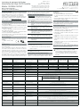
Technical Data
At 230VAC, full load forced air cooling,
25°C, with 5 minute warm-up time unless
otherwise stated
Technischen Daten
Bei 230VAC, Volllast, Zwangsbelüftung, 25°C,
nach 5 Minuten Aufwärmzeit, wenn nicht
anders angegeben
Données techniques
Avec 230 VAC, pleine charge, refroidissement par
air forcé, 25 °C, avec un temps de préchauffage de
5 minutes, sauf indication contraire
RACM550-24SG/ENC RACM550-36SG/ENC RACM550-48SG/ENC RACM550-56SG/ENC
nom. Output Power nom. Ausgangsleistung Puissance de sortie nom. 550W (2.5m/s)
Line Derating Leistungsreduzierung Réduction de puissance refer to graph below / siehe Grafik unten / Voir le diagramme ci-dessous (fig. 2)
Output Voltage (Factory Setting) Ausgangsspannung (Werkseinstellung) Tension de sortie (réglage usine) 24VDC 36VDC 48VDC 56VDC
Output Current max. Ausgangsstrom max. Courant de sortie max. 22.92A 15.28A 11.46A 9.82A
Efficiency Wirkungsgrad Rendement 93% 93% 93% 94%
Input Voltage Range Eingangsspannungsbereich Plage de tensions d’entrée 80-264VAC
AC Input Frequency Range Eingangsfrequenz Plage de fréquences d’entrée CA 47Hz – 63Hz
Input Current Eingangsstrom Courant d’entrée 6.5A max. (115VAC)
Inrush Current (cold start) Einschaltspitzenstrom (Kaltstart) Courant d’appel (démarrage à froid) 40A @115VAC / 60A @ 230VAC
Hold-up Time Pufferzeit Temps de marge 15ms, main output; 130ms, VSB output / 15ms, Hauptausgang; 130ms, VSB Ausgang
15 ms, sortie principale ; 130 ms, sortie VSB
ON/OFF CTRL ON/OFF CTRL MARCHE/ARRÊT CTRL CON3, Pin3
main + FAN output ON / Hauptausgang + Lüfter EIN
Sortie principale + ventilateur MARCHE 2.4VDC - 5VDC or open / oder offen / ou ouvert
main + FAN output OFF / Hauptausgang + Lüfter AUS
Sortie principale + ventilateur ARRÊT
0VDC - 0.8VDC or shorted to GND / oder kurzgeschlossen zu GND /
ou en court-circuit vers GND
VSB Ouptut Power VSB Ausgangsleistung Puissance de sortie VSB CTRL ON= 5W max. / CTRL EIN= 5W max. / CTRL ON (MARCHE) = 5W max.
Fan Output Current Lüfter Ausgangsstrom Courant de sortie ventilateur 250mA typ.; 500mA/1s Peak (not protected) / 250mA typ.; 500mA/1s Spitze (nicht abgesichert)
250 mA typ. ; 500 mA/1 s pic (non protégé)
Short Circuit Protection (SCP) Kurzschlusssicherung Protection contre les courts-circuits (SCP) hiccup mode / automatischer Neustart / Mode « hiccup »
Over Voltage Protection (OVP) Überspannungsschutz Protection contre la surtension (OVP) 110%-120% of nominal output voltage, hiccup mode / 110%-120% der nominalen Ausgangsspannung, automatischer Neustart
110 %-120 % de tension de sortie nominale, mode « hiccup »
Over Current Protection (OCP) Überstromschutz Protection contre la surintensité (OCP) 105%-135% of nominal output current, hiccup mode / 105%-135% des nominalen Ausgangsstromes, automatischer Neustart
105 %-135 % de courant de sortie nominal, mode « hiccup »
Over Temperature Protection (OTP) Übertemperaturschutz Protection contre la surchauffe (OTP) auto recovery, internal temperature sensors / automatischer Neustart nach Abkühlung, interne Sensoren
Récupération automatique, capteurs de température internes
Operating Temperature Betriebstemperatur Température de fonctionnement -40°C to +70°C (with derating, see below / mit Derating, siehe unten) / De -40°C à +70°C (avec derating, voir ci-dessous)
Operating Humidity Betriebsluftfeuchtigkeit Humidité de fonctionnement 20% – 90% RH max.
Storage Conditions Lagerbedingungen Conditions de stockage -55°C to +85°C, 95% RH max.
Operating Altitude Betriebshöhe Altitude de fonctionnement
5000m max.; High altitude operation may impact the performance and lifetime. Please derate output power, when operating >3000m above
sea level. / 5000m max.; Betriebshöhen über 3000m beeinflussen die Lebensdauer und erfordern eine Reduzierung der Ausgangsleistung.
5000 m max. ; une utilisation à une altitude élevée a une influence négative sur la performance et la durée de vie. La puissance de sortie doit
être réduite en cas d’utilisation > 3000 m au-dessus du niveau de la mer.
Dimensions / Weight Abmessungen / Gewicht Dimensions/Poids 127.0 x 76.0 x 38.0mm / 500g typ.
Approvals Zulassungen Homologations IEC/EN62368-1, IEC/EN60335-1, ANIS/AAMI ES60601-1, CSA C22.2 No. 60601-1:14, IEC/EN60601-1, IEC/EN61558-1
IEC/EN61558-2-16
Warranty Garantie Garantie 3 years / 3 Jahre / 3 ans

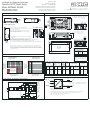
Fig. 4: Mechanical Dimension / Mechanische Dimensionen / Dimensions mécaniques
Fig. 5: Adjustability and Sensing / Regulierbarkeit und Sensing / Réglage et détection
Fig. 1: Mounting / Montage / Montage
Fig. 2: Derating / Leistungsreduzierung / Derating
Fig. 3: Block Diagram / Block Diagramm / Schéma fonctionnel
If module is horizontal or side mounted no derating is required.
If module is mounted vertical or upside down with natural convection cooling, the
power must be derated at least 10%.
With forced air cooling, mounting orientation has no impact on output power.
For convection cooling, ensure sufficient distance to adjacent components!
Device should be fan cooled from DC side.
Wenn das Modul horizontal oder seitlich montiert wird, ist keine Leistungsrück-
nahme erforderlich.
Wenn das Modul, bei natürlicher Konvektionskühlung, senkrecht oder kopfüber
montiert wird, muss die Leistung um mindestens 10% verringert werden.
Bei Anwendung mit Zwangsbelüftung, hat die Montagerichtung keinen Einfluss auf die Ausgangsleistung.
Achten Sie zur Konvektionskühlung auf ausreichenden Abstand zu benachbarten Bauteilen!
Das Gerät muss bei hoher Ausgangsleistung aktiv (Zwangsbelüftung) gekühlt werden. Beströmungsrichtung beachten!
RECOM Power GmbH
Münzfeld 35, 4810 Gmunden, AUSTRIA
+43 7612 88325 700 +43 7612 88325 801
* TechsupportAT@recom-power.com 7 www.recom-power.com
Revision: 0/2019
Document no.: IMG126
Reference no.: 240100012304
©RECOM Power GmbH. The information contained in
this instructions and accompanying drawings are the
intellectual property of RECOM Power GmbH.
This manual can change without prior notice.
Installation and Operating Instructions
Powerline AC/DC Power Supply
Model: RACM550-SG/ENC
Other applicable document:
Important Safety Information
CON2
CON3
CON7CON8 CON6
ADJ
3 4
1 2
LED
1
3
CON4 CON1
150.0
130.0 10.05.0
87.0
45.0
FC 27.5
FC 43.5
FC 58.5FC 14.25
4 x Ø4.5
Ø4.5
FC 134.5 FC 7.75
FC 27.5
Ø4.5
ADJ
CON2
CON7
CON8
CON6
3 4
1 2
21
embossed logo
Ø4.5
CON4
CON1
CON2
CON3
CON7CON8 CON6
ADJ
3 4
1 2
LED
1
3
CON4 CON1
150.0
130.0 10.05.0
87.0
45.0
FC 27.5
FC 43.5
FC 58.5FC 14.25
4 x Ø4.5
Ø4.5
FC 134.5 FC 7.75
FC 27.5
Ø4.5
ADJ
CON2
CON7
CON8
CON6
3 4
1 2
21
embossed logo
Ø4.5
CON4
CON1
CON2
CON3
CON7CON8 CON6
ADJ
3 4
1 2
LED
1
3
CON4 CON1
150.0
130.0 10.05.0
87.0
45.0
FC 27.5
FC 43.5
FC 58.5FC 14.25
4 x Ø4.5
Ø4.5
FC 134.5 FC 7.75
FC 27.5
Ø4.5
ADJ
CON2
CON7
CON8
CON6
3 4
1 2
21
embossed logo
Ø4.5
CON4
CON1
Top View
Draufsicht
vue de dessus
Side View
Seitenansicht
Vue de côté
geprägtes Logo
logo en relief-vue suède
Bottom View
Bodenansicht
Vue du sol
L
ADJ
+Sense
-Sense
+Vout
-Vout
+Fan
-Fan
+5VSB
GND
N
PE
Fuse, Inrush
Current Linitation,
Input Filter
Feedback
and Isolation
Feedback
and Isolation
Rectifier
Rectifier
PWM
Controller
PFC LLC
Controller
Output
Filter
Output
Filter
Rectifier
Flyback
Controller
Rectifier +
Bulk Cap
Isolation
PFC
Boost
Switcher
Transformer
Transformer
PS ON
GND
Thermal Derating (115VAC/230VAC)
Temperaturabhängigkeit
Derating thermique
Line Derating
Eingangsabhängigkeit
Réduction de puissance
Input Voltage [VAC]
115
80 90 100
100
80
90
60
40
70
50
30
20
10
0
Output Load [%]
-40 -20-30 -10 0 10 20 4045
30 50 60 70 80
550
450
350
250
500
400
300
200
150
100
50
0
Output Power [W]
Ambient Temperature [°C]
230VAC, 2.5m/s forced cooling
230VAC, conduction cooling
230VAC, convection cooling
115VAC, 4.5m/s forced cooling
115VAC, conduction cooling
115VAC, convection cooling
FC = fixing centers / Montagelöcher / points de fixation
Tolerance/Toleranz/ Tolérance: xx.x= ±1.0mm
xx.xx= ±0.5mm
-Sense
+Sense
RW1
RW2
-Vout
+Vout
+Vout
-Vout
VAC
in
(L)
VAC
in
(N)
VACIN (L)
PE
VACIN (N)
RW1 ... wire losses + / Spannungsabfall + / Chutes de tension +
RW2 ... wire losses - / Spannungsabfall - / Chutes de tension -
The output voltage can be adjusted by both ADJ (potentiometer) and Sense.
The maximum combined adjustment range is ±2VDC.
La tension de sortie peut être réglée en utilisant ADJ (potentiomètre) et Sense.
La plage de réglage combinée maximale est de ± 2 VDC.
LED: green = working, red = failure
LED: grün = im Betrieb, rot = Fehler
LED: vert = en service, rouge = erreur
Die Ausgangsspannung kann frei justiert werden. Das Gerät regelt bei Verwendung des Senseausganges, die Spannung nach.
Somit können Spannungsabfälle kompensiert werden. Der maximale, kombinierte Einstellbereich beträgt ±2VDC.
airflow
airflow
DCAC
DCAC
airflow
DC
AC
airflow
airflow
DCAC
DCAC
airflow
DC
AC
airflow
airflow
DCAC
DCAC
airflow
DC
AC
vertical / vertikal / vertical
horizontal (standard) upside down / Kopfüber / à l’envers
airflow
airflow
DCAC
DCAC
airflow
DC
AC
side / seitlich / sur le côté
MAIN OUTPUT screw terminal (CON7/8)
Hauptausgang Schraubklemme
SORTIE PRINCIPALE borne à vis
#
Function
Funktion
Fonction
AWG
CON7 -Vout 14-26
CON8 +Vout 14-26
wire stripping length / Abisolierlänge /
Longueur de dénudage: 5.0mm
recommended tightening torque / An-
zugdrehmoment / Couple de serrage recom-
mandé : 0.8 Nm
Compatible Connector / Kompatibler Anschluss / Connecteur compatible
PE (CON1)
AC INPUT
AC Eingang
ENTRÈE CA
(CON4)
FAN
Lüfter
VENTILATEUR
(CON2) VSB & CTRL (CON3) Sense (CON6)
#
Function
Funktion
Fonction
Connector
Stecker
Connecteur
#
Function
Funktion
Fonction
Connector
Stecker
Connecteur
#
Function
Funktion
Fonction
Connector
Stecker
Connecteur
#
Function
Funktion
Fonction
Connector
Stecker
Connecteur
#
Function
Funktion
Fonction
Connector
Stecker
Connecteur
1 PE
TE Connec-
tivity
PIDG series
with positive
lock .250EX
1
3
AC/N
AC/L
Molex 09-50-
1031
or similar
1
2
-FAN
+FAN
Molex 22-01-
1022
or similar
1
2
3
4
+5VSB
GND
PS ON
GND
Molex 51110- 0450
or similar
1
2
3
4
-Sense
NC
+Sense
NC
Molex 51110-
0450
or similar
Ausgangsleistung [W]
Puissance de sortie [W]
Umgebungstemperatur [°C]
Température ambiante [°C]
Eingangsspannung [VAC]
Tension d’entrée [VAC]
Ausgangslast [%]
Charge de sortie [%]
Luftstrom
débit d’air Luftstrom
débit d’air
Luftstrom
débit d’air
Si le module est monté à l’horizontale ou sur le côté, aucun derating ne sera nécessaire. Si le module est monté à la
verticale ou à l’envers avec un refroidissement par convection naturelle, la puissance devra être réduite d’au moins 10
%. Avec un refroidissement forcé, le sens de montage n’a pas d’effet sur la puissance de sortie. Pour le refroidissement
par convection, veiller à maintenir un intervalle suffisant par rapport aux pièces voisines. L’appareil doit être refroidi par
un ventilateur par le côté CC.
-
 1
1
-
 2
2
-
 3
3


Recom RACM550-24SG/ENC Guide d'installation
- Taper
- Guide d'installation
- Ce manuel convient également à
dans d''autres langues
Autres documents
-
LC-Power LC-POWER LC850P V3.0 Atx Switching Power Supply Mode d'emploi
-
Eneo NTDF-AKS1 Installation And Operating Instructions Manual
-
BEL LDC240 Guide d'installation
-
YORKVILLE ES18P Manuel utilisateur
-
CARLO GAVAZZI SPP112601 Guide d'installation
-
-
 YORKVILLE ES21P Manuel utilisateur
-
SportsArt TR35 Le manuel du propriétaire
-
 YORKVILLE ES21P Manuel utilisateur
-
Jenn-Air W10272061 Manuel utilisateur

