
Montageanleitung
Installation instructions
Notice de montage
AS-i Modul
AS-i module
Module AS-i
AC005A
Sachnr. 7390302/00 10/2003

Beachten Sie bei Inbetriebnahme die Hinweise für den Einsatz im
Ex-Bereich.
Bestimmungsgemäße Verwendung
Das AS-i Modul fungiert als Slave im AS-i-Netz (AS-i-Profil S-0.0.E). Es
verbindet vier Sensoren (2-Draht Sensoren oder PNP-3-Draht Sensoren).
• maximale Anzahl von Modulen pro Master: 31
• AS-Interface Version 2.1
• Betriebsspannung 26,5 ... 31,6V DC
• Stromaufnahme < 240mA
• Strombelastbarkeit für alle Eingänge gesamt 200mA
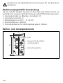
Bedien- und Anzeigeelemente
SEITE 2
45
83
LEDs
4 Buchsen M12
Beschriftungsfelder
Fixierung für IR-Adapter

SEITE 3
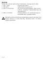
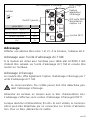
Adressieren
Vergeben Sie eine freie Adresse zwischen 1 und 31, Auslieferungs-
adresse ist 0.
Adressieren mit dem Adressiergerät AC1144
In Verbindung mit dem FK-Unterteil AC5000 muß das Modul erst über
das Adressiergerät AC1144 adressiert und dann montiert werden.
Infrarot-Adressierung
Das AS-i Modul bietet zusätzlich die Möglichkeit zur Infrarot-Adressie-
rung mit dem Adressiergerät AC1144.
Die AS-i Kommunikation (gelbes Kabel) muß während der Infra-
rot-Adressierung abgeschaltet sein.
Versorgen Sie die Slaves über das AS-i Netzteil mit Spannung. Die
Adressierung erfolgt über das IR-Adressierkabel E70211.
Bei Verwendung von ifm AS-i Netzteilen SL kann die Kommunikation
über einen Stecker am Netzteil deaktiviert werden. Klemmen Sie dafür
den Master ab.
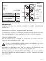
4x LED1 gelb
LED2 rot
FAULT
LED grün
PWR
Spannungs-
versorgung
o.k
4 Buchsen
M12
Eingänge
1
34
2
n.c.
M12-Buchse Pin
1
Sensorversorgung L- 3
Dateneingang I 2+4
n.c. 5
Sensorversorgung L+
Fixierung
IR-Adapter
LED Infrarot-Empfänger

Betrieb
Prüfen Sie, ob das Gerät sicher funktioniert. Anzeige durch LEDs:
•LED 1 gelb: Eingang geschaltet
•LED grün: Spannungsversorgung o.k.
•LED 2 rot leuchtet: AS-i Kommunikationsfehler, Slave nimmt
nicht am „normalen“ Datenverkehr teil, z. B.
Slaveadresse 0
•LED 2 rot blinkt: Peripheriefehler, z. B. Sensorversorgung
überlastet bzw. kurzgeschlossen
Überlast und Kurzschluß der Eingangsversorgung wird dem AS-i
Master (Version 2.1) über das Flag „Periphery Fault“ im Status-
register signalisiert.
SEITE 4

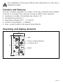
For installation and set-up follow the instructions on the use in
hazardous areas.
Function and features
The AS-i module operates as a slave in the AS-i network (AS-i profile:
S-0.0.E). It connects four sensors (2-wire or PNP 3-wire sensors).
•maximum number of modules per master: 31
•AS-interface version 2.1
•operating voltage 26.5 ... 31.6V DC
•current consumption < 240mA
•max. current load for all inputs total 200mA
Operating and display elements
PAGE 5
45
83
LEDs
4 sockets M12
labels
fixture infrared adapter

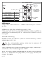
Addressing
Assign a free address between 1 and 31. At the factory the address is
set to 0.
Addressing with the adressing unit AC1144
If it is used with the FC lower part AC5000 the module must first be
addressed via the addressing unit AC1144 and then mounted onto the
lower part.
Infrared addressing
The AS-i module also offers the option of infrared addressing with the
addressing unit AC1144.
The AS-i communication (yellow cable) must be switched off
during the infrared addressing.
Supply the slaves with voltage via the AS-i power supply. Addressing is
carried out via the IR addressing cable E70211.
When the ifm AS-i power supplies type SL are used the communica-
tion can be deactivated via a plug on the power supply. To do so, dis-
connect the master.
PAGE 6
4x LED1 yellow
LED2 red FAULT
LED green
PWR sensor
supply o.k
4 sockets
M12
inputs
1
34
2
n.c.
socket M12 pin
1
sensor supply L- 3
data input I 2+4
not connected 5
sensor supply L+
fixture
infrared
adapter
LED infrared reciever

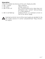
Operation
Check the reliable functioning of the unit. Display by LEDs:
•LED 1 yellow: input switched
•LED green: voltage supply o.k.
•LED 2 red is lit: AS-i communication error, slave does not
participate in the “normal” data exchange,
e. g. slave address 0
•LED 2 red flashing: peripheral fault, e.g. overload or short cir-
cuit of the sensor supply
Overload and short circuit of the input supply are signalled to the
AS-i master (version 2.1) via the "peripheral fault" flag in the sta-
tus register.
PAGE 7

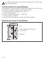
Lors de la mise en service suivre les instructions sur l'emploi dans
les zones explosives.
Fonctionnement et caractéristiques
Ce module est un esclave dans le réseau AS-i (Profil AS-i S-0.0.E). Il rac-
corde quatre capteurs (capteurs 2 fils ou PNP 3 fils).
•nombre maximal de modules par maître: 31
•version AS-interface 2.1
•tension d'alimentation 26,5 ... 31,6V DC
•consommation < 240mA
•courant de sortie total pour toutes les entrées 200mA
Eléments de service et d’indication
PAGE 8
45
83
LED
4 prises M12
étiquettes
fixation adaptateur infrarouge

Adressage
Affecter une adresse libre entre 1 et 31. A la livraison, l'adresse est 0.
Adressage avec l'unité d'adressage AC1144
Si le module est utilisé avec l'embase pour câble plat AC5000 il doit
d'abord être adressé via l'unité d'adressage AC1144 et ensuite être
monté sur l'embase.
Adressage infrarouge
Le module AS-i offre également l'option d'adressage infrarouge par l’
unité d'adressage AC1144.
La communication AS-i (câble jaune) doit être désactivée pen-
dant l'adressage infrarouge.
Alimenter les esclaves en tension avec le bloc d'alimentation AS-i.
L'adressage s'effectue via le cordon d'adressage infrarouge E70211.
Lorsque des blocs d'alimentation ifm AS-i SL sont utilisés, la communi-
cation peut être désactivée par un connecteur sur le bloc d'alimenta-
tion. Pour ce faire, débrancher le maître.
PAGE 9
4x LED1 jaunes
LED2 rouge
FAULT
LED verte PWR
alimentation
capteur o.k
4 prises M12
entrées
1
34
2
n.c.
prise M12 broche
1
alimentation capteur L- 3
entrée donnée I 2+4
n.c. 5
alimentation capteur L+
fixation
adaptateur
infrarouge
LED récepteur infrarouge

Fonctionnement
Vérifier le bon fonctionnement du module. Affichage par LED:
•LED jaune: entrées commutées
•LED verte: alimentation o.k.
•LED 2 rouge allumée: erreur de communication AS-i, esclave ne
participe pas à l'échange "normal" des
données, p. ex. adresse d'esclave 0
•LED 2 rouge clignote: défaut périphérique, p.ex. surcharge ou
court-circuit de l'alimentation des capteurs
La surcharge et le court-circuit de l'alimentation des entrées sont
signalisés au maître AS-i (version 2.1) via le bit interne "défaut
périphérique" dans le registre d'états.
PAGE 10
-
 1
1
-
 2
2
-
 3
3
-
 4
4
-
 5
5
-
 6
6
-
 7
7
-
 8
8
-
 9
9
-
 10
10


dans d''autres langues
- English: IFM AC005A Installation guide
- Deutsch: IFM AC005A Installationsanleitung
Documents connexes
Autres documents
-
SICK UE4215 AS-interface Safetyat Work Safe Busnode Mode d'emploi
-
-
Camille Bauer EMMOD 206 Manuel utilisateur
-
Pepperl+Fuchs VBA-8E8A8A-KE4-ZEL/E2L/SEL Mode d'emploi
-
Gossen MetraWatt METRAHit ASi V3.0 Mode d'emploi
-
Festo ASI-MV-4A-Z Brief description
-
Asco Series 569 570 571 BUSLINK Generation C Le manuel du propriétaire