Jandy JVA 2444 Guide d'installation
- Catégorie
- Accessoires de piscine hors terre
- Taper
- Guide d'installation

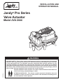
Jandy® Pro Series
Valve Actuator
Model JVA 2444
H0570800 Rev J
INSTALLATION AND
OPERATION MANUAL
WARNING
FOR YOUR SAFETY - This product must be installed and serviced by a contractor who is licensed and
qualified in pool equipment by the jurisdiction in which the product will be installed where such state
or local requirements exist. The maintainer must be a professional with sufficient experience in pool
equipment installation and maintenance so that all of the instructions in this manual can be followed
exactly. Before installing this product, read and follow all warning notices and instructions that accompany
this product. Failure to follow warning notices and instructions may result in property damage, personal
injury, or death. Improper installation and/or operation will void the warranty.
Improper installation and/or operation can create unwanted electrical hazard which can
cause serious injury, property damage, or death.
ATTENTION INSTALLER - This manual contains important information about the
installation, operation and safe use of this product. This information should be given to
the owner/operator of this equipment.

DATE OF INSTALLATION
INSTALLER INFORMATION
INITIAL PRESSURE GAUGE READING (WITH CLEAN FILTER)
PUMP MODEL HORSEPOWER
FILTER MODEL SERIAL NUMBER
CONTROL PANEL MODEL SERIAL NUMBER
NOTES:
EQUIPMENT INFORMATION RECORD
Page 2 ENGLISH Jandy® Pro Series Valve Actuator | Installation and Operation Manual

Table of Contents
Section 1. Safety Information .......................... 4
Section 2. General Information ....................... 5
2.1 Introduction ......................................................... 5
2.2 Description ......................................................... 5
Section 3. JVA Mounting Positions ................. 5
3.1 Standard JVA Position ........................................ 5
3.2 Actuator Mounting .............................................. 6
Section 4. Synchronization .............................. 7
4.1 Synchronization Methods ................................... 7
4.2 Resetting the Cams ............................................ 7
Section 5. Manual Operation ........................... 9
5.1 Manual Override ................................................. 9
5.2 Manual Override, Power On ............................... 9
5.3 Manual Override, Power Off ............................... 9
Section 6. Maintenance .................................. 10
6.1 Actuator ............................................................ 10
6.2 Valve ................................................................. 10
Section 7. Wiring Diagrams ..............................11
7.1 JVA Wiring Schematic 2444 ..............................11
7.2 JVA's with Toggle Switch ...................................11
7.3 JVA's with Time Clock .......................................11
Section 8. Troubleshooting ............................. 12
8.1 Troubleshooting ................................................ 12
Section 9. JVA Exploded View
and Spare Parts ............................ 13
Page 3
ENGLISH
Jandy® Pro Series Valve Actuator | Installation and Operation Manual

Section 1. Safety Information
IMPORTANT SAFETY INSTRUCTIONS PERTAINING TO A RISK OF FIRE,
ELECTRIC SHOCK, OR INJURY TO PERSONS
READ AND FOLLOW ALL INSTRUCTIONS
When installing and using this electrical equipment, basic safety precautions should always be followed, including the
following:
SAVE THESE INSTRUCTIONS
WARNING
This manual contains important information about the installation, operation and safe use of this product. This
information should be given to the owner/operator of this equipment.
WARNING
This product must be installed and serviced by professionals who are qualified in pool/spa product installation and
service. Improper installation and/or operation can create an unwanted electrical hazard which can cause serious
injury, property damage, or death. Improper installation and/or operation will void the warranty.
WARNING
Disconnect power to the system at the main circuit breaker before servicing to avoid risk of electric shock which can
result in property damage, severe injury or death. All wiring must be done in accordance with the National Electrical
Code® (NEC®), NFPA-70. In Canada, all wiring must be done in accordance with the Canadian Electrical Code
(CSA C22.1). All applicable local installation codes and regulations must be followed.
Page 4 ENGLISH Jandy® Pro Series Valve Actuator | Installation and Operation Manual

Section 2. General Information
2.1 Introduction
This manual contains information for the proper
installation and operation of Jandy® Pro Series Valve
Actuators (JVA). Procedures in this manual must be
followed exactly. To obtain additional copies of this
manual visit www.zodiacpoolsystems.com. For address
information, see back cover.
2.2 Description
Valve Actuators are designed to meet the needs of
today's more advanced, automatic pool equipment.
These fully adjustable actuators offer versatile pool/spa
automation with easy setups. All actuators work with
AquaLink® RS Control Systems and are available in 24
volt units.
JVA 2444 Specifications
Voltage 24 VAC
Amperage 0.75 AMPS
Cycles 60 Hz
Wire
Black
Red
White
3-conductor
Common
Switch Leg
Switch Leg
Figure 2. Standard JVA Mounting
A
B (Common Port)
C
A
B (Common Port)
C
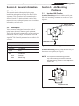
Figure 1. Standard Plumbing
Water ow into or
out of the valve
Remove these
four (4) screws for
Standard Position
Section 3. JVA Mounting
Positions
3.1 Standard JVA Position
Standard Plumbing position is with the middle port
(B) as the incoming or common port to the valve (see
Figure 1).
Standard Mounting position is with the main body of
the actuator over port B (see Figure 2).
NOTE If the valve(s) are plumbed with port B as the
common port (Standard Plumbing) and the main
body of the actuator(s) are mounted over port B
(Standard Mounting), there is no need to adjust the
actuator cams.
Page 5
ENGLISH
Jandy® Pro Series Valve Actuator | Installation and Operation Manual

3.2 Actuator Mounting
JVA’s mount directly on all full-size Jandy Pro
Series Valves (8 screws on lid). Zodiac recommends
motorizing Jandy Pro Series Never Lube® Valves only.
JVA’s may be mounted onto valves in any of the four (4)
positions in Figure 3.
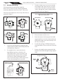
A
Figure 3. JVA Mounting Positions.
B
C
A
B
C
III
III
IV
A
A
B
B
C
C
1.
Unscrew the locking knob by turning the knob
counterclockwise. Remove the locking knob and
valve handle (see Figure 4).
2. For standard valves, remove the four (4)
large Phillips head screws from the valve.
The location of the screws you remove will
determine how the actuator will be mounted
(see Figure 4). When installing the large 3"
valve, it is not necessary to remove any screws.
Use the four mounting bosses provided.
Figure 4. Remove Locking Knob and Lid Screws
Remove Locking
Knob and Handle
Remove the 4 Large
Phillips Head Screws
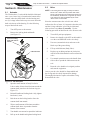
3. Turn the actuator over so you can see into the
clear actuator shaft. There are four (4) "teeth"
on the inside of the shaft. Locate the smallest
"tooth" and align this "tooth" with the smallest
slot on the valve (see Figure 5).
Figure 5. Actuator Mounting
Place actuator on valve so smallest tooth
aligns with smallest slot.
Smallest Slot
Actuator
Bottom
Smallest Tooth
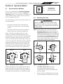
4. Place the actuator onto the valve.
5.
Rotate the actuator while keeping the two shafts
engaged until the screw holes on the actuator legs
align with the empty screw holes (from step 2) in
the valve (see Figure 6).
6. Use the four (4) large 2" Phillips head screws
(included with the JVA) to secure the JVA to the
valve.
7. Put the valve handle on the actuator shaft. Put
the knob on the shaft and tighten (nger tighten
only).
Figure 6. Actuator Mounting
Rotate valve or actuator
to align screw holes
Rotate
valve
Rotate
actuator
Page 6 ENGLISH Jandy® Pro Series Valve Actuator | Installation and Operation Manual

Figure 8. JVA Synchronization, Toggle
ON 1
OFF
ON 2
On/Off Switch is
located on the
bottom of the JVA
4.2 Resetting the Cams
WARNING
Improper cam settings can result in dead heading
of the water flow which can cause injury or property
damage. Improper cam settings and/or operation will
void the warranty.
NOTE Before resetting cams, if the valve is plumbed in
Standard Plumbing position and the actuator is in
Standard Mounting position there is no need for
resetting the cams (see Figure 9). If a port other than
"B" is plumbed as the common port or if the actuator
is mounted other than Standard Mounting, the cam
setting must be changed so the actuator shaft and
the valve diverter rotate properly. Refer to the Cam
Setting Chart on page 8 for proper settings.
Figure 9. JVA Mounting Positions.
A
B
C
II
A
B
I
C
C
III
A
B
IV
A
B
C
1. Turn OFF actuator power. Unscrew
the locking knob by turning the knob
counterclockwise. Remove the locking knob
and valve handle.
2. Remove the four (4) Phillips head screws that
secure the actuator lid and then remove the lid.
Section 4. Synchronization
4.1 Synchronization Methods
If the valve is plumbed in the Standard Plumbing
position and the actuator is mounted in Standard
Mounting position, you do not have to change the cam
settings from the factory settings. However, you may
have to synchronize the cams.
One of the following will occur when the actuator is out
of synchronization:
• the actuator will rotate in the wrong direction
in relation to its controller (as in a solar heating
system)
• one actuator will rotate incorrectly in relation to
another actuator (as in pool/spa combination)
Figure 7 illustrates an example of the valves and
actuators of a pool/spa combination that are out of
synchronization. The valve on the left of the illustration
(suction) is plumbed with the spa line on the left side
of the valve and the pool line on the right; whereas, the
valve on the right of the illustration (return) is plumbed
with the pool on the left side of the valve and the spa
on the right. In this conguration, if the actuators are
activated, one will turn to spa while the other will turn
to pool. The actuators will have to be synchronized.
Figure 7. JVA Synchronization, Example
Suction Return
Spa SpaPoolPool
On the actuator that is out of synchronization, ip the
toggle switch located on the bottom of the actuator to
the ON 2 position (see Figure 8). The toggle positions
are marked on the actuator top cover. Retry the system.
Page 7
ENGLISH
Jandy® Pro Series Valve Actuator | Installation and Operation Manual

NOTE The cam is marked with the arrow at "0", a long hash
mark at the 180° position, and 2 short hash marks at
the 90° and 270° positions.
4. To set the cams, rotate the cam(s) until the
arrow mark on the cam(s) align with the
microswitch actuator (see Figure 11).
NOTE The upper cam stops counterclockwise rotation and
the lower cam stops clockwise rotation.
5. Turn power ON to the actuator and use the
toggle switch located on the bottom of the
actuator to check rotation. Move the toggle
switch to either ON 1 or ON 2. Allow the
actuator shaft to move until it stops. Check
valve diverter position*, if the position is
correct ip the toggle switch in the opposite
direction and allow the shaft to stop again. If
the stop positions are correct, go to step 6. If
they are not, reset the cams until correct.
NOTE If the actuator does not move in either direction, refer
to Section 6, Troubleshooting.
6. Replace the lid and tighten screws. Replace the
handle and locking knob.
NOTE The end of the handle which has the word OFF
embossed on it exactly duplicates the shape of the
valve diverter. When the handle is placed on a valve
or actuator shaft the word OFF will be directly over
the center of the valve diverter.
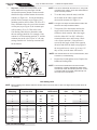
Cam Setting Chart
NOTE Before resetting cams, always rotate the actuator shaft so the arrow mark on each cam aligns with the pointer above its
microswitch.
Actuator
Mounting
Water Enters Port
Common Port
Cam Setting
Top Cam Bottom Cam
Water Exits Valve
Port or Port
*I A 90 180 B C
I B 90 270 A C
I C 180 90 A B
*II A 180 90 B C
II B 0 0 A C
II C 90 180 A B
*III A 90 180 B C
III B 270 90 A C
III C 0 270 A B
*IV A 0 270 B C
IV B 180 180 A C
IV C 270 0 A B
*Two Port Valve Settings
3. Important - Rotate the actuator shaft so the
arrow mark on the top cam aligns with the
microswitch actuator (bottom cam arrow mark
should also align with the bottom microswitch
actuator, see Figure 10). Locate the mounting
position for the actuator (as per Figure 9, the
mounting position will be either I, II, III, or IV).
Next, determine what valve port is the common
or inlet port (as per Figure 9, the common port
will be either A, B, or C). Then refer to the
Cam Setting Chart below to determine what
the cam settings should be. For example, if the
actuator is in JVA mounting position "I", and the
common port on the valve is port "A", the cam
settings would be 90° for the top cam and 180°
for the bottom.
Figure 10. JVA Cams
0
0
Right
Microswitch
Left
Microswitch
Upper
Cam
Lower
Cam
Final minor adjustments may be necessary
0°
180°
270°
90°
Page 8 ENGLISH Jandy® Pro Series Valve Actuator | Installation and Operation Manual

Figure 11. JVA Cam Adjustment
Rotate Cams
Section 5. Manual Operation
5.1 Manual Override
It is sometimes necessary to rotate valve(s) manually,
without using the system controller. This occurs when
the controller is not accessible/operational or when the
spa or pool/spa combination require lling or draining.
There are two (2) methods of manually rotating the
JVA; one with power on (system operational) and one
with power off (no power to the control system).
CAUTION
To prevent damage to your equipment and to
minimize the possibility of any injury resulting from
such damage, make sure that the pool ltration pump
is OFF BEFORE rotating the valve handle.
5.2 Manual Override, Power On
1. Move the toggle switch located on the bottom
of the actuator to the opposite position (ON 1
switch to ON 2 or vice versa). This will rotate
the motor to the opposite position.
2. Return the toggle switch to the original position
after use.
ON 1
OFF
ON 2
Figure 12. JVA Synchronization, Toggle
On/Off Switch is
on Bottom of JVA
5.3 Manual Override, Power Off
1. Move toggle switch located on the bottom of
actuator to the OFF (center) position.
2. Unscrew (counterclockwise) the locking knob
above the handle four (4) full turns.
3. Push down on the locking knob (not the
handle). This will disengage the gear train and
allow the handle, and thus the valve diverter, to
be moved to any position.
4. To return the actuator to automatic position, pull
up on the handle while turning it clockwise or
counterclockwise until you feel the shaft slide
up into the gear train. Turn the locking knob
down (clockwise) until snug.
5. Put toggle switch back to the original position.
Page 9
ENGLISH
Jandy® Pro Series Valve Actuator | Installation and Operation Manual

Section 6. Maintenance
6.1 Actuator
The JVA has three (3) seals which should be lubricated
once a year. One o-ring is located on the bottom of the
actuator where the plastic shaft exits the housing and
two (2) O-rings located in the top cover near where the
shaft exits the top of the housing. Use the following
steps to lubricate the seals:
1. Turn OFF power to the actuator.
2. Remove the locking knob and handle
(see Figure 13).
Figure 13. JVA Shaft Seal
Lubricate here
Unscrew locking
knob and remove
handle
3. Spread a small amount of Jandy Pro Series
Lube or other silicone base lubricant around the
actuator shaft just above the lock out ring (see
Figure 13).
4. Reinstall handle and locking knob. Only tighten
knob one (1) turn.
5. Push down on the locking knob to force the
actuator shaft into manual.
6. Wipe a small amount of lubricant around the
actuator shaft where it protrudes from the
bottom of the actuator.
7. Turn handle once around to spread the lubricant.
8. Pull up on the handle and tighten locking knob.
6.2 Valve
NOTE This section does not apply to Jandy Pro Series
Never Lube® Valves and non-positive seal valves.
Never Lube Valves and non-positive seal valves can
be identified by the absence of a grease cap. Never
Lube Valves can also be identified by the name
"Never Lube" on the handle.
Since the actuator rotates the valve diverter which
redirects the ow of water, it is imperative that the seals
and the O-rings within the valve body be lubricated
often (at least every three (3) months). Use the
following procedure to lubricate the valve diverter seals:
1. Turn off all pool/spa equipment.
2. Rotate valve handle so the OFF on the handle is
over the word GREASE on the valve body.
3. Unscrew (counterclockwise) and remove the
black cap of the grease tting.
4. Fill cap with lubricant (Jandy Lube).
5. Replace cap on tting and turn in (clockwise)
until all of the lubricant has been forced into the
valve.
6. Use manual operation to move the handle from
side to side to spread the lubricant across the
seal.
7. Reset the valve handle to its original position
and start the equipment.
Once a year the valve should be disassembled and
the O-ring and valve body inspected for damage.
Thoroughly lubricate the square seal and the O-ring.
Reassemble the valve.
Page 10 ENGLISH Jandy® Pro Series Valve Actuator | Installation and Operation Manual

Section 7. Wiring Diagrams
7.1 JVA Wiring Schematic 2444
WARNING
Disconnect power to the system at the main circuit
breaker before servicing to avoid risk of electric shock
which can result in property damage, severe injury
or death. All wiring must be done in accordance with
the National Electrical Code® (NEC®), NFPA-70.
In Canada, all wiring must be done in accordance
with the Canadian Electrical Code (CSA C22.1). All
applicable local installation codes and regulations
must be followed.
CAUTION
To avoid damage to the equipment and minimize
risk of injury, use a properly sized, listed Class 2
transformer for connection to the power supply.
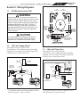
7.2 JVA's with Toggle Switch
This diagram is for two (2) JVA 2444s.
To operate more JVA's, additional poles and a higher
amperage fuse are needed. Do not double lug the JVA
switch leg wires (red and white wires).
* Transformer must be sized for the number of JVA's.
Each JVA requires .75 amp. at 24 VAC.
7.3 JVA's with Time Clock
This diagram is for a single JVA 2444.
To operate more JVA's, additional poles and a higher
amperage fuse are needed. Do not double lug the JVA
switch leg wires (red and white wires).
* Transformer must be sized for the number of JVA's.
Each JVA requires .75 amp. at 24 VAC.
RED
WHITE
BLACK
OFF
Normally Closed
Normally Open
Common
1amp
fuse 120 VAC
Transformer*
Secondary
(24 VAC)
Primary
(120 VAC)
Single Pole/
Double Throw
Relay
Coil Voltage: 120 VAC
Neutral
Line
Load
Time
Clock
Neutral
Hot
Left
Micro switch
Right
Micro switch
Common Common
NO NO
NC NC
Red
Red
Bottom Cam
Motor
Connector
to PCB
Header
Top Cam
Motor
Connector
to PCB
Header
Black
Black
Black
Red
White
White
White
White
White
POWER
Red
Red
Black
Wiring to Toggle
Switch Underneath
Circuit Board
PCB Header for Motor Wiring
OFF
RED
WHITE
BLACK
WHITE
BLACK
OFF
Normally Closed
Normally Open
Common
2amp
fuse
RED
120 VA C
Transformer*
Secondary
(24 VAC)
Primary
(120 VAC)
Double Pole/
Double Throw
Toggle Switch
Page 11
ENGLISH
Jandy® Pro Series Valve Actuator | Installation and Operation Manual

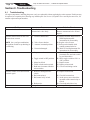
Section 8. Troubleshooting
8.1 Troubleshooting
All major components, including the power cord, are replaceable without replacing the entire actuator. Each item may
be replaced as a separate piece allowing easy ineld repair. See Section 8, Exploded Views and Replacement Kits, for
actuator replacement part numbers.
Problem Cause Solution/Check
Actuator handle oscillates. Lack of valve seal lubrication.
Obstruction in valve body.
Lubricate valve.
Remove actuator and valve lid and
inspect.
Actuator motor works but the valve
diverter does not turn.
NOTE On a pool/spa combination,
the problem would be spa draining or
overowing.
A). Actuator shaft broken.
B). Valve diverter broken.
C). Actuator in manual position.
D). Gear train damaged.
A). Replace actuator shaft. Refer to
Shaft Replacement Kit
instructions for disassembly.
B). Replace valve diverter.
C). Pull up on the handle while
rotating counterclockwise.
D). Refer to Gear Replacement Kit
instructions for disassembly.
Actuator motor does not turn. A) No power to the actuator.
B) Toggle switch in OFF position.
C) Motor has failed.
D) Failed or broken microswitch.
E) Both cams in contact with their
microswitches.
A) Check voltage between black
(common) wire and each switch
leg (red then white)
B) Move toggle switch to ON 1 or
ON 2 position.
C) Replace motor.
D) Replace microswitch.
E) Check Cam Setting section.
Actuator rotates in one direction but
not back again.
A) Broken or damaged micro-
switch.
B) Bad connection(s).
C) Bad control relay switch.
D) Broken wire.
A) Replace microswitch.
B) Check all connections.
C) At the power source check the
operation of the control relay or
switch.
D) Check red and white wires.
Water inside valve actuator. Damaged seals. Replace top lid and grease seals.
Page 12 ENGLISH Jandy® Pro Series Valve Actuator | Installation and Operation Manual

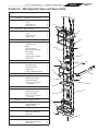
Section 9. JVA Exploded View and Spare Parts
Dwg.
#
Kit # Description Qty.
1 R0409600 JVA Gasket and Screw Kit
Gasket
O-ring,
Screw, #14 x 2"
Screw, #8 x 5/8"
1
2
4
4
2 R0411500 Top Housing Kit
Gasket
O-ring
Screw, #8 x 5/8"
Housing, Top
1
2
4
1
3 R0408700 Center Plate Kit
O-ring
Screw, #8 x 5/8"
Bridge
Top Cam (Clear)
Bottom Cam (Textured)
Microswitch
Center Plate
Output Shaft, Threaded
Spring, JVA
2
8
1
1
1
2
1
1
1
4 R0411600 Gear Kit
Primary Gear
Secondary Gear
Large Pinion Gear
Output Gear
Housing, Bottom w/3 Pins
1
1
1
1
1
5 R0411800 Cable Kit, 20'
O-ring, Strain Relief
Washer, Strain Relief
Cap, Strain Relief
Power Cord, 20' w/3-pin
Connector
1
1
1
1
5 R0411900 Cable Kit, 75'
O-ring, Strain Relief
Washer, Strain Relief
Cap, Strain Relief
Power Cord, 75' w/3-pin
Connector
1
1
1
1
6 R0441700 PCB w/Toggle Switch Kit
PCB Sub-Assy, 24V w/PCB,
w/Toggle Switch, Lock
Washer and Nut
1
7 R0408500 Motor Kit
Screw, #8 x 5/8"
Motor 24V, w/Wire and
Connector
1
1
8 R0408600 Cam and Microswitch Kit
Top Cam (Clear)
Bottom Cam (Textured)
Microswitch
1
1
2
1
1, 2
2
1, 2
1, 2, 3 3
3, 7
3
7
6
3
3
4
4
3
3
3
3,8
5
3, 8
6
Page 13
ENGLISH
Jandy® Pro Series Valve Actuator | Installation and Operation Manual

NOTES
Page 14 ENGLISH Jandy® Pro Series Valve Actuator | Installation and Operation Manual

NOTES
Page 15
ENGLISH
Jandy® Pro Series Valve Actuator | Installation and Operation Manual

Zodiac Group Australia.
219 Woodpark Road
Smithfield, NSW AU 2164
1.800.688.552 | www.Zodiac.com.au
Zodiac Pool Systems, Inc.
2620 Commerce Way, Vista, CA 92081
1.800.822.7933 | www.ZodiacPoolSystems.com
©2016 Zodiac Pool Systems, Inc. ZODIAC® is a registered trademark of Zodiac International,
S.A.S.U., used under license. All trademarks referenced herein are the property of their respective
owners.
H0570800 Rev J
ETL LISTED CONFORMS TO
UL-STD 1563
CERTIFIED TO CAN/CSA C22.2 NO.218.1

USA & Canada
Jandy Limited Warranty
États-Unis et Canada
Garantie limitée Jandy
EE.UU. y Canadá
Garantía limitada de Jandy
To ensure best customer service and tracking of warranty,
we recommend you register your product at:
Jandy.com/Registration (USA)
Jandy.ca/Registration (Canada)
Pour bénéficier du meilleur service à la clientèle et du suivi de la garantie,
nous vous recommandons d’enregistrer votre achat ici :
Jandy.com/Registration (USA)
Jandy.ca/Registration (Canada)
Para asegurar el mejor servicio al cliente y el rastreo de la garantía,
recomendamos que registre su producto en:
Jandy.com/Registration (USA)
Jandy.ca/Registration (Canada)

JANDY LIMITED WARRANTY
Zodiac Pool Systems LLC, a Fluidra Company (“Fluidra”) warrants all Jandy® branded products to be free from manufacturing defects in materials and workmanship for a period of one (1) year
from the date of retail purchase, with the exceptions listed below.
1. Variable speed pumps are warranted for three (3) years.
2. JXi™ heaters are warranted for one (1) year. Heat Exchangers on JXi Gas Heaters with factory-installed VersaFlo™ Integrated Bypass are warranted for five (5) years.
3. Heat pumps are warranted for two (2) years. Heat pump compressors and heat exchangers are warranted for five (5) years.
4. Nicheless underwater lights are warranted for three (3) years.
5. Complete electronic salt water chlorine systems (controller and cell purchased and installed together) are warranted for three (3) years.
6. Those certain Never Lube® valves made from CPVC are warranted for the life of the pool on which they were originally installed. For the avoidance of any doubt, any Never Lube valve made
from PVC is only warranted to be free from manufacturing defects in materials and workmanship for a period of one (1) year from the date of retail purchase.
7. Refrigerant and other expendables are not warranted.
8. Replacement products, or parts, provided at no charge are warranted only until the original finished good’s warranty has expired. Purchased replacement parts are warranted for ninety (90)
days from the date of retail purchase, with the exception of electronic salt water chlorine generator cells and electrodes, which are warranted for one (1) year.
9. Maintenance tools are warranted for ninety (90) days.
10. All Jandy branded products used in a commercial application are warranted for a period of one (1) year from the date of retail purchase, unless a lesser amount of time is stated above in
exceptions 1 through 9. A commercial application is defined as any application other than a single-family dwelling.
This Jandy Limited Warranty does not apply to Jandy branded products purchased through the Internet or other e-commerce platforms, with the exception of Jandy branded
valves less than three (3) inches in diameter, parts, and pool product accessories.
This warranty applies only to products installed and serviced by a contractor who is licensed and qualified in pool equipment by the jurisdiction in which the product will be installed,
where such state or local requirements exists. In the event no such state or local requirement exists, the installer and maintainer must be a professional with sufficient experience in pool
equipment installation and maintenance. This warranty applies only to products purchased and utilized in the 50 United States and Canada, is limited to the first retail purchaser, is not transferable,
and does not apply to products that have been moved from their original installation sites. The liability of Fluidra shall not exceed the replacement of the defective product or its parts, and does
not include transportation costs, costs for labor to service or repair the defective product, or any items or materials required to make the repair including, but not limited to, refrigerant and other
expendables. Fluidra is not responsible for charges or delays incurred when a servicer is unable to perform service due to lock outs, animals, intolerable pool or spa water temperature when entry
into pool or spa is required to perform service, service refusals, etc. No reimbursements will be made for loss and/or usage of water, fuel or other resources resulting from product defect. A third
party service provider may charge the end-user customer for parts and/or labor required to resolve any issue not covered under warranty, such as improper installation. Fluidra is not responsible
for these charges. Product discoloration, or any other cosmetic or superficial damage or deterioration, regardless of its cause, is not covered by this warranty. This warranty does not cover failures,
defects, malfunctions or complaints resulting from any of the following:
1. Failure to properly install, operate or maintain the product in accordance with Fluidra’s published installation, operation and/or maintenance manuals.
2. Improper equipment sizing or product mis-applications.
3. The workmanship of any installer of the product.
4. Use of non-factory authorized parts or accessories in conjunction with the product(s).
5. Product modifications or adjustments that are not in accordance with Fluidra’s published installation, operation and/or maintenance manuals.
6. Not maintaining proper pool and/or spa chemical balance [pH levels between 7.2 and 7.8, with ideal range being between 7.4 and 7.6; Cyanuric Acid
(CYA) between 30 to 100 ppm; Total Alkalinity (TA) between 80 to 120 ppm (100 to 150 ppm for vinyl pools); Total Dissolved Solids (TDS) less than 1500 ppm, not including salt ppm; and
Total (or Calcium) Hardness less than 800 ppm, with an ideal range being between 200 ppm and 400 ppm].
7. Corrosion, erosion, scaling, calcification or other conditions caused by water hardness, chemical imbalance, or lack of product maintenance.
8. Chemical contamination of combustion air; or improper use of pool/spa chemicals, such as introducing chemicals upstream of the heater or cleaner hose, or through the skimmer; or use of
copper-based algaecides in conjunction with Nature2 products.
9. Abuse, damage during transit or installation, mis-handling, tampering, vandalism, alterations, accidents, fires, floods, storms, earthquakes, power surges, lightning, pets or other animals,
insects and/or their hives or nests, negligence, or acts of God.
10. Not grounding and/or bonding as specified, mis-wiring, loose wiring, cut or kinked wires, loose cable connections, incorrect wire runs, incorrect breaker size, breaker(s) in “off” position,
improper wire gauge, moisture in electrical conduit, improper electrical supply, dead batteries, incorrect plumbing, inadequate size of pipe and/or fittings, cross-threading, over-tightening,
under-tightening, glue drips or residue, improperly secured covers, improper valve placement or usage, unsynchronized valve actuators, valve actuators in “off” position, improper gas pipe
sizing, lack of fuel, or inadequate heater vent pipe sizing, programming errors.
11. Freezing, corrosion, cracking, overheating, warping, flooding, moisture intrusion or any other condition caused by or related to weather, climate, improper winterization, improper equipment
placement, inadequate ventilation, inadequate water circulation, roof run-off, sprinklers, irrigation systems, or lights or other products on or near the pool/spa or pool/spa equipment pad.
12. Operating the product at water flow rates below minimum, or above maximum, specifications. Operating any product or piece of equipment including, but not limited to, pumps, with
insufficient quantities of water.
13. Dirty, clogged, blocked, covered or obstructed plumbing, chlorine generator cells or sensors, pump strainer baskets, pump impellers, heater orifices
(including blockage by spider webs), heater grills, doors, flue boxes, flue vents or flue collectors, filter elements, or filter breather tubes.
14. Collateral damage caused by failure of any component including O-rings, pump strainer baskets, DE grids, sand filter laterals, or cartridge elements.
This is the only warranty given by Fluidra. No one is authorized to make any other warranties on behalf of Fluidra. THE DURATION OF IMPLIED WARRANTIES, INCLUDING THE IMPLIED
WARRANTY OF MERCHANTABILITY AND THE IMPLIED WARRANTY OF FITNESS FOR A PARTICULAR PURPOSE, ARE LIMITED TO THE DURATION OF THE EXPRESS WARRANTIES LISTED
ABOVE. Some states and/or provinces do not allow limitations on how long an implied warranty lasts, so the above limitation may not apply to you. Fluidra expressly disclaims and excludes any
liability for consequential, incidental, indirect, or punitive damages for breach of any expressed or implied warranty. In no event shall Fluidra be liable for incidental or consequential damages of
any nature, including damage to vinyl liners, plaster, aggregate-based pool surfaces, tile, stone, coping, fixtures, skimmers or skimmer covers, plumbing, drains, equipment covers or shelters,
landscaping, animals, plants, or dwellings. Some states and/or provinces do not allow the exclusion or limitation of incidental or consequential damages, so the above limitation may not apply
to you. Certain vinyl liner patterns are particularly susceptible to rapid surface wear or pattern removal caused by objects coming into contact with the vinyl surface, including pool brushes, pool
toys, floats, fountains, chlorine dispensers, and automatic pool cleaners. Some vinyl liner patterns can be seriously scratched or abraded by rubbing the surface with a pool brush. Ink from the
pattern can also rub off during the installation process or when it comes into contact with objects in the pool. Fluidra is not responsible for, and this warranty does not cover, pattern removal, cuts,
abrasions or markings on vinyl liners.
This warranty gives you specific legal rights. You may also have other rights that vary by state and/or province. For warranty consideration, contact the original dealer and provide the following
information: proof of purchase, model number, serial number, date of retail purchase, and date of installation. The dealer will contact the factory to obtain instructions regarding the claim and to
determine the location of the nearest independent service company. If the dealer is not available, you can locate an independent service company in your area by visiting www.fluidrausa.com or by
emailing our Technical Support Department at productsupport@fluidra.com, or by calling our Technical Support Department at 800-822-7933. All returned parts must have a Returned Material
Authorization number to be evaluated under the terms of this warranty.
GARANTIE LIMITÉE JANDY
Zodiac Pool Systems LLC (« Fluidra ») garantit que tous les produits de la marque Jandy® sont exempts de tout défaut de fabrication, de matériaux et de
main-d’œuvre pour une période d’un (1) an à compter de la date d’achat chez le détaillant, avec les exceptions suivantes :
1. Les pompes à vitesse variable sont garanties pendant trois (3) ans.
2. Les chauffe-eau JXiMC sont garantis pendant un (1) an. Les échangeurs de chaleur des chauffe-eau au gaz JXi dotés de la dérivation intégrée VersaFloMC sont garantis pendant cinq (5) ans.
3. Les thermopompes sont garanties pendant deux (2) ans. Les compresseurs et les échangeurs de chaleur de la thermopompe sont garantis pendant cinq (5) ans.
4. Les lampes immergées sans niche sont garanties pendant trois (3) ans.
5. Les systèmes électroniques complets de chlore à eau salée (régulateur et cellule achetés et installés ensemble), sont garantis pendant trois (3) ans.

6. Certaines valves Never Lube® fabriquées en PVC-C sont garanties pour la durée de vie de la piscine sur laquelle elles ont été installées à l’origine. Pour votre tranquillité d’esprit, toutes
les valves Never Lube® fabriquée en PVC-C sont garanties sans défaut de fabrication, de matériaux et de main-d’œuvre pour une période d’un (1) an à compter de la date d’achat chez le
détaillant.
7. Le réfrigérant et autres produits consommables ne sont pas couverts par la garantie.
8. La garantie sur les produits ou pièces de rechange fournis gratuitement prend fin à la date d’expiration de la garantie du produit fini d’origine. Les pièces de rechange achetées sont garanties
pendant quatre-vingt-dix (90) jours à compter de la date d’achat chez le détaillant, à l’exception des cellules et des électrodes du chlorateur électronique à eau salée, qui sont garanties
pendant un (1) an.
9. Les outils de maintenance sont garantis pendant quatre vingt dix (90) jours.
10. Tous les produits de marque Jandy utilisés dans une application commerciale sont garantis pour une période d’un (1) an à partir de la date d’achat au détail, à moins qu’une durée inférieure
ne soit indiquée plus haut dans les exceptions 1 à 9. Une application commerciale est définie comme toute application autre qu’une habitation unifamiliale.
La garantie limitée Jandy n’est pas valide pour les produits de la marque Jandy achetés sur l’Internet ou sur tout autre plateforme de commerce électronique, à l’exception des
valves, des pièces et des accessoires de marque Jandy.
Cette garantie est valide uniquement pour les produits installés et entretenus par un technicien agréé et qualifié pour la réparation des équipements de piscine par les autorités
compétentes du territoire où ledit produit est installé, lorsque de telles exigences locales ou provinciales existent. Si aucune exigence locale ou provinciale n’existe, la personne qui effectue
l’installation ou l’entretien doit être un professionnel possédant suffisamment d’expérience en matière d’installation et d’entretien des équipements de piscine. Cette garantie est valide uniquement
pour les produits achetés et utilisés dans les 50 états américains et au Canada. Elle est limitée au premier acheteur au détail, n’est pas transférable et ne s’applique pas aux produits qui ont été
déplacés de leur site d’installation d’origine. La responsabilité de Fluidra se limite au remplacement du produit ou des pièces défectueux et n’inclut pas les coûts de transport, de main-d’œuvre
pour réparer le produit défectueux, ni de tout autre matériel nécessaire pour faire la réparation, y compris mais sans s’y limiter, le réfrigérant et les autres produits consommables. Fluidra n’est pas
responsable des frais ou des retards encourus lorsqu’un technicien ne peut pas effectuer le service à cause d’un accès verrouillé, de la présence d’animaux, d’une température de l’eau intolérable
dans la piscine ou le spa, au cas où il serait nécessaire d’entrer dans la piscine ou le spa pour faire le service, des refus d’autoriser le service, etc. Aucun remboursement ne sera émis pour la
perte et/ou l’utilisation d’eau, de carburant ou d’autres ressources résultant des produits défectueux. Un fournisseur de services tiers peut facturer à l’utilisateur final les pièces et la main-d’œuvre
requises pour résoudre tout problème non couvert par la garantie, comme par exemple, pour rectifier une installation inadéquate. Fluidra n’est pas responsable de ces frais. La décoloration du
produit ou tout autre dommage ou détérioration de nature superficielle ou esthétique, peu importe la cause, ne sont pas couverts par cette garantie. Cette garantie ne couvre pas les pannes, les
défauts, les cas de défaillance ou les plaintes survenant pour les raisons suivantes :
1. Une mauvaise installation, utilisation, ou un entretien inadéquat du produit qui ne respecteraient pas les instructions des manuels d’installation, d’utilisation et/ou d’entretien publiés par
Fluidra.
2. Des équipements aux dimensions inadéquates ou utilisés pour des applications inappropriées, y compris mais sans s’y limiter, l’utilisation de produits destinés à un usage résidentiel dans un
contexte commercial.
3. La qualité du travail de tout installateur des produits.
4. L’utilisation de pièces ou d’accessoires non approuvés par le fabricant conjointement au(x) produit(s).
5. Les modifications ou les ajustements au produit qui ne sont pas conformes aux instructions des manuels d’installation, d’utilisation ou d’entretien publiés par Fluidra.
6. Ne pas maintenir un équilibre chimique adéquat dans la piscine ou le spa [niveaux de pH entre 7,2 et 7,8, la plage idéale se situant entre 7,4 et 7,6; acide cyanurique (CYA) entre 30 et 100
ppm; alcalinité totale (AT) entre 80 et 120 ppm (de 100 à 150 ppm pour les piscines à toile de vinyle); matières dissoutes totales (MDT) à moins de 1 500 ppm, sans inclure le taux ppm du
sel; et la dureté totale (ou calcium) à moins de 800 ppm, la plage idéale se situant entre 200 ppm et 400 ppm].
7. La corrosion, l’érosion, l’entartrage, la calcification ou tout autre condition provoquée par la dureté de l’eau, le déséquilibre chimique ou le manque d’entretien du produit.
8. La contamination chimique de l’air de combustion; le mauvais usage des produits chimiques de piscine ou de spa, tel que l’introduction de produits chimiques en amont du circuit de
chauffage ou du tuyau de nettoyage, ou dans le système d’écumage; ou l’emploi d’algicides à base de cuivre avec les produits Nature2.
9. Un usage abusif, les dommages pendant le transport ou l’installation, une mauvaise manipulation, l’altération, le vandalisme, les accidents, les incendies, les inondations, les tempêtes, les
tremblements de terre, les surtensions électriques, la foudre, les animaux de compagnie ou sauvages, les insectes et/ou leur nid, la négligence ou les catastrophes naturelles.
10. L’omission d’effectuer une mise à la terre et/ou une liaison électrique conformes aux spécifications, les erreurs de câblage, un câblage trop lâche, les fils coupés ou repliés, les raccords de
câbles lâches, les passages de fil inadéquats, un disjoncteur de mauvaise dimension, les disjoncteurs en position hors tension, les fils de calibre inadéquat, l’humidité dans les conduites
électriques, une alimentation électrique inadéquate, les piles à plat, une plomberie inadéquate, les tuyaux et/ou les raccords de dimension inadéquate, le filetage endommagé, un serrage
excessif, un serrage trop lâche, les égouttements ou les résidus de colle, les couvercles mal fixés, les valves mal placées ou mal utilisées, les commutateurs de valve non synchronisés,
les commutateurs de valve en position hors tension, les conduites de gaz de dimension inadéquate, le manque de carburant, un tuyau d’évacuation à l’air du chauffe-eau de dimension
inadéquate, ou les erreurs de programmation.
11. Le gel, la corrosion, les fissures, la surchauffe, le gauchissement, les inondations, l’infiltration d’humidité ou toute autre condition causée par ou liée aux conditions météorologiques, au
climat, à une hivérisation inadéquate, au mauvais placement d’équipement, à une ventilation ou à une circulation d’eau inadéquates, au ruissellement d’eau du toit, aux gicleurs, aux systèmes
d’irrigation, aux éclairages ou à d’autres produits sur ou à proximité de la piscine, du spa ou de la plateforme d’équipement de la piscine ou du spa.
12. L’utilisation du produit à des taux de débit d’eau sous les valeurs minimales ou excédant les valeurs maximales spécifiées. L’utilisation de tout produit ou de toute pièce d’équipement, y
compris mais sans s’y limiter, les pompes, avec des quantités insuffisantes d’eau.
13. Une plomberie, des cellules ou des sondes génératrices de chlore, des paniers de protection pour crépine de la pompe, des pales de pompe, des orifices de chauffe-eau (y compris
l’obstruction par des toiles d’araignée), des grilles de chauffe-eau, des portes, des boîtiers de conduits, des bouches d’aération de conduits ou des collecteurs de conduits, des éléments de
filtre ou des tubes de reniflard de filtre qui soient sales, engorgés, bloqués, recouverts ou obstrués.
14. Les dommages collatéraux provoqués par la défaillance de n’importe quel composant, y compris des joints toriques, des paniers de protection pour crépine de la pompe, des grilles DE, des
parties latérales du filtre à sable ou des éléments de la cartouche.
Cette garantie est la seule offerte par Fluidra. Personne n’est autorisé à offrir une autre garantie au nom du Fluidra. LA DURÉE DES GARANTIES IMPLICITES, Y COMPRIS LA GARANTIE
IMPLICITE DE VALEUR MARCHANDE ET LA GARANTIE IMPLICITE D’ADAPTATION À UN BUT PARTICULIER, SONT LIMITÉES À LA DURÉE DES GARANTIES EXPRESSES ÉNUMÉRÉES CI-
DESSUS. Certains états américains et/ou certaines provinces n’autorisent pas les restrictions concernant la durée d’une garantie implicite. Par conséquent, la restriction mentionnée ci-dessus
pourrait ne pas s’appliquer à votre situation. Fluidra décline expressément et exclut toute responsabilité pour les dommages accessoires et consécutifs, ou pour les dommages et intérêts à titre
punitif, en cas de violation de toute garantie expresse ou implicite. Fluidra ne sera en aucun cas tenue responsable des dommages accessoires ou consécutifs peu importe leur nature, y compris
les dommages aux toiles en vinyle, au plâtre, aux surfaces en agrégat de la piscine, à la tuile, à la pierre, à la brique de chaperon, aux montages, aux écumeurs ou aux couvercles d’écumeurs, à la
plomberie, aux drains, aux couvercles ou aux abris de l’équipement, à l’aménagement paysager, aux animaux, aux plantes ou aux habitations. Certains états américains et/ou certaines provinces
n’autorisent pas l’exclusion ou la limitation en cas de dommages accessoires ou consécutifs. Par conséquent, cette restriction de garantie pourrait ne pas s’appliquer à votre situation. Certains
modèles de toile en vinyle sont particulièrement susceptibles à une usure rapide en surface ou à l’effacement du motif provoqués par des objets qui entrent en contact avec la surface de vinyle,
y compris les brosses de piscine, les jouets de piscine, les flotteurs, les fontaines, les chlorateurs et les dispositifs de nettoyage automatique de la piscine. Certains modèles de toile en vinyle
peuvent être gravement rayés ou éraflés lorsqu’on frotte leur surface avec une brosse de piscine. L’encre du motif peut également s’effacer pendant l’installation ou quand elle entre en contact
avec des objets dans la piscine. Fluidra n’est pas responsable de l’effacement du motif, des entailles, des éraflures ou des marques sur les toiles en vinyle, et cette garantie ne couvre pas ces
situations.
Cette garantie vous donne des droits spécifiques reconnus par la loi. Vous pourriez aussi avoir d’autres droits, lesquels varient selon l’état ou la province où vous résidez. Afin que votre réclamation
de garantie soit examinée, veuillez communiquer avec votre concessionnaire initial et lui fournir les renseignements suivants : une preuve d’achat, le numéro du modèle, le numéro de série, la
date d’achat au détail et la date d’installation. Le concessionnaire communiquera avec le fabricant pour obtenir des instructions concernant la réclamation et pour déterminer l’adresse du centre
de service indépendant le plus proche. Si le concessionnaire n’est pas disponible, vous pouvez trouver un centre de service indépendant dans votre région en consultant le site www.Fluidrausa.
com. Vous pouvez aussi joindre notre service d’assistance technique par courriel en écrivant à productsupport@Fluidra.com ou en téléphonant au 1 (800) 822-7933. Toutes les pièces retournées
doivent être accompagnées d’un numéro d’autorisation de retour du matériel et seront inspectées conformément aux modalités de cette garantie.
GARANTÍA LIMITADA DE JANDY
Zodiac Pool Systems LLC (“Fluidra”) garantiza que todos los productos con la marca Jandy® están libres de defectos de manufactura en los materiales
y en la mano de obra por un periodo de un (1) año a partir de la fecha original de compra, con las excepciones que se mencionan a continuación.

1. Las bombas de velocidad variable se garantizan por tres (3) años.
2. Los calentadores JXI™ se garantizan por un (1) año. Los intercambiadores de calor en los calentadores de gas JXI con desviación VersaFlo™ instalada por el fabricante tienen garantía de cinco
(5) años.
3. Las bombas de calor cuentan con una garantía de dos (2) años. Los compresores de la bomba de calor y los termocambiadores cuentan con una garantía de cinco (5) años.
4. Las luces sumergibles para instalación sin nicho se garantizan por tres (3) años.
6. Sistemas electrónicos completos de cloro y agua salada (controlador y celda comprados e instalados juntos) tienen una garantía de tres (3) años.
7. Aquellas válvulas Never Lube® de CPVC tienen garantía que dura la vida de la piscina en la que fueron instaladas originalmente. Para evitar todo tipo de dudas, cualquier válvula Never Lube®
de PVC solo tiene garantía contra defectos de fábrica en materiales y mano de obra durante un periodo de un (1) año a partir de la fecha de compra.
8. La garantía no cubre el refrigerante ni otros insumos.
9. Las herramientas de mantenimiento tienen una garantía de 90 días..
10. Todos los productos de la marca Jandy para uso comercial tienen un periodo de garantía de 1 año desde la compra al por menor, a no ser que se haya establecido un periodo de tiempo
menor como en los casos anteriores del punto 1 al 9. El uso comercial se define como cualquier aplicación distinta al uso en el hogar por un solo individuo o por una familia.
Esta garantía limitada de Jandy no aplica a los productos con la marca Jandy que fueron adquiridos a través de Internet o de cualquier otra plataforma electrónica, con
excepción de las válvulas, piezas y accesorios que tienen la marca Jandy.
Esta garantía aplica solamente a los productos instalados y que reciben mantenimiento proporcionado por un contratista calificado con licencia para equipos para piscinas,
otorgada por la jurisdicción donde se instalará el producto, en caso de que existan tales requisitos estatales o locales. En caso de que no existan tales requisitos estatales o locales, la persona
que realiza la instalación y el mantenimiento debe ser un profesional con experiencia suficiente en la instalación y el mantenimiento de equipos para piscinas. Esta garantía se aplica solamente
a productos comprados y utilizados en los 50 estados de los Estados Unidos y Canadá, está limitada al primer comprador que adquirió el equipo en una tienda, no es transferible y no se aplica
a productos que se hayan movido del lugar donde fueron instalados originalmente. La responsabilidad por parte de Fluidra no excederá el reemplazo de productos defectuosos o de sus piezas
y no incluye ningún costo derivado del transporte, el trabajo por el servicio de mantenimiento o reparación del producto defectuoso ni de ningún elemento o material necesario para hacer la
reparación incluido, pero no limitado a, el refrigerante y otros insumos. Fluidra no se hace responsable de cargos o retrasos en los que se incurra cuando la persona que proporciona el servicio
no puede proporcionarlo debido a bloqueos, animales, temperatura del agua que hace que la pisicina o el spa no sea tolerable cuando se requiere entrar a la piscina o al spa para prestar el
servicio, rechazos del servicio, etc. No se hará reembolso alguno por pérdida y/o uso de agua, combustible o de cualquier otro recurso que resulte del producto defectuoso. Es posible que un
tercero proveedor de servicios de mantenimiento cobre al cliente las piezas y/o el trabajo necesario para resolver cualquier cuestión que no esté cubierta por la garantía como, por ejemplo, una
instalación incorrecta. Fluidra no se hace responsable de estos cargos. Esta garantía no cubre la decoloración de los productos o cualquier otro tipo de daño cosmético o deterioro superficial,
independientemente de lo que lo haya causado. Esta garantía no cubre fallas, defectos, mal funcionamiento ni quejas surgidas como consecuencia de:
1. No instalar, operar o mantener del producto de acuerdo con los manuales de instalación, operación y mantenimiento publicados por Fluidra.
2. Calibrado inadecuado del equipo o aplicaciones inapropiadas del producto o uso de productos residenciales en aplicaciones comerciales.
3. La mano de obra hecha por cualquier instalador del producto.
4. La utilización de repuestos o accesorios no autorizados por la fábrica con el producto o los productos.
5. Modificaciones o ajustes que no estén realizados de conformidad con los manuales de instalación, operación y/o mantenimiento que ha publicado Fluidra.
6. No mantener el balance químico adecuado para la piscina y/o el spa (niveles de pH entre 7.2 y 7.8 con un rango ideal que esté entre 7.4 7.6; ácido cianúrico) (CYA, por sus siglas en inglés)
entre 30 y 100 ppm; luna alcalinidad total (TA, por sus siglas en inglés ) entre 80 y 120 ppm (100 a 150 ppm en el caso de las piscinas de vinilo); el total de partículas sólidas disueltas (TDS,
por sus siglas en inglés) menor a 1500 ppm, sin incluir la sal ppm; y un total de (o calcio) dureza del agua en menos de 800 ppm, con un rango ideal que esté entre 200 ppm y 400 ppm.
7. La corrosión, abrasión, descascarado, calcificación y demás condiciones provocadas por la dureza del agua, el desequilibrio químico o la falta de mantenimiento de los productos.
8. La contaminación química del aire de combustión: o el uso inadecuado de los químicos para la piscina/el spa como la introducción de los químicos en dirección flujo arriba del calentador o,
manguera limpiadora o, a través de la espumadera o bien, el uso de algicidas de cobre en conjunto con productos Nature2.
9. Abuso, daño durante el traslado o la instalación, manipulación incorrecta, forzado, vandalismo, alteraciones, accidentes, incendios, inundaciones, tormentas, terremotos, sobrecargas de
energía, relámpagos, mascotas u otros animales, insectos y/o sus colmenas o nidos, negligencia o desastres naturales.
10. No hacer la conexión a tierra y/o la adhesión como se indica, cableado incorrecto o flojo, cables cortados o torcidos, conexiones sueltas de cables, longitud incorrecta de los cables, tamaño
incorrecto del interruptor o interruptores que estén en la posición de “off” (apagado), calibrado inadecuado del cable, humedad en el conducto eléctrico, suministro eléctrico inadecuado,
baterías muertas, plomería incorrecta, tamaño inadecuado del tubo y/o empalmes, mala colocación de la rosca, apretamiento excesivo, apretamiento insuficiente, goteo o residuos de
pegamento, cubiertas mal aseguradas, mala colocación o utilización de la válvula, actuadores de válvula no sincronizados, actuadores de la válvula en posición de “off”, tamaño inadecuado
del tubo de gas, falta de combustible, tamaño inadecuado del tubo de ventilación del calentador o errores de programación.
11. El congelamiento, la corrosión , el agrietamiento, el sobrecalentamiento, la deformación, la inundación, la intrusión de humedad o cualquier otra condición ocasionada por o relacionada con
el estado del tiempo, el clima, la preparación inadecuada para el invierno, la colocación inadecuada del equipo, la ventilación inadecuada, la circulación inadecuada del agua, los derrames,
los aspersores, los sistemas de irrigación o las luces u otros productos que estén sobre o cerca de la piscina/el spa o del panel del equipo de la piscina/del spa.
12. El uso del producto a un caudal que está por debajo de las especificaciones mínimas o por encima de las especificaciones máximas. El uso de cualquier producto o pieza del equipo incluidas,
pero no limitado a, las bombas, con cantidades insuficientes de agua.
13. Plomería, celdas o sensores generadores de cloro, canastas del depurador de la bomba, rotores de la bomba, orificios de calefacción que se encuentren sucios, tapados, bloqueados,
cubiertos u obstruidos (incluido el bloqueo ocasionado por telarañas), parrillas del calentador, puertas, cámaras de humo, ventilas para humo o recolectores de humo, elementos de filtrado o
tubos del respiradero.
14. Daños colaterales causados por una avería de cualquier componente como, por ejemplo, juntas tóricas, canastas de los depuradores de bomba, rejillas de desionización, laterales del filtro de
arena o elementos del cartucho.
Esta es la única garantía que Fluidra otorga. Nadie está autorizado a ofrecer garantías en nombre de Fluidra. LA DURACÍON DE LAS GARANTÍAS IMPLÍCITAS, INCLUIDA LA GARANTÍA IMPLÍCITA
DE COMERCIABILIDAD Y LA GARANTÍA IMPLÍCITA DE IDONEIDAD PARA UN PROPÓSITO PARTICULAR, ESTÁ LIMITADA A LA DURACIÓN DE LAS GARANTÍAS EXPRESAS ENUMERADAS
ANTERIORMENTE. Algunos estados y/o provincias no permiten fijar límites de duración de una garantía implícita, de modo que es posible que la limitación citada anteriormente no se aplique a
usted. Fluidra no reconoce y niega toda responsabilidad por daños y perjuicios resultantes, incidentales, indirectos o punitivos por violación de toda garantía expresa o implícita. Fluidra no será
responsable bajo ninguna circunstancia por daños incidentales o resultantes de naturaleza alguna, incluido el daño a revestimientos de vinilo, yesos, superficies de piscinas que tengan una base
de mezcla, baldosas, piedras, albardillas, accesorios, colectores de espuma o cobertores de colectores de espuma, sistemas hidráulicos, desagües, cobertores o cobertizos de equipos, áreas
verdes, animales, plantas o viviendas. Algunos estados y/o provincias no permiten la exclusión o fijación de límites de daños incidentales o resultantes, de modo que es posible que la limitación
mencionada anteriormente no se aplique a usted. Determinados diseños de revestimiento de vinilo son particularmente susceptibles al desgaste rápido de la superficie o desaparición del diseño,
que es provocado por los objetos que entran en contacto con la superficie de vinilo como cepillos, juguetes, flotadores, fuentes, dosificadores de cloro y barrefondos automáticos. Algunos diseños
de revestimientos de vinilo se pueden rayar o desgastar por la fricción de la superficie con un cepillo para piscinas. También se puede salir la pintura del diseño durante el proceso de instalación o
cuando entra en contacto con objetos de la piscina. Fluidra no es responsable de desgastes, cortes, abrasiones ni marcas en el revestimiento de vinilo, y esta garantía no los cubre.
Esta garantía le otorga derechos legales específicos. Usted, además, puede gozar de otros derechos concedidos por estados y/o provincias, según fuese el caso. Para que su garantía sea
tramitada, comuníquese con el distribuidor original y proporciónele la siguiente información: comprobante de compra, número del modelo, número de serie, fecha de compra en la tienda y
fecha de instalación. El distribuidor se contactará con la fábrica para obtener instrucciones sobre cómo presentar el reclamo y para averiguar cuál es la empresa de servicio de mantenimiento
independiente más cercana en su localidad. Si el distribuidor no está disponible, puede buscar una empresa de servicio de mantenimiento independiente cercana a su localidad visitando www.
Fluidrausa.com o enviando un correo electrónico al departamento de Soporte Técnico a productsupport@Fluidra.com o llamando a nuestro departamento de servicio técnico al teléfono 800-822-
7933. Todas las piezas devueltas tienen que tener un número de “Returned Material Authorization” (Autorización de Devolución de Material) para que puedan acogerse a los términos de esta
garantía.
USA | 2882 Whiptail Loop # 100, Carlsbad, CA 92010 | 1.800.822.7933 | Jandy.com
Canada | 2-3365 Mainway, Burlington, ON L7M 1A6 Canada | 1.888.647.4004 | Jandy.ca
©2020 Zodiac Pool Systems LLC. All rights reserved. Jandy® is a registered trademark of Zodiac Pool Systems LLC. All other trademarks are the property of their respective owners. H0333803 Rev W
-
 1
1
-
 2
2
-
 3
3
-
 4
4
-
 5
5
-
 6
6
-
 7
7
-
 8
8
-
 9
9
-
 10
10
-
 11
11
-
 12
12
-
 13
13
-
 14
14
-
 15
15
-
 16
16
-
 17
17
-
 18
18
-
 19
19
-
 20
20


Jandy JVA 2444 Guide d'installation
- Catégorie
- Accessoires de piscine hors terre
- Taper
- Guide d'installation
dans d''autres langues
- English: Jandy JVA 2444 Installation guide
- español: Jandy JVA 2444 Guía de instalación