Magnetrol Thermatel TD1/TD2 Mode d'emploi
- Taper
- Mode d'emploi

Thermal Dispersion
Flow/Level/Interface
Switch
Installation and Operating Manual
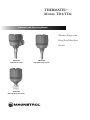
THERMATEL
®
MODEL TD1/TD2
Model TD1
with twin tip sensor
Model TD2
with low flow body sensor
Model TD2
with spherical tip sensor

These units are in compliance with:
1.The EMC directive 2014/30/EU.
2.Directive 2014/34/EU for equipment or protective system intended for
use in potentially explosive atmospheres. EC-type examination certifi-
cate number ISSeP13ATEX024X or ISSeP13ATEX025X. Standards
a
pplied EN60079-0:2012, EN60079-1:2007, EN60079-11:2012 and
EN60079-26:2007.
2
UNPACKING
Unpack the instrument carefully. Make sure all components
have been removed from the foam protection. Inspect all
components for damage. Report any concealed damage to
the carrier within 24 hours. Check the contents of the car-
ton/crates against the packing slip and report any discrep-
a
ncies to Magnetrol. Check the nameplate model number
to be sure it agrees with the packing slip and purchase
order. Check and record the serial number for future refer-
ence when ordering parts.
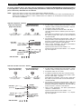
MOUNTING
Nameplate:
- partnumber amplifier - sensor
-
serial n°
- tag n°
Set up Sticker
FLOW LEVEL
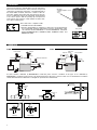
For flow switches calibrated by MAGNETROL, install the probe near the centerline of the pipe. If not calibrated by
MAGNETROL, install the probe at least 1/4 diameter depth into the pipe. For best results it is recommended to install the
switch with minimum five diameters of straight run upstream and downstream.
Direction of
flow
Direction of
flow
Direction of
level movement
4321
21
UP
DOWN
Flow / No flow
Low Flow
Body
Overflow
O
verflow
t
ank
O
verflow
t
ank
Off gas
G
as vent
Switch at set flow rate
Output line
Additive flow
o
utput line
I
nput line
I
nterface
High level
alarm
L
ow level alarm
Pump protection
Leak detection
Threaded Welded flange

P
OWER
HEATER
TEMP COMP
MEDIA
RANGE
FAILSAFE
FAU LT
O
F
F
G
A
SE
O
N
LS
I
L
L
O
N
Q
H
L
O
F
F
A
LARM
MODEL TD1
NC C NO NC C NO
3
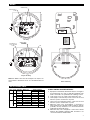
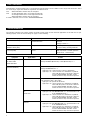
WIRING
RELAY CONNECTIONS
8A DPDT Relay
24 V DC (± 20 %)
Power
Note: For ATEX II 1G / zone 0: mA signal can only be con-
nected when a Thermatel sensor of 1 mm wall thickness is
used.
TD1 Wiring
TIME
DELAY
ALARM
MODEL TD2
NC C NO NC C NO TP2
TP1
L2L1
8
A DPDT Relay
o
r 1A H.S.
D
PDT Relay
mA
24 V DC (± 20 %)
or 100 - 264 V AC
Power
Integral TD2 Wiring
Remote TD2 Wiring
16
TB4
123456
Shield
1 - white
2 - black
3 - red
4 - green
5 - orange
6
- blue
Power
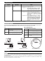
Level Fail-safe Relay coil Relay terminals
position NC to C NO to C
On High HLFS De-energized Closed Open
LLFS Energized Open Closed
Low HLFS Energized Open Closed
LLFS De-energized Closed Open
Fail High HLFS De-energized Closed Open
LLFS De-energized Closed Open
Low HLFS De-energized Closed Open
LLFS De-energized Closed Open
CHART NOTES AND DEFINITIONS:
1. Equipment controlled by Thermatel
®
relays is assumed to
be powered from one source, while the Thermatel
®
unit
itself is assumed to be powered from a different source.
2. “Fail” means a loss of power to the Thermatel
®
unit.
3. HLFS (High Level Fail-safe) means a flow rate or level
which is equal to or above the set point.
4. LLFS (Low Level Fail-safe) means a flow rate or level
which is equal to or below the set point.
5. When the relay coil is de-energized, a connection is
made between the terminals COM (common) and NC
(normally closed), and there is no connection between
COM and NO (normally open).
6. When the relay coil is energized, a connection is made
between the terminals COM and NO, and there is no
connection between COM and NC.

4
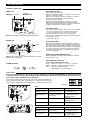
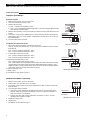
Indication and functions
Switch setup
SETUP AND FUNCTIONS
FAIL-SAFE (TD1/TD2):
HLFS (High Level Fail-safe):
Relay is energized when flow < setpoint or sensor dry (or
in the low conductive liquid).
Relay is de-energized when flow ≥ setpoint or sensor is
immerged (or in the higher conductive liquid).
LLFS (Low Level Fail-safe):
Relay is energized when flow > setpoint or sensor is
immerged (or in the higher thermal conductive liquid).
Relay is de-energized when flow ≤ setpoint or sensor dry
(or in the lower thermal conductive liquid).
mA SIGNAL (TD2):
The mA is a non linear signal of the actual process conditions;
- for flow: mA output increases as the flow rate increases
- for level: mA output increases when in a wet condition.
The mA value depends upon sensor and application.
Error reporting is determined by setting of the Fail Safe mode;
- failsafe low ≤ 3,6 mA
- failsafe high ≥ 22 mA
TESTPOINTS (TD2):
Measure and record the voltage between TP1 and TP2.
This voltage will change as the set point potentiometer is
adjusted. Voltage readings will be between 0 and 5 VDC.
This value may be used for future reference or adjustment
of set point. This value can be recorded and checked in
the future to ensure that the set point has not changed
since last calibration.
TIME DELAY POTENTIOMETER (TD2):
Before calibration, turn fully counterclockwise until click
(max. 30 turns) = 0 s.
LED INDICATION (TD1/TD2):
(in accordance with fail-safe mode)
green LED ON = safe
(one or more of the 2 green LED's)
(TD2)
yellow LED ON = reaching switch point (TD2)
Red LED ON = alarm (TD1/TD2)
LED BLINKS = error (TD1/TD2).
P
OWER
HEATER
TEMP COMP
M
EDIA
R
ANGE
FAILSAFE
F
AU LT
O
F
F
G
A
SE
O
N
LS
I
L
L
O
N
Q
H
L
O
F
F
ALARM
MODEL TD1
NC C NO NC C NO
POWER
HEATER
TEMP COMP
MEDIA
RANGE
FAILSAFE
FAU LT
O
F
F
G
A
SE
O
N
LS
I
L
L
O
N
Q
H
L
O
F
F
ALARM
MODEL TD1
NC C NO NC C NO
P
OWER LED
U
nit powered = green LED on
A
LARM LED
R
ed LED on = alarm
R
ed LED blinks = error
mA signal
Test points
Alarm potentiometer
Time delay potentiometer
L
ED indication
Turn
to go into alarm
Turn
to come out of alarm
ALARM
Potentiometer
Note: during initial power-on, red LED will blink slowly.
Note: during initial power-on, all LED’s will turn on and indi-
vidually OFF = unit ready.
ALARM (TD1/TD2)
TIME
D
ELAY
A
LARM
MODEL TD2
NC C NO NC C NO TP2
T
P1
L2L1
TIME
DELAY
ALARM
MODEL TD2
NC C NO NC C NO TP2
TP1
L2L1
MODEL TD1
MODEL TD2
The TD1/TD2 switch settings are pre-set from factory. The factory default set-
tings are marked on the sticker on the electronics. These positions may need
to be changed, depending upon the application – consult the following table.
For factory calibrated devices, the switch setup and calibration is completed by MAGNETROL for optimal performance
in your application. The dip-switch settings and/or potentiometers should only be adjusted for troubleshooting pur-
poses if the factory calibration was not sufficient.
SET 1
SET 1
SET 2
Set up sticker
SET 2
SET 1
TD1/TD2 Purpose Settings
HEATER / HTR (4) Control heat to sensor
+ for flow applictions
- for level applications
TEMP COMP / TC
(3)
De-activate temperature
compensation
OFF: use only in case
recommended by factory
ON: default setting
MEDIA (2) Gas or Liquid
G: Gases
L: Liquids, default setting for
TMH/TML sensors
RANGE (1) Sensitivity S: default setting
SET 2
TD1/TD2 Purpose Settings
FAILSAFE / FS (2) Failsafe setting
HL: High Level Fail-safe
LL: Low Level Fail-safe
FAULT / FLT (1) De-activate fault indication
OFF: use only in case
recommended by factory
ON: default setting
4321
21
UP
DOWN

5
H
igh flow / High level - Interface
CALIBRATION
NOTE: Ensure that settings on page 3 have been verified before calibrating this unit.
Adjust level, interface or flow to the desired alarm condition of the actual liquid or gas. Units are preferably field cali-
brated under operating conditions or bench calibrated if the real conditions can be simulated. Consult factory when
this cannot be established.
1. Set Time delay to minimum (turn max 30 turns counter-
clockwise or until a clicking sound is heard) - only TD2.
2. Set Failsafe switch in “High” mode.
3
. Set Alarm potentiometer until red LED is ON. Allow
some time for the switch to stabilize (check mA output -
only TD2).
Relay will be de-energized, if flow or level is higher than
the actual set point or the unit sees the most thermal
conductive media.
4. Reset Alarm potentiometer until Red LED is OFF and
both green LED’s (only TD2) light UP (turn clockwise) –
tweek the potentiometer slowly back and forth until the
desired set point is reached = Red LED ON.
5. Only for level applications: turn alarm potentiometer
counterclockwise one additional turn.
Typical response time for level is within 3 - 5 s.
Typical response time for flow is within 2 - 15 s, depend-
ing on the appliction.
1. Set Time delay to minimum (turn max 30 turns counter-
clockwise or until a clicking sound is heard) - only TD2.
2. Set Failsafe switch in “Low” mode
3. Set Alarm potentiometer until: (turn counterclockwise)
red LED is ON. Allow some time for the switch to stabi-
lize (check mA output - only TD2).
Relay will be de-energized, if flow or level is lower than
the actual set point or the unit sees the least thermal
conductive media.
4. Reset Alarm potentiometer until Red LED is OFF and
both green LED’s (only TD2) light UP (turn clockwise) –
tweek the potentiometer slowly back and forth until the
desired set point is reached = Red LED ON.
5. Only for level applications: turn alarm potentiometer
clockwise
1
/2 additional turn.
Typical response time for level is within 5 - 10 s.
Typical response time for flow is within 2 - 15 s, depend-
ing on the appliction.
Low flow / No flow / Low level - Interface
ALARM
Higher mA value
mA value:
(TD2 only)
Process
condition:
High flow / Flow
Wet sensor
Low flow / No Flow
Dry sensor
Lower mA value
Setpoint
GGY R
ALARM
Lower mA value
mA value:
(TD2 only)
Process
condition:
High flow / Flow
Wet sensor
Low flow / No Flow
Dry sensor
Higher mA value
Setpoint
GG YR
Turn
for faster response to detect a
low level (dry) condition
Low Level Adjustment
(Low Level Fail-safe)
Turn
faster response to low
flow or decrease
alarm point
Turn
faster response to
reset or increase
alarm point
Low Flow Adjustment
(Low Level Fail-safe)
Turn
for faster response to detect a
high level (wet) condition
High Level Adjustment
(High Level Fail-safe)
Turn
faster alarm or
decrease alarm point
Turn
faster reset or
increase alarm point
High Flow Adjustment
(High Level Fail-safe)
For factory calibrated devices, the switch setup and calibration is completed by MAGNETROL for optimal performance
in your application. The dip-switch settings and/or potentiometers should only be adjusted for troubleshooting pur-
poses if the factory calibration was not sufficient.
LED indication:
LED indication:

6
F
AULT INDICATION
TROUBLESHOOTING
T
D1/TD2 have continuous diagnostics to ensure that the signal from the sensor is within a select range. If the electronics detect
an “out of range” signal, the switch has registered an instrument error.
TD1: Alarm LED blinks and the relay de-energizes.
TD2: 3,6 mA signal when unit is set for low level fail-safe.
22 mA signal when unit is set for high level fail-safe.
Alarm LED blinks and the relay de-energizes.
If a fault is detected, refer to section “TROUBLESHOOTING”.
The TD1/TD2 switches have various settings to handle a wide variety of flow and level applications. If the switch is not per-
forming properly, check the switch settings on page 4 or the following:
Symptom Problem Solution / Action
Red LED does not go ON Switch point cannot be established for
air flow detection
Check whether probe is extended into
the flow.
Change Heater to “-”
Green LED OFF (TD1)
All LED’s OFF (TD2)
No power 1. Check power supply
2. Check wiring at wiring terminals
Red LED blinks and ≤ 3,6 mA or
≥ 22 mA (TD2)
An instrument error has been regis-
tered
By changing the switch settings, the
unit may return to normal operation
mode. If not, consult factory.
Symptom Application Action*
Unable to adjust set point
to obtain alarm
Fault LED blinks
Air Flow Detection Ensure that the probe is extended into the flow
Change HEATER (Model TD1) / HTR (Model TD2) to “–”
Switch indicates a fault
(red LED will blink)
Liquid Level – Sensor Wet Verify HEATER (TD1) / HTR (TD2) is set to “–”
Change HEATER/HTR to “+”
Light goes off—contact factory to discuss application.
Light stays on—check resistance to determine if a problem
exists with the probe or electronics. Refer to
Section “RESISTANCE VALUES”. Probe
and/or electronics may need to be replaced.
Liquid Level – Sensor Dry Verify HEATER (TD1) / HTR (TD2) is set to “–”
Turn off FAULT (TD1) / FLT (TD2)
Light goes off—operate in this mode
Light stays on—check resistance to determine if a problem
exists with the probe or electronics. Refer to
Section “RESISTANCE VALUES”. Probe
and/or electronics may need to be replaced.
Liquid Flow – Sensor Dry
or
No Air Flow
Turn off FAULT (TD1) / FLT (TD2)
Light goes off—run HEATER/HTR at “+” and FAULT/FLT “off”
or run HEATER/HTR at “-”
Light stays on—check resistance to determine if a problem
exists with the probe or electronics. Refer to
Section “RESISTANCE VALUES”. Probe
and/or electronics may need to be replaced.
Liquid Flow – Sensor Wet
No Flow
Switch HEATER/HTR to “-”
Light goes off—run HEATER/HTR at “+” and FAULT/FLT “off”
or run HEATER/HTR at “-”
Light stays on—check resistance to determine if a problem
exists with the probe or electronics. Refer to
Section “RESISTANCE VALUES”. Probe
and/or electronics may need to be replaced.

7
T
ROUBLESHOOTING
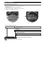
RESISTANCE VALUES
The following tables provide the expected resistance values for the sensor. Refer to the indicated figures for pin locations.
Refer to section “REPLACEMENT PARTS / Probe replacement” for removing bezel and circuit boards.
The probe may be cleaned by soaking, spraying solvents or detergent and water onto the sensor tubes, or by ultrasonic clean-
ing. Lime deposits may be safely removed by soaking in 20 % hydrochloric acid. Warming to +65 °C (+150 °F) is permissible
to speed this process.
For unusual cleaning problems, contact the factory and determine the exact materials of construction and chemical compat-
ibility before using strong acids or unusual cleansers.
Pin Expected Resistance
1 to 3
90 to 180 ohms
(275 ohms with high temperature probe)
2 to 4
90 to 180 ohms
(275 ohms with high temperature probe)
TD1
Pin Expected Resistance
1 to 3 or 4
90 to 180 ohms
(90 to 275 ohms with high temperature probe)
2 to 5 or 6
90 to 180 ohms
(90 to 275 ohms with high temperature probe)
1 to 2, 3 to 4,
5 to 6
0 to 12 ohms
TD2 – Integral Electronics
TD2 – Remote Electronic Enclosure
14
14
16
16
123456
Shield
Unmarked Wires
Marked Wires
Unmarked Wires
Marked Wires
TD1 Probe Connections
TD2 Integral Probe Connections
TD2 Remote Probe Connections
Cleaning
MAINTENANCE
Symptom Application Action*
Switch indicates a fault
(red LED will blink)
Liquid Flow – Flow
Present
Turn off TEMP COMP (TD1) / TC (TD2)
Light goes off—operate in this mode
Light stays on—check resistance to determine if a problem
exists with the probe or electronics. Refer to
Section “RESISTANCE VALUES”. Probe
and/or electronics may need to be replaced.
Air Flow – Flow Present Switch HEATER/HTR to “-”
Light goes off—Operate at lower heater power (with less
sensitivity). Turn TEMP COMP/TC off if problem
continues (requires re-calibration) or operate at
HEATER/HTR “+” and make sure FAULT/FLT
switch is “off”
Light stays on—Return HEATER/HTR switch to "+" and turn
TEMP COMP/TC "off". If light goes off then
recalibrate and operate in this mode. If light
stays on check resistance to determine if a
problem exists with the probe or electronics.
Refer to Section “RESISTANCE VALUES”.
Probe and/or electronics may need to be
replaced.
* C
hanging HEATER/HTR, TEMP COMP/TC or media switch position requires recalibration.

8
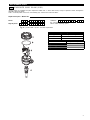
REPLACEMENT PARTS
P
robe replacement
Note: The switch will require recalibration (see page 5) following probe or electronics replacement.
INTEGRAL ELECTRONICS
Removal of probe
1. Make sure the power source is turned off.
2
. Unscrew and remove housing cover.
3. Remove the bezel by:
a. TD1 – removing the fastening screws.
b. TD2 – put a screwdriver blade through hole in center and gently pull the handle
away from the terminal strips.
4. Remove the fastening screws for the bracket. Remove bracket and attached circuit
b
oards.
5. Loosen the screws on the terminal block to remove the four leads from the probe.
Note that the TD1 uses a four position terminal block and the TD2 uses a six posi-
tion terminal block.
6. Unscrew probe from enclosure.
Installation of replacement probe
1. The probe’s leads have been separated at the factory.
One set of leads is marked with a “1,” the second set is unmarked. Connect leads
from RTD #1:
TD1 – Connect between terminals 1 and 3.
TD2 – Connect between terminals 2 and 5.
2. Connect the second set of leads:
TD1 – Connect between terminals 2 and 4.
TD2 – Connect between terminals 1 and 4.
3. Replace bezel and housing cover.
TD1 – Replace bezel and refasten screws.
TD2 – Reinstall bracket assembly. Ensure that the tab at the bottom of the bracket
engages in the hole in the bottom of housing. Reinstall bracket mounting screws.
Replace bezel by gently pressing down on the center of the bezel. Ensure that the
outer edge of bezel is evenly seated in the housing.
4. Replace housing cover.
5. Apply power.
6. Recalibrate as described on page 5.
REMOTE ELECTRONICS (TD2 ONLY)
1. Make sure the power source is turned off.
2. Remove the cover from the sensor enclosure.
3. Loosen the screws on the four position terminal block (TB1) to remove the leads
from the probe.
4. Unscrew probe from enclosure.
a. The probe’s leads have been separated at the factory. Connect leads from
RTD #1, which are grouped and marked, to pins 3 & 4 (the two terminals on
TB1 closest to the sensor label).
b. Connect the other pair of leads, which are not marked, to pins 1 & 2 (the
remaining two positions on TB1).
5. Replace housing cover.
6. Apply power.
7. Recalibrate as described on page 5.
14
14
16
16
Unmarked Wires
M
arked Wires
Unmarked Wires
Marked Wires
TD1 Probe Connections
TD2 Integral Probe Connections
41
TB1
Unmarked Wires
Marked Wires
TD2 Remote Probe Connections

9
REPLACEMENT PARTS
1
3
2
4
Replacement parts – Model TD1
1X
74
2 3 8 9 105
6
Digit in partn°:
T D 1
Partn°:
Serial n°:
X = product with a specific customer requirement
See nameplate, always provide complete partn° and
serial n° when ordering spares.
(1) Housing cover
Digit 10 Replacement part
0 or 1 004-9225-002
2 or 3 004-9225-003
Replacement part
(2) Electronic module 089-7250-001
(3) "O"-ring 012-2201-237
(4) Sensor consult factory
E X P E D I T E S H I P P L A N ( E S P )
S
everal parts are available for quick shipment, within max. 1 week after factory receipt of purchase order, through the
Expedite Ship Plan (ESP).
Parts covered by ESP service are conveniently grey coded in the selection tables.

10
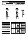
REPLACEMENT PARTS
Replacement parts – Model TD2
1X
74
2 3 8 9 105
6
D
igit in partn°:
T D 2
Partn°:
X = product with a specific customer requirement
See nameplate, always provide complete partn° and
serial n° when ordering spares.
1
2
3
}
4
1
2
3
}
5
3
4
I
NTEGRAL ELECTRONICS REMOTE ELECTRONICS
(1) Housing cover
Digit 7 Digit 10 Replacement part
0
0 or 1 004-9192-009
2 or 3 004-9224-014
1
0 or 1 036-4410-010
2 or 3 not applicable
(5) Housing cover
Digit 8 Digit 10 Replacement part
1
0 or 1 004-9225-002
2 or 3 004-9225-003
(3) "O"-ring
Digit 10 Replacement part
0, 1, 2 or 3 012-2201-237
(2) Electronic module
Digit 4 Digit 5 Digit 8 Digit 9 Digit 10 Replacement part
7
D
0
3 or G
0, 1, 2 or
3
089-7250-002
C 089-7250-010
1
3 or G
0, 1, 2 or
3
089-7250-004
C 089-7250-012
H
0
3 or G
0, 1, 2 or
3
089-7250-006
C
1
3 or G
0, 1, 2 or
3
089-7250-008
C
8
D
0
3 or G
0, 1, 2 or
3
089-7250-003
C 089-7250-011
1
3 or G
0, 1, 2 or
3
089-7250-005
C 089-7250-013
H
0
3 or G
0, 1, 2 or
3
089-7250-007
C
1
3 or G
0, 1, 2 or
3
089-7250-009
C
Replacement part
(4) Sensor consult factory
Serial n°:

11
MODEL IDENTIFICATION
T
D1
T
D2
A complete measuring system consists of:
1. THERMATEL
®
electronics
2. Connecting cable (only applicable for remote mount TD2 units)
3. THERMATEL
®
sensor
4. Optional: Order code for thread-on mounting flanges
5. Optional: Retractable probe assembly, consult factory for details
6. Optional: Factory calibration, consult factory
1. Code for Thermatel
®
TD1 electronics
APPROVAL
T
0
D 0
2
D 1 0
complete code for Thermatel
®
TD1 electronics
TD1-2 D0 0-0 Integral mount electronics for 24 V DC power supply and with 1 DPDT
8 A DPDT output relay
3 Weatherproof
C ATEX/IEC flameproof enclosure with intrinsically safe probe circuitry
HOUSING / CABLE ENTRY
0 IP66, Cast aluminium, 3/4" NPT cable entry (2 entries - 1 plugged)
1 IP66, Cast aluminium, M20 x 1,5 cable entry (2 entries - 1 plugged)
X = product with a specific customer requirement

12
1. Code for Thermatel
®
TD2 electronics with housing for industrial use
OUTPUT
ACCESSORIES
0 Blind housing cover
1 Housing cover with glass window (for aluminium housings only)
MOUNTING CONFIGURATION
0 Integral electronics
1 Remote electronics
APPROVAL
¿
3 Weatherproof
C Zone 0 – for level applications
ATEX/IEC flameproof enclosure with intrinsically safe probe circuitry
- no mA output available
- only available with 8 A DPDT relay option
G Zone 1 – for level and flow applications
ATEX/IEC flameproof enclosure
D0 8 A DPDT relay
H
0 1 A Hermetically sealed DPDT relay (Relay contact material: gold plated)
POWER SUPPLY
7 240 V AC (100-264 V AC)
8 24 V DC (± 20 %)
HOUSING / CABLE ENTRY
T 0D 2
complete code for Thermatel
®
TD2 electronics with housing for industrial use
T
D2 Electronics with continuous LED indication and mA output
0 IP66, Cast aluminium, 3/4" NPT cable entry (2 entries - 1 plugged)
1 IP66, Cast aluminium, M20 x 1,5 cable entry (2 entries - 1 plugged)
2 IP66, Cast stainless steel, 3/4" NPT cable entry (2 entries - 1 plugged)
3 IP66, Cast stainless steel, M20 x 1,5 cable entry (2 entries - 1 plugged)
¿
Consult factory for zone 0 applications in combination with hermetically sealed relay.
X = product with a specific customer requirement
MODEL IDENTIFICATION
2. Code for connecting cable used with weatherproof remote mount TD2 electronics (6-wire cable/shielded). Consult
factory for cable suitable for flameproof enclosure.
0
8
1 9
3
3 7
complete code for connecting cable
003- 150
From 3 m (10 ft) min. to 150 m (500 ft) max. Specify in increments of 1 m (3.28 ft)

13
C
ONNECTIONS
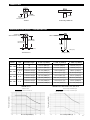
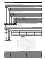
DIMENSIONS IN mm (inches) – TMA/TMB/TMC/TMD
PRESSURE/TEMPERATURE RATING – TMA/TMB/TMC/TMD
T
hreaded Welded flange ASME - EN
Insertion
length
BSP connection
Insertion
length
Insertion
length
NPT connection
Threaded Sensor
F
langed Sensor
Insertion length
N
PT connection
Insertion length
B
SP connection
I
nsertion
l
ength
Standard: 46 (1.81)
With heat extension: 223 (8.78)
S
tandard: 60 (2.36)
W
ith heat extension: 223 (8.78)
ø 22,9 (0.90)
ø 22,9 (0.90)
TMA/TMB sensors
TMC/TMD sensors with material code A, D, K, M or N
Insertion length = minimum length
In
se
rtio
n
le
n
g
th
>
min
imu
m
le
n
g
th
Sensor
Material
code
Insertion length
Maximum process pressure
@ +40 °C (+100 °F) @ +120 °C (+250 °F) @ +200 °C (+400 °F)
TMA, TMB
A All 41,4 bar (600 psi) 33,8 bar (490 psi) 28,6 bar (415 psi)
K, M, N All 27,6 bar (400 psi) 22,4 bar (325 psi) 19,0 bar (275 psi)
TMC, TMD
A, D, K,
M, N
= minimum length 207 bar (3000 psi) 170 bar (2460 psi) 148 bar (2140 psi)
> minimum length 128 bar (1850 psi) 105 bar (1517 psi) 91,0 bar (1320 psi)
TMC, TMD B, F
= minimum length 207 bar (3000 psi) 181 bar (2627 psi) 161 bar (2340 psi)
> minimum length 103 bar (1500 psi) 90,6 bar (1313 psi) 80,7 bar (1170 psi)
TMC, TMD C, G
= minimum length 172 bar (2500 psi) 147 bar (2125 psi) 137 bar (1980 psi)
> minimum length 82,8 bar (1200 psi) 70,3 bar (1020 psi) 65,5 bar (950 psi)
Process temperature (°C)
Process pressure (bar)
Process temperature (°C)
Process pressure (bar)
Material code A
Ma
teria
l c
o
de
K, M o
r
N

14
MODEL IDENTIFICATION
3. Order code for Thermatel
®
TD1/TD2 – STANDARD SENSOR
P
RO
CE
S
S
CO
NNE
CT
IO
N
–
S
IZ
E
/T
Y
P
E
T
h
r
e
a
d
e
d
complete order code for Thermatel
®
TD1/TD2 STANDARD SENSOR
T 0M
INSERTION LENGTH – MINIMUM
INSERTION LENGTH – SELECTABLE – Specify per cm (0.39") increment
1 1
0
3
/4
"
N
P
T
2 1
0
1
"
N
P
T
2 2
0
1
"
B
S
P
(
G
1
")
ASME flanges
MATERIAL OF CONSTRUCTION FOR SENSOR AND PROCESS CONNECTION
TMA Spherical tip - standard max +120 °C (+250 °F)
¿
TMB Spherical tip - with heat extension max +200 °C (+400 °F)
TMC Twin tip - standard max +120 °C (+250 °F)
¿
TMD Twin tip - with heat extension max +200 °C (+400 °F)
¿
T
MA/TMC sensors can handle process temperatures up to +200 °C (+400 °F) with remote electronics.
¿
Not suitable for zone 0 applications in combination with hermetically sealed relay; use in this case material code D.
X = product with a specific customer requirement
Sensor Process connection
0 0 5
5 cm (2")
TMA, TMB
NPT
0 0 6
5,5 cm (2.17") flanged
0 0 7
7 cm (2.76") BSP
0 0 6
5,5 cm (2.17")
TMC, TMD
NPT, flanged
0 0 8
7,5 cm (3") BSP
Sensor Process connection
0 0 6
Minimum 6 cm (2.36")
TMA, TMB
NPT
0 0 7
Minimum 7 cm (2.76") flanged
0 0 8
Minimum 8 cm (3.15") BSP
0 0 7
Minimum 7 cm (2.76")
TMC, TMD
NPT, flanged
0 0 9
Minimum 9 cm (3.54") BSP
3 3 0
Maximum 330 cm (130") all all
A
316/316L (1.4401/1.4404) stainless steel
➀
B Hastelloy
®
C (2.4819) – TMC/TMD only
C Monel
®
(2.4360) – TMC/TMD only
D 316/316L (1.4401/1.4404) stainless steel – TMC/TMD only
F Hastelloy
®
C (2.4819), NACE
G Monel
®
(2.4360), NACE
K 316/316L (1.4401/1.4404) stainless steel, ASME B31.3
M 316/316L (1.4401/1.4404) stainless steel, ASME B31.3 and NACE
N 316/316L (1.4401/1.4404) stainless steel, NACE
350 1 1/2" 600 lbs ASME RF
430 2" 150 lbs ASME RF
440 2" 300 lbs ASME RF
450 2" 600 lbs ASME RF
2 3 0 1" 150 lbs ASME RF
240 1" 300 lbs ASME RF
250 1" 600 lbs ASME RF
330 1 1/2" 150 lbs ASME RF
340 1 1/2" 300 lbs ASME RF
BB0 DN 25 PN 16/25/40 EN 1092-1 Type A
BC0 DN 25 PN 63/100 EN 1092-1 Type B2
CB0 DN 40 PN 16/25/40 EN 1092-1 Type A
CC0 DN 40 PN 63/100 EN 1092-1 Type B2
DA0 DN 50 PN 16 EN 1092-1 Type A
DB0 DN 50 PN 25/40 EN 1092-1 Type A
DD0 DN 50 PN 63 EN 1092-1 Type B2
DE0 DN 50 PN 100 EN 1092-1 Type B2
EN flanges
No threads
–
only for use with compression fitting
000 Compression fitting (customer-supplied)

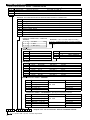
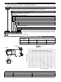
DIMENSIONS IN mm (inches) – TMH
Maximum process pressure
@ +40 °C (+100 °F) @ +120 °C (+250 °F) @ +200 °C (+400 °F) @ +450 °C (+850 °F)
414 bar (6000 psi) 339 bar (4920 psi) 295 bar (4280 psi) 233 bar (3380 psi)
Process temperature (°C)
Process pressure (bar)
PRESSURE/TEMPERATURE RATING – TMH
251
(9.88)
Insertion
length
BSP
connection
Insertion
length
NPT
connection
Insertion length
Flanged
connection
273
(10.75)
254
(10.00)
Ø
21,9
(
0.86)
Ø 21,9
(0.86)
15

16
MODEL IDENTIFICATION
3. Order code for Thermatel
®
TD1/TD2 – HIGH TEMPERATURE / HIGH PRESSURE SENSOR
complete order code for Thermatel
®
TD1/TD2
HIGH TEMPERATURE /HIGH PRESSURE SENSOR
T
0
M H
TMH High temperature / high pressure twin tip – max +450 °C (+850 °F) / max 414 bar (6000 psi)
¿
PROCESS CONNECTION – SIZE/TYPE
Threaded
110 3/4" NPT
2
10 1" NPT
220 1" BSP (G 1")
EN flanges
BB0 DN 25 PN 16/25/40 EN 1092-1 Type A
BC0 DN 25 PN 63/100 EN 1092-1 Type B2
BG0 DN 25 PN 250 EN 1092-1 Type B2
CB0 DN 40 PN 16/25/40 EN 1092-1 Type A
CC0 DN 40 PN 63/100 EN 1092-1 Type B2
CG0 DN 40 PN 250 EN 1092-1 Type B2
CJ0 DN 40 PN 400 EN 1092-1 Type B2
DA0 DN 50 PN 16 EN 1092-1 Type A
DB0 DN 50 PN 25/40 EN 1092-1 Type A
DD0 DN 50 PN 63 EN 1092-1 Type B2
DE0 DN 50 PN 100 EN 1092-1 Type B2
DG0 DN 50 PN 250 EN 1092-1 Type B2
DJ0 DN 50 PN 400 EN 1092-1 Type B2
¿
N
ot available with retractable probe assembly.
¿
Not suitable for zone 0 applications in combination with hermetically sealed relay; use in this case material code D.
X = product with a specific customer requirement
INSERTION LENGTH – MINIMUM
Process connection
0 0 6 5,5 cm (2.17") NPT
0 0 7 7 cm (2.76") flanged
0 0 8 7,5 cm (3") BSP
Process connection
0 0 7 Minimum 7 cm (2.76") NPT
0 0 8 Minimum 8 cm (3.15") flanged
0 0 9 Minimum 9 cm (3.54") BSP
0 9 1 Maximum 91 cm (36") all
INSERTION LENGTH – SELECTABLE – Specify per cm (0.39") increment
A 316/316L (1.4401/1.4404) stainless steel
➀
B Hastelloy
®
C (2.4819)
D 316/316L (1.4401/1.4404) stainless steel
F Hastelloy
®
C (2.4819), NACE
K 316/316L (1.4401/1.4404) stainless steel, ASME B31.3 (CRN Available)
M
316/316L (1.4401/1.4404) stainless steel, ASME B31.3 and NACE (CRN Available)
N 316/316L (1.4401/1.4404) stainless steel, NACE
MATERIAL OF CONSTRUCTION FOR SENSOR AND PROCESS CONNECTION
230 1" 150 lbs ASME RF
240 1" 300 lbs ASME RF
250 1" 600 lbs ASME RF
270 1" 900/1500 lbs ASME RF
330 1 1/2" 150 lbs ASME RF
340 1 1/2" 300 lbs ASME RF
350 1 1/2" 600 lbs ASME RF
370 1 1/2" 900/1500 lbs ASME RF
380 1 1/2" 2500 lbs ASME RF
430 2" 150 lbs ASME RF
440 2" 300 lbs ASME RF
450 2" 600 lbs ASME RF
470 2" 900/1500 lbs ASME RF
480 2" 2500 lbs ASME RF
ASME flanges

17
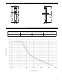
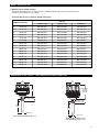
46
(1.81)
Insertion
length
ø 16
(0.63)
Pipe size Water Air
1/2" 0,75 to 680 l/h (0.2 to 180 GPH) 0,85 to 120 Nm
3
/h (0.5 to 70 SCFM)
3/4" 2 to 900 l/h (0.5 to 240 GPH) 2,5 to 170 Nm
3
/h (1.5 to 100 SCFM)
1" 3,8 to 1600 l/h (1 to 420 GPH) 5 to 290 Nm
3
/h (3 to 170 SCFM)
Insertion length
Maximum process pressure
@ +40 °C (+100 °F) @ +120 °C (+250 °F) @ +200 °C (+400 °F)
= 2,5 cm (1") 207 bar (3000 psi) 170 bar (2460 psi) 148 bar (2140 psi)
> 2,5 cm (1") 128 bar (1850 psi) 105 bar (1517 psi) 91,0 bar (1320 psi)
MODEL IDENTIFICATION
DIMENSIONS IN mm (inches) & PRESSURE/TEMPERATURE RATING – TMM
RECOMMENDED FLOW RANGES – TMM
Insertion length = minimum length
Insertion length > minimum length
Process temperature (°C)
Process pressure (bar)
T
0
1M M
complete order code for Thermatel
®
TD1/TD2 MINI SENSOR
3. Order code for Thermatel
®
TD1/TD2 – MINI SENSOR
T
MM Mini twin tip – max +120 °C (+250 °F)
¿
PROCESS CONNECTION – SIZE/TYPE
Threaded
010 1/2" NPT
110 3/4" NPT
210 1" NPT
INSERTION LENGTH – MINIMUM
003 2,5 cm (1")
INSERTION LENGTH – SELECTABLE – Specify per cm (0.39") increment
005 Minimum 5 cm (2")
330 Maximum 330 cm (130")
¿
TMM sensors can handle process temperatures up to +200 °C (+400 °F) with remote electronics.
X = product with a specific customer requirement
¿
Not suitable for zone 0 applications in combination with hermetically sealed relay.
A 316/316L (1.4401/1.4404) stainless steel (CRN Available)
¿
N 316/316L (1.4401/1.4404) stainless steel, NACE (CRN Available)
MATERIAL OF CONSTRUCTION FOR SENSOR AND PROCESS CONNECTION

18
M
ODEL IDENTIFICATION
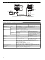
DIMENSIONS IN mm (inches) & PRESSURE/TEMPERATURE RATING – TML
RECOMMENDED FLOW RANGES – TML
¿
TML sensors can handle process temperatures up to +200 °C (+400 °F) with remote electronics.
T
A
M L 0 0
complete order code for Thermatel
®
TD1/TD2 LOW FLOW BODY SENSOR
3
. Order code for Thermatel
®
T
D1/TD2 – LOW FLOW BODY SENSOR
TML Low flow body – max +120 °C (+250 °F)
¿
/ max 400 bar (5800 psi)
MATERIAL OF CONSTRUCTION FOR SENSOR AND PROCESS CONNECTION
A 316/316L (1.4401/1.4404) stainless steel
¿
MOUNTING BRACKET
0 0 0 None
100 With carbon steel mounting bracket
PROCESS CONNECTION – SIZE/TYPE
Threaded
T1 1/4" NPT-F (CRN Available)
V1 1/2" NPT-F (CRN Available)
T0 1/4" BSP (G 1/4")
V0 1/2" BSP (G 1/2")
X = product with a specific customer requirement
2 holes
ø 9,5 (0.37)
51
(2.00)
70
(2.75)
89
(3.50)
76
(3.00)
95
(3.75)
32
(1.25)
optional mounting
bracket
51 (2.0)
1
/4" or
1
/2"
NPT or BSP
Size Water Air
1/4" flow body 0,02 to 5,7 l/h (0.0055 to 1.5 GPH)
0,071 to 5,75 Nm
3
/h (2.5 to 200 SCFH)
¿
1/2" flow body 0,04 to 11,5 l/h (0.01 to 3 GPH) 0,071 to 11,5 Nm
3
/h (2.5 to 400 SCFH)
Process temperature (°C)
Process pressure (bar)
¿
N
ot suitable for zone 0 applications in combination with hermetically sealed relay.
0 Standard
1 High Sensitivity
¿
SENSITIVITY
¿
O
nly available for gas applications and when digit 5 = T.
Sensitivity (refer
to digit 7)
Maximum process pressure
@ +40 °C (+100 °F) @ +120 °C (+250 °F) @ +200 °C (+400 °F)
Standard sensitivity 517 bar (7500 psi) 517 bar (7500 psi) 500 bar (7250 psi)
High sensitivity
400bar (5800psi) 328bar (4760 psi) 283bar (4100 psi)
Standard sensitivity
High sensitivity
¿
For 0,0078 to 0,0708 Nl
3
/h (0.064 to 2.5 SCFH) use high sensitivity low flow body sensor.

19
MODEL IDENTIFICATION
4. Optional sensor mounting flanges
Thread-on mounting flanges can only be used in combination with 3/4" NPT process connection sensor.
Consult factory for other sizes or materials.
Thread-on flanges for use with 3/4" NPT-M connections
ASME B16.5 flanges
Part No.
Carbon steel 316/316L SST Hastelloy C
1" 150 lbs RF 004-5867-041 004-5867-043 004-5867-052
1 1/2" 150 lbs RF 004-5867-021 004-5867-001 004-5867-031
2" 150 lbs RF 004-5867-022 004-5867-002 004-5867-032
3
" 150 lbs RF 004-5867-023 004-5867-003
0
04-5867-033
4" 150 lbs RF 004-5867-024 004-5867-004 004-5867-034
6" 150 lbs RF 004-5867-025 004-5867-005 004-5867-035
1" 300 lbs RF 004-5867-042 004-5867-044 004-5867-053
1 1/2" 300 lbs RF 004-5867-026 004-5867-006 004-5867-036
2" 300 lbs RF 004-5867-027 004-5867-007 004-5867-037
3" 300 lbs RF 004-5867-028 004-5867-008 004-5867-038
4" 300 lbs RF 004-5867-029 004-5867-009 004-5867-039
6" 300 lbs RF 004-5867-030 004-5867-010 004-5867-040
1" 600 lbs RF 004-5867-051 004-5867-050 004-5867-054
1 1/2" 600 lbs RF 004-5867-046 004-5867-045 004-5867-055
2" 600 lbs RF 004-5867-049 004-5867-048 004-5867-056
DIMENSIONS IN mm (inches) – WITH HOUSING FOR INDUSTRIAL USE
102
(4.00)
100
(3.95)
Insertion
length
Threaded: 46 (1.81)
Welded flange: 60 (2.36)
Heat extension: 223 (8.78)
Ø 22,9 (0.90)
Model TD1 with TMC/TMD twin tip sensor
102
(4.00)
without window
113 (4.43)
with window
123 (4.85)
Insertion
length
Threaded: 46 (1.81)
Welded flange: 60 (2.36)
Heat extension: 223 (8.78)
Ø 22,9 (0.90)
Model TD2 with integral electronics
and TMA/TMB spherical tip sensor

20
DIMENSIONS IN mm (inches) – WITH HOUSING FOR INDUSTRIAL USE
100
(3.95)
1
02
(
4.00)
7
0
(
2.75)
2 holes
Ø 9,5
(0.37)
89
(3.50)
95
(3.75)
1
9
(
0.37)
60 (2.36)
Model TD2 with remote electronics
102
(4.00)
1
02
(
4.00)
without window
113 (4.43)
with window
123 (4.85)
Insertion
length
m
ax 150 m (500 ft)
c
able is ordered separately
Ø
22,9 (0.90)
Remote TMA spherical tip sensor
with flanged connection
SPECIFICATIONS
Electronics specifications – with housing for industrial use
Description TD1 TD2
Power supply 19,2 to 28,8 V DC 19,2 to 28,8 V DC
100 to 264 V AC, 50-60 Hz
Power consumption 3,5 W @ 24 V DC 4 W @ 24 V DC or 5 W @ 264 V AC
Flow range
Water
0,01 to 5,0 FPS (0,003 to 1,5 m/s)(spherical tip and twin tip sensors)
0,01 to 1,0 FPS (0,003 to 0,3 m/s)(HTHP, Hastelloy, Monel sensors)
Air
0,01 to 500 SFPS (0,03 to 150 Nm/s)
Output Alarm DPDT relay: 8 A @ 120 V AC / 250 V AC
8 A @ 30 V DC; 0,5 A @ 125 V DC
Hermetically sealed relay not available Hermetically sealed DPDT relay:
1A @ 28 V DC; 0,2 A @ 125 V DC
Continuous Not applicable non linear mA for trending (not for all models
- see electronics part number on page 7)
Error Via alarm relay 3,6 mA (Low Level Fail-safe) – 22 mA (High
Level Fail-safe) and alarm relay
Time delay Not available 0 to 100 s adjustable (in addition to sensor
response time)
User interface - Local switches for gain setting, function setting and High/Low Level Fail-safe
- Calibration and time delay via potentiometer
Display LED’s for Power/Alarm status 2 green LED’s (safe condition),
1 yellow LED
(alarm setpoint being approached)
1 red LED (alarm condition)
Approvals ATEX II 2 G Ex d IIC T5..T4 Gb, flameproof enclosure - TD2 for zone 1
ATEX II 1/2 G Ex d+ib, d [ib] IIC T5..T4 Ga/Gb, flameproof enclosure - TD1 & TD2
(TD2 only with 8A DPDT relay)
IEC Ex d + ib, d [ib] IIC T5/T4 Gb/Ga - TD1 & TD2
IEC Ex d IIC T5/T4 Gb - TD2 only
Other approvals are available, consult factory for more details
SIL (Safety Integrity Level) Functional safety to SIL1 as 1oo1 / SIL2 as 1oo2 in accordance to IEC 61508 – SFF of
69,3 % (TD1) and 73 % (TD2) – full FMEDA reports and declaration sheets available
Housing material IP66/Aluminium A356T6 (<0.20 % copper) or stainless steel
Net weight Aluminium: 1,1 kg (2.4 lbs) - integral electronics only
Stainless steel: 2,6 kg (5.7 lbs) - integral electronics only
La page est en cours de chargement...
La page est en cours de chargement...
La page est en cours de chargement...
La page est en cours de chargement...
-
 1
1
-
 2
2
-
 3
3
-
 4
4
-
 5
5
-
 6
6
-
 7
7
-
 8
8
-
 9
9
-
 10
10
-
 11
11
-
 12
12
-
 13
13
-
 14
14
-
 15
15
-
 16
16
-
 17
17
-
 18
18
-
 19
19
-
 20
20
-
 21
21
-
 22
22
-
 23
23
-
 24
24


Magnetrol Thermatel TD1/TD2 Mode d'emploi
- Taper
- Mode d'emploi
dans d''autres langues
Documents connexes
-
Magnetrol Thermatel TG1/TG2 Mode d'emploi
-
-
-
-
-
Autres documents
-
 Thermal Dynamics Plasma Cutting System PAK 10 Manuel utilisateur
-
Triax TMB 2500 Manuel utilisateur
-
ESAB ESP / EPP Plumbing Box and Remote Pendant Manuel utilisateur
-
Toshiba MMU-AP0071YH Manuel utilisateur
-
Pentax MMK-AP0121H Manuel utilisateur
-
ESAB EPP-400 Plasma Power Source Manuel utilisateur
-
Miller JA399912 Le manuel du propriétaire
-
-
Toshiba MMD-AP0181SPH Le manuel du propriétaire
-
