Miller BWC-3 Le manuel du propriétaire
- Catégorie
- Système de soudage
- Taper
- Le manuel du propriétaire
Ce manuel convient également à

BWC−3
Processes
Description
TIG (GTAW) Welding
File: TIG (GTAW)
MIG (GMAW) Welding
OM-6608 199 859F
2013−03

TABLE OF CONTENTS
SECTION 1 − SAFETY PRECAUTIONS - READ BEFORE USING 1.................................
1-1. Symbol Usage 1.......................................................................
1-2. Cooling Equipment Hazards 1............................................................
1-3. Additional Symbols For Installation, Operation, And Maintenance 1.............................
1-4. California Proposition 65 Warnings 2......................................................
1-5. Principal Safety Standards 2.............................................................
1-6. EMF Information 2.....................................................................
SECTION 2 − CONSIGNES DE SÉCURITÉ − LIRE AVANT UTILISATION 3...........................
2-1. Symboles utilisés 3.....................................................................
2-2. Dangers liés aux équipements de refroidissement 3.........................................
2-3. Dangers supplémentaires en relation avec l’installation, le fonctionnement et la maintenance 3.....
2-4. Proposition californienne 65 Avertissements 4..............................................
2-5. Principales normes de sécurité 4.........................................................
2-6. Informations relatives aux CEM 4.........................................................
SECTION 3 − DEFINITIONS 5..................................................................
3-1. Additional Safety Symbols And Definitions 5................................................
3-2. Miscellaneous Symbols And Definitions 5..................................................
SECTION 4 − SPECIFICATIONS 6..............................................................
4-1. Serial Number And Rating Label Location 6................................................
4-2. Specifications 6........................................................................
SECTION 5 − INSTALLATION 7................................................................
5-1. GTAW Connections 7...................................................................
5-2. GMAW Connections 8..................................................................
SECTION 6 − MAINTENANCE & TROUBLESHOOTING 9.........................................
6-1. Routine Maintenance 9.................................................................
6-2. Coolant Maintenance 9.................................................................
6-3. Troubleshooting 10......................................................................
SECTION 7 − ELECTRICAL DIAGRAM 10........................................................
7-1. Circuit Diagram For 115 Volt Cooler 10.....................................................
7-2. Circuit Diagram For 230 Volt Cooler 10.....................................................
SECTION 8 − PARTS LIST 11...................................................................

OM-6608 Page 1
SECTION 1 − SAFETY PRECAUTIONS - READ BEFORE USING
coolers 2011−10
7
Protect yourself and others from injury — read, follow, and save these important safety precautions and operating instructions.
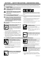
1-1. Symbol Usage
DANGER! − Indicates a hazardous situation which, if
not avoided, will result in death or serious injury. The
possible hazards are shown in the adjoining symbols
or explained in the text.
Indicates a hazardous situation which, if not avoided,
could result in death or serious injury. The possible
hazards are shown in the adjoining symbols or ex-
plained in the text.
NOTICE − Indicates statements not related to personal injury.
. Indicates special instructions.
This group of symbols means Warning! Watch Out! ELECTRIC
SHOCK, MOVING PARTS, and HOT PARTS hazards. Consult sym-
bols and related instructions below for necessary actions to avoid the
hazards.
1-2. Cooling Equipment Hazards
The symbols shown below are used throughout this manual
to call attention to and identify possible hazards. When you
see the symbol, watch out, and follow the related instructions
to avoid the hazard. The safety information given below is
only a summary of the more complete safety information
found in the Safety Standards listed in Section 1-5. Read and
follow all Safety Standards.
Only qualified persons should install, operate, maintain, and
repair this unit.
During operation, keep everybody, especially children, away.
ELECTRIC SHOCK can kill.
Touching live electrical parts can cause fatal shock
s
or severe burns. The input power circuit and machine
internal circuits are also live when power is on
.
Incorrectly installed or improperly grounded equip
-
ment is a hazard.
D Do not touch live electrical parts.
D Disconnect input power or stop engine before installing or
servicing this equipment. Lockout/tagout input power according to
OSHA 29 CFR 1910.147 (see Safety Standards).
D Properly install, ground, and operate this equipment according to
its Owner’s Manual and national, state, and local codes.
D Always verify the supply ground − check and be sure that input
power cord ground wire is properly connected to ground terminal in
disconnect box or that cord plug is connected to a properly
grounded receptacle outlet.
D Keep cords dry, free of oil and grease, and protected from hot metal
and sparks.
D Frequently inspect input power cord for damage or bare wiring −
replace cord immediately if damaged − bare wiring can kill.
D Turn off all equipment when not in use.
D Use only well-maintained equipment. Repair or replace damaged
parts at once. Maintain unit according to manual.
D Keep all panels and covers securely in place.
HOT PARTS can burn.
D Do not touch hot parts bare handed.
D Allow cooling period before working on equip-
ment.
D To handle hot parts, use proper tools and/or
wear heavy, insulated welding gloves and
clothing to prevent burns.
FLYING METAL or DIRT can injure eyes.
D Wear approved safety glasses with side
shields even under your welding helmet.
1-3. Additional Symbols For Installation, Operation, And Maintenance
FALLING EQUIPMENT can injure.
D Use equipment of adequate capacity to lift and
support unit.
D If using lift forks to move unit, be sure forks are
long enough to extend beyond opposite side of
unit.
D Keep equipment (cables and cords) away from moving vehicles
when working from an aerial location.
D Follow the guidelines in the Applications Manual for the Revised
NIOSH Lifting Equation (Publication No. 94−110) when manu-
ally lifting heavy parts or equipment.
OVERUSE can cause OVERHEATING
D Allow cooling period; follow rated duty cycle.
D Do not block or filter airflow to unit.
MOVING PARTS can injure.
D Keep away from moving parts such as fans.
D Keep all doors, panels, covers, and guards
closed and securely in place.
D Have only qualified persons remove doors, panels, covers, or
guards for maintenance and troubleshooting as necessary.
D Reinstall doors, panels, covers, or guards when maintenance is
finished and before reconnecting input power.
READ INSTRUCTIONS.
D Read and follow all labels and the Owner’s
Manual carefully before installing, operating, or
servicing unit. Read the safety information at
the beginning of the manual and in each
section.
D Use only genuine replacement parts from the manufacturer.
D Perform maintenance and service according to the Owner’s
Manuals, industry standards, and national, state, and local
codes.

OM-6608 Page 2
1-4. California Proposition 65 Warnings
Welding or cutting equipment produces fumes or gases
which contain chemicals known to the State of California to
cause birth defects and, in some cases, cancer. (California
Health & Safety Code Section 25249.5 et seq.)
This product contains or produces a chemical known to the
state of California to cause cancer or birth defects (or other
reproductive harm). (California Health & Safety Code Section
25249.5 et seq.)
This product contains chemicals, including lead, known to
the state of California to cause cancer, birth defects, or other
reproductive harm. Wash hands after use.
1-5. Principal Safety Standards
Safety in Welding, Cutting, and Allied Processes, ANSI Standard Z49.1,
is available as a free download from the American Welding Society at
http://www.aws.org or purchased from Global Engineering Documents
(phone: 1-877-413-5184, website: www.global.ihs.com).
Safe Practices for the Preparation of Containers and Piping for Welding
and Cutting, American Welding Society Standard AWS F4.1, from Glob-
al Engineering Documents (phone: 1-877-413-5184, website:
www.global.ihs.com).
Safe Practices for Welding and Cutting Containers that have Held Com-
bustibles, American Welding Society Standard AWS A6.0, from Global
Engineering Documents (phone: 1-877-413-5184,
website: www.global.ihs.com).
National Electrical Code, NFPA Standard 70, from National Fire Protec-
tion Association, Quincy, MA 02269 (phone: 1-800-344-3555, website:
www.nfpa.org and www. sparky.org).
Safe Handling of Compressed Gases in Cylinders, CGA Pamphlet P-1,
from Compressed Gas Association, 14501 George Carter Way, Suite
103, Chantilly, VA 20151 (phone: 703-788-2700, website:
www.cganet.com).
Safety in Welding, Cutting, and Allied Processes, CSA Standard
W117.2, from Canadian Standards Association, Standards Sales, 5060
Spectrum Way, Suite 100, Ontario, Canada L4W 5NS (phone:
800-463-6727, website: www.csa-international.org).
Safe Practice For Occupational And Educational Eye And Face Protec-
tion, ANSI Standard Z87.1, from American National Standards Institute,
25 West 43rd Street, New York, NY 10036 (phone: 212-642-4900, web-
site: www.ansi.org).
Standard for Fire Prevention During Welding, Cutting, and Other Hot
Work, NFPA Standard 51B, from National Fire Protection Association,
Quincy, MA 02269 (phone: 1-800-344-3555, website: www.nfpa.org.
OSHA, Occupational Safety and Health Standards for General Indus-
try, Title 29, Code of Federal Regulations (CFR), Part 1910, Subpart Q,
and Part 1926, Subpart J, from U.S. Government Printing Office, Super-
intendent of Documents, P.O. Box 371954, Pittsburgh, PA 15250-7954
(phone: 1-866-512-1800) (there are 10 OSHA Regional Offices—
phone for Region 5, Chicago, is 312-353-2220, website:
www.osha.gov).
Applications Manual for the Revised NIOSH Lifting Equation, The Na-
tional Institute for Occupational Safety and Health (NIOSH), 1600
Clifton Rd, Atlanta, GA 30333 (phone: 1-800-232-4636, website:
www.cdc.gov/NIOSH).
1-6. EMF Information
Electric current flowing through any conductor causes localized electric
and magnetic fields (EMF). Welding current creates an EMF field
around the welding circuit and welding equipment. EMF fields may inter-
fere with some medical implants, e.g. pacemakers. Protective
measures for persons wearing medical implants have to be taken. For
example, restrict access for passers−by or conduct individual risk as-
sessment for welders. All welders should use the following procedures
in order to minimize exposure to EMF fields from the welding circuit:
1. Keep cables close together by twisting or taping them, or using a
cable cover.
2. Do not place your body between welding cables. Arrange cables
to one side and away from the operator.
3. Do not coil or drape cables around your body.
4. Keep head and trunk as far away from the equipment in the
welding circuit as possible.
5. Connect work clamp to workpiece as close to the weld as
possible.
6. Do not work next to, sit or lean on the welding power source.
7. Do not weld whilst carrying the welding power source or wire
feeder.
About Implanted Medical Devices:
Implanted Medical Device wearers should consult their doctor and the
device manufacturer before performing or going near arc welding, spot
welding, gouging, plasma arc cutting, or induction heating operations.
If cleared by your doctor, then following the above procedures is recom-
mended.

OM-6608 Page 3
SECTION 2 − CONSIGNES DE SÉCURITÉ − LIRE AVANT UTILISATION
Cooler 2011−03fre
Pour écarter les risques de blessure pour vous−même et pour autrui — lire, appliquer et ranger en lieu sûr ces consignes relatives
aux précautions de sécurité et au mode opératoire.
2-1. Symboles utilisés
DANGER! − Indique une situation dangereuse qui si on
l’évite pas peut donner la mort ou des blessures graves.
Les dangers possibles sont montrés par les symboles
joints ou sont expliqués dans le texte.
Indique une situation dangereuse qui si on l’évite pas
peut donner la mort ou des blessures graves. Les dan-
gers possibles sont montrés par les symboles joints ou
sont expliqués dans le texte.
NOTE − Indique des déclarations pas en relation avec des blessures
personnelles.
. Indique des instructions spécifiques.
Ce groupe de symboles veut dire Avertissement! Attention! DANGER
DE CHOC ELECTRIQUE, PIECES EN MOUVEMENT, et PIECES
CHAUDES. Consulter les symboles et les instructions ci-dessous y
afférant pour les actions nécessaires afin d’éviter le danger.
2-2. Dangers liés aux équipements de refroidissement
Les symboles représentés ci-dessous sont utilisés dans ce ma-
nuel pour attirer l’attention et identifier les dangers possibles. En
présence de l’un de ces symboles, prendre garde et suivre les
instructions afférentes pour éviter tout risque. Les instructions
en matière de sécurité indiquées ci-dessous ne constituent
qu’un sommaire des instructions de sécurité plus complètes
fournies dans les normes de sécurité énumérées dans la Sec-
tion 2-5. Lire et observer toutes les normes de sécurité.
Seul un personnel qualifié est autorisé à installer, faire fonc-
tionner, entretenir et réparer cet appareil.
Pendant le fonctionnement, maintenir à distance toutes les
personnes, notamment les enfants de l’appareil.
UNE DÉCHARGE ÉLECTRIQUE peut
entraîner la mort.
Le contact d’organes électriques sous tension peut
provoquer des accidents mortels ou des brûlures
graves. Le circuit d’alimentation et les circuits
internes de la machine sont également sous tension
lorsque l’alimentation est sur Marche. Un équipement installé ou mis
à la terre de manière incorrecte ou impropre constitue un danger.
D Ne pas toucher aux pièces électriques sous tension.
D Couper l’alimentation ou arrêter le moteur avant de procéder à l’in-
stallation, à la réparation ou à l’entretien de l’appareil. Déverrouiller
l’alimentation selon la norme OSHA 29 CFR 1910.147 (voir nor-
mes de sécurité).
D Installez, mettez à la terre et utilisez correctement cet équipement
conformément à son Manuel d’Utilisation et aux réglementations
nationales, gouvernementales et locales.
D Toujours vérifier la terre du cordon d’alimentation. Vérifier et
s’assurer que le fil de terre du cordon d’alimentation est bien
raccordé à la borne de terre du sectionneur ou que la fiche du
cordon est raccordée à une prise correctement mise à la terre.
D Les câbles doivent être exempts d’humidité, d’huile et de graisse;
protégez−les contre les étincelles et les pièces métalliques
chaudes.
D Vérifier fréquemment le cordon d’alimentation afin de s’assurer
qu’il n’est pas altéré ou à nu, le remplacer immédiatement s’il l’est.
Un fil à nu peut entraîner la mort.
D L’équipement doit être hors tension lorsqu’il n’est pas utilisé.
D N’utiliser qu’un matériel en bon état. Réparer ou remplacer sur-le-
champ les pièces endommagées. Entretenir l’appareil conformé-
ment à ce manuel.
D S’assurer que tous les panneaux et couvercles sont correctement
en place.
LES PIÈCES CHAUDES peuvent
provoquer des brûlures.
D Ne pas toucher à mains nues les parti
es
chaudes.
D Prévoir une période de refroidissement avant
de
travailler à l’équipement.
D Ne pas toucher aux pièces chaudes, utiliser les outils recomma
n-
dés et porter des gants de soudage et des vêtements épais po
ur
éviter les brûlures.
DES PIECES DE METAL ou DES
SALETES peuvent provoquer des
blessures dans les yeux.
D Porter des lunettes de sécurité avec écrans la-
téraux ou un écran facial.
2-3. Dangers supplémentaires en relation avec l’installation, le fonctionnement et la maintenanc
e
LA CHUTE DE L’ÉQUIPEMENT peut
provoquer des blessures.
D Utiliser un équipement de levage de capacité
suffisante pour lever l’appareil.
D En utilisant des fourches de levage pour dépla-
cer l’unité, s’assurer que les fourches sont
suffisamment longues pour dépasser du côté
opposé de l’appareil.
D Tenir l’équipement (câbles et cordons) à distance des véhicules
mobiles lors de toute opération en hauteur.
D Suivre les consignes du Manuel des applications pour l’équation
de levage NIOSH révisée (Publication Nº94–110) lors du levage
manuelle de pièces ou équipements lourds.
L’EMPLOI EXCESSIF peut
SURCHAUFFER L’ÉQUIPEMENT.
D Prévoir une période de refroidissement ; res-
pecter le cycle opératoire nominal.
D Ne pas obstruer les passages d’air du poste.

OM-6608 Page 4
Les PIÈCES MOBILES peuvent
causer des blessures.
D S’abstenir de toucher des organes mobiles tels
que des ventilateurs.
D Maintenir fermés et verrouillés les portes,
panneaux, recouvrements et dispositifs de
protection.
D Lorsque cela est nécessaire pour des travaux d’entretien et de
dépannage, faire retirer les portes, panneaux, recouvrements
ou dispositifs de protection uniquement par du personnel qua-
lifié.
D Remettre les portes, panneaux, recouvrements ou dispositifs de
protection quand l’entretien est terminé et avant de rebrancher
l’alimentation électrique.
LIRE LES INSTRUCTIONS.
D Lire et appliquer les instructions sur les
étiquettes et le Mode d’emploi avant l’instal-
lation, l’utilisation ou l’entretien de l’appareil.
Lire les informations de sécurité au début du
manuel et dans chaque section.
D N’utiliser que les pièces de rechange recommandées par le
constructeur.
2-4. Proposition californienne 65 Avertissements
Les équipements de soudage et de coupage produisent des
fumées et des gaz qui contiennent des produits chimiques
dont l’État de Californie reconnaît qu’ils provoquent des mal-
formations congénitales et, dans certains cas, des cancers.
(Code de santé et de sécurité de Californie, chapitre 25249.5
et suivants)
Ce produit contient ou forme un produit chimique reconnu
par l’état de Californie de provoquer le cancer ou malfor-
mations de naissance (ou autre problèmes reproductifs.
(Code de santé et de sécurité de Californie, chapitre 25249.5
et suivants).
Ce produit contient des produits chimiques, notamment du
plomb, dont l’État de Californie reconnaît qu’ils provoquent
des cancers, des malformations congénitales ou d’autres
problèmes de procréation. Se laver les mains après
utilisation.
2-5. Principales normes de sécurité
Safety in Welding, Cutting, and Allied Processes, ANSI Standard Z49.1,
is available as a free download from the American Welding Society at
http://www.aws.org or purchased from Global Engineering Documents
(phone: 1-877-413-5184, website: www.global.ihs.com).
Safe Practices for the Preparation of Containers and Piping for Welding
and Cutting, American Welding Society Standard AWS F4.1, from Glob-
al Engineering Documents (phone: 1-877-413-5184, website:
www.global.ihs.com).
Safe Practices for Welding and Cutting Containers that have Held Com-
bustibles, American Welding Society Standard AWS A6.0, from Global
Engineering Documents (phone: 1-877-413-5184,
website: www.global.ihs.com).
National Electrical Code, NFPA Standard 70, from National Fire Protec-
tion Association, Quincy, MA 02269 (phone: 1-800-344-3555, website:
www.nfpa.org and www. sparky.org).
Safe Handling of Compressed Gases in Cylinders, CGA Pamphlet P-1,
from Compressed Gas Association, 14501 George Carter Way, Suite
103, Chantilly, VA 20151 (phone: 703-788-2700, website:
www.cganet.com).
Safety in Welding, Cutting, and Allied Processes, CSA Standard
W117.2, from Canadian Standards Association, Standards Sales, 5060
Spectrum Way, Suite 100, Ontario, Canada L4W 5NS (phone:
800-463-6727, website: www.csa-international.org).
Safe Practice For Occupational And Educational Eye And Face Protec-
tion, ANSI Standard Z87.1, from American National Standards Institute,
25 West 43rd Street, New York, NY 10036 (phone: 212-642-4900, web-
site: www.ansi.org).
Standard for Fire Prevention During Welding, Cutting, and Other Hot
Work, NFPA Standard 51B, from National Fire Protection Association,
Quincy, MA 02269 (phone: 1-800-344-3555, website: www.nfpa.org.
OSHA, Occupational Safety and Health Standards for General Indus-
try, Title 29, Code of Federal Regulations (CFR), Part 1910, Subpart Q,
and Part 1926, Subpart J, from U.S. Government Printing Office, Super-
intendent of Documents, P.O. Box 371954, Pittsburgh, PA 15250-7954
(phone: 1-866-512-1800) (there are 10 OSHA Regional Offices—
phone for Region 5, Chicago, is 312-353-2220, website:
www.osha.gov).
Applications Manual for the Revised NIOSH Lifting Equation, The Na-
tional Institute for Occupational Safety and Health (NIOSH), 1600
Clifton Rd, Atlanta, GA 30333 (phone: 1-800-232-4636, website:
www.cdc.gov/NIOSH).
2-6. Informations relatives aux CEM
Le courant électrique qui traverse tout conducteur génère des champs
électromagnétiques (CEM) à certains endroits. Le courant de soudage
crée un CEM autour du circuit et du matériel de soudage. Les CEM
peuvent créer des interférences avec certains implants médicaux
comme des stimulateurs cardiaques. Des mesures de protection pour
les porteurs d’implants médicaux doivent être prises: Limiter par
exemple tout accès aux passants ou procéder à une évaluation des
risques individuels pour les soudeurs. Tous les soudeurs doivent
appliquer les procédures suivantes pour minimiser l’exposition aux
CEM provenant du circuit de soudage:
1. Rassembler les câbles en les torsadant ou en les attachant avec
du ruban adhésif ou avec une housse.
2. Ne pas se tenir au milieu des câbles de soudage. Disposer les
câbles d’un côté et à distance de l’opérateur.
3. Ne pas courber et ne pas entourer les câbles autour de votre
corps.
4. Maintenir la tête et le torse aussi loin que possible du matériel du
circuit de soudage.
5. Connecter la pince sur la pièce aussi près que possible de la
soudure.
6. Ne pas travailler à proximité d’une source de soudage, ni
s’asseoir ou se pencher dessus.
7. Ne pas souder tout en portant la source de soudage ou le
dévidoir.
En ce qui concerne les implants médicaux :
Les porteurs d’implants doivent d’abord consulter leur médecin avant
de s’approcher des opérations de soudage à l’arc, de soudage par
points, de gougeage, du coupage plasma ou de chauffage par induc-
tion. Si le médecin approuve, il est recommandé de suivre les
procédures précédentes.

OM-6608 Page 5
SECTION 3 − DEFINITIONS
3-1. Additional Safety Symbols And Definitions
. Some symbols are found only on CE products.
Warning! Watch Out! There are possible hazards as shown by the symbols.
Safe1 2012−05
Disconnect input plug or power before working on machine.
Safe5 2012−05
Do not remove or paint over (cover) the label.
Safe20 2012−05
Recycle.
Safe103 2012−09
Safe50 2012−05
Plugged filter or hoses can cause overheating to the power source
and torch.
100 h. Std.
Safe51 2012−05
Every 100 hours, check and clean filter and check condition of hoses.
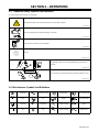
3-2. Miscellaneous Symbols And Definitions
A
Amperes Alternating Current Voltage Input
Circulating Unit
With Coolant Pump
V
Volts
Water (Coolant) In-
put
Water (Coolant)
Output
Line Connection
Protective Earth
(Ground)
IP
Degree Of
Protection
I
1
Primary Current
Hz
Hertz
On Off
U
1
Primary Voltage Single Phase

OM-6608 Page 6
SECTION 4 − SPECIFICATIONS
4-1. Serial Number And Rating Label Location
The serial number and rating information for this product is located on the back panel. Use rating label to determine input power requirements and/or
rated output. For future reference, write serial number in space provided on cover of this manual.
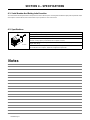
4-2. Specifications
801 189-C
Recirculating Coolant System For Water-Cooled GTAW Torches And GMAW Guns
Use With Guns/Torches Rated Up To 600 Amperes
IP Rating: 23
3 gal (11.4 L) Coolant Tank Capacity;
Maximum Cooling Capacity: 14,000 BTU/hr At 1.25 qt/min (1.2 L/min)
Dimensions: 23 in. (584 mm) Long, 12 in. (305 mm) Wide, 13-1/4 in. (337 mm) High
Weight: 39 lb (18 kg)
115 Volt Models Use 5.9 Amperes, 50/60 Hertz, Single-Phase Input Power
230 Volt Models Use 3 Amperes, 50/60 Hertz, Single-Phase Input Power
Notes

OM-6608 Page 7
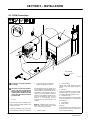
SECTION 5 − INSTALLATION
5-1. GTAW Connections
801 190-D
! Do not move or operate unit where
it could tip.
! 230 volt AC coolers only: Replace
power cord plug if supplied plug
does not match receptacle. Have a
qualified person install correct 230
volt AC plug according to national
and local codes.
1 Lift -Eye
If placing cooling unit on welding power
source, slots are provided in bottom of unit
so it fits over lift-eye.
To prevent overheating, make sure cooling
unit is positioned so airflow is not restricted.
2 115 Or 230 Volt AC Grounded Re-
ceptacle (Depending On Model)
An individual branch circuit capable of car-
rying 15 amperes and protected by fuses or
circuit breakers is recommended. Recom-
mended fuse or circuit breaker size is 15
amperes. For 230 volt models, an individu-
al branch circuit capable of carrying 10 am-
peres and protected by fuses or circuit
breakers is recommended. Recom-
mended fuse or circuit breaker size is 10
amperes.
NOTICE − If welding power source has a
water valve, do not connect hoses to water
valve. Connect hoses as shown.
3 Coolant Out Hose
4 Coolant In Hose
Fittings have 5/8-18 left-hand threads.
Connect hoses with proper fittings as
shown.
5 TIG Block
Customer supplied for use with some weld-
ing power sources, or use proper connec-
tor supplied with welding power source.
6 Coolant Tank Cap
Remove cap and fill tank. Maintain coolant
level at approximately 1 in. (25 mm) below
top of filler neck.
7 Flow Indicator
8 Power Switch
Operation:
Turn power switch On. Flow indicator spins
to indicate that at least 0.53 qt/min (0.5
L/min) of coolant is flowing.
1
Tools Needed:
5/8 in.
3
4
6
7
8
5
2

OM-6608 Page 8
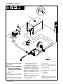
5-2. GMAW Connections
801 191-D
Tools Needed:
5/8 in.
! Do not move or operate unit where
it could tip.
! 230 volt AC coolers only: Replace
power cord plug if supplied plug
does not match receptacle. Have a
qualified person install correct 230
volt AC plug according to national
and local codes.
1 Lift -Eye
If placing cooling unit on welding power
source, slots are provided in bottom of unit
so it fits over lift-eye.
To prevent overheating, make sure cooling
unit is positioned so airflow is not restricted.
2 115 Or 230 Volt AC Grounded Re-
ceptacle (Depending On Model)
An individual branch circuit capable of car-
rying 15 amperes and protected by fuses
or circuit breakers is recommended. Rec-
ommended fuse or circuit breaker size is
15 amperes. For 230 volt models, an indi-
vidual branch circuit capable of carrying 10
amperes and protected by fuses or circuit
breakers is recommended. Recom-
mended fuse or circuit breaker size is 10
amperes.
NOTICE − If welding power source has a
water valve, do not connect hoses to water
valve. Connect hoses as shown.
3 Coolant Out Hose
4 Coolant In Hose
Fittings have 5/8-18 left-hand threads.
Connect hoses with proper fittings as
shown.
5 Coolant Tank Cap
Remove cap and fill tank. Maintain coolant
level at approximately 1 in. (25 mm) below
top of filler neck.
6 Flow Indicator
7 Power Switch
Operation:
Turn power switch On. Flow indicator spins
to indicate that at least 0.53 qt/min (0.5
L/min) of coolant is flowing.
3
4
5
6
7
1
2

OM-6608 Page 9
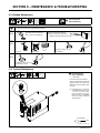
SECTION 6 − MAINTENANCE & TROUBLESHOOTING
6-1. Routine Maintenance
! Disconnect power
before maintaining.
n = Check Z = Change ~ = Clean Δ = Repair l = Replace
* To be done by Factory Authorized Service Agent
Every
3
Months
~Coolant Filter, durning heavy
service, clean more frequently.
~ Blow out heat exchanger fins.
nCheck coolant level. Top off with
distilled or deionized water if necessary.
Every
6
Months
nlHoses
nl Labels
ZReplace Coolant. (If
Using Water)
Every
12
Months
ZReplace Coolant. (If Using
Commercial Coolant)
3/8 in.
Tools Needed:
6-2. Coolant Maintenance
801 189-C / Ref. 801 194
! Disconnect power
before maintaining.
1 Coolant Filter
Unscrew housing to clean filter.
Changing coolant: Drain coolant by
tipping unit forward. Fill with clean
water and run for 10 minutes. Drain
and refill.
. If replacing hoses, use hoses
compatible with ethylene gly-
col, such as Buna-n, Neo-
prene, or Hypalon. Oxy-acety-
lene hoses are not compatible
with any product containing
ethylene glycol.
1

OM-6608 Page 10
6-3. Troubleshooting
Trouble Remedy
Coolant system does not work. Be sure input power cord is plugged in to energized receptacle.
Check line fuses or circuit breaker, and fuses F1, F2 if applicable, and replace or reset if necessary.
Motor overheated. Unit starts running when motor has cooled.
Have Factory Authorized Service Agent check Power switch S1 and motor Mot.
Decreased or no coolant flow. Add coolant.
Check for clogged hoses or coolant filter. Clean filter or clean / replace hoses if necessary.
Disconnect pump, and check for sheared coupling. Replace coupling if necessary.
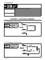
SECTION 7 − ELECTRICAL DIAGRAM
7-1. Circuit Diagram For 115 Volt Cooler
135 796-D
7-2. Circuit Diagram For 230 Volt Cooler
187 733-A

OM-6608 Page 11
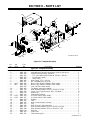
SECTION 8 − PARTS LIST
*Included in Item 24
1
2
3
6
4
5
7
8
9
10
11
12
13
14
15
16
11
17
18
19
20
21
22
18
26
11
21
25
24
11
11
22
23
29
28
27
26
Figure 8-1. Complete Assembly
Description
Part
No.
Dia.
Mkgs.
Item
No.
Figure 8-1. Complete Assembly
Quantity
1 BWC-001 Hood 1... .......... ..... ..........................................................
2 BWC-040 Label,Warning General Precautionary Static (Eng/French) 1... .......... ..... ............
3 BWC-002 Pump Coolant w/Fittings (Includes) 1... .......... ..... ................................
4 BWC-003 FTG, Hose BRS Barbed Elbow M 3/8 TBG x 3/8 NPT 2... .......... ....... ..............
5 BWC-004 Drive Pump Coupler 1... .......... ....... ...........................................
6 BWC-005 Hose Fitting 1... .......... ....... ..................................................
7 BWC-006 Hose Clamp, .375 − .450 clip 1... .......... ..... .....................................
8 BWC-007 No. 1 Braided HOSE (1/4” ID) 1... .......... ..... ....................................
9 MOT BWC-008 Motor, 1/4hp 115VAC 50/60Hz (115V model) 1... ... . ..... ........................
9 MOT BWC-026 Motor, 1/4hp 230VAC 50/60Hz (230V model) 1... ... . ..... .......................
BWC-039 Fuse, 7A 250V (230V model) 1................ ..... .....................................
10 BWC-009 Fan Blade, (setscrew included) 1... .......... ..... ...................................
11 BWC-010 Hose, Rubber Braided .375 ID x .650 OD x 17.000 2... .......... ..... ..................
12 BWC-046 Clamp, 1-Ear Type Nom Dim .718 x .276 Wide 10... .......... ..... .....................
13 BWC-012 Rear Panel 1... .......... ..... .....................................................
14 BWC-013 Strain Relief Bushing 1... .......... ..... ............................................
15 PLG1 BWC-014 10’ Power Cable (115V model) 1... .. . ..... ....................................
15 PLG1 BWC-027 10’ Power Cable, (230V model) 1... .. . ..... ...................................
16 BWC-015 Radiator 1... .......... ..... .......................................................
17 BWC-047 Tank 1... .......... ..... ...........................................................
18 BWC-035 Hose, Coolant Return w/Clamp 1... .......... ..... ...................................
19 BWC-017 Cap 1... .......... ..... ...........................................................
20 BWC-036 Hose, Pick-up Coolant w/Clamp 1... .......... ..... ...................................
21 BWC-037 Hose, Rubber Braided .375 ID x .650 OD x 10.500 1... .......... ..... ..................
22 BWC-048 Hose, Rubber Braided .375 ID x .650 OD x 3.750 1... .......... ..... ...................
23 BWC-019 Ring Clip 2... .......... ..... .......................................................
24 BWC-020 In-line Filter 1... .......... ..... ....................................................
25 BWC-021 Filter Mounting Clip 1... .......... ..... ..............................................

OM-6608 Page 12
Description
Part
No.
Dia.
Mkgs.
Item
No.
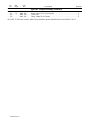
Figure 8-1. Complete Assembly (Continued)
Quantity
26 BWC-049 Flow Indicator 1... .......... ..... ..................................................
27 S1 BWC-023 Rocker Switch DPST 15A 250 VAC 1... .... .. ..... ................................
28 BWC-024 Front Panel 1... .......... ..... ....................................................
29 BWC-025 Fitting, 3/8tbg 5/8-18 Female 2... .......... ..... .....................................
BE SURE TO PROVIDE MODEL AND SERIAL NUMBER WHEN ORDERING REPLACEMENT PARTS.

Notes

ORIGINAL INSTRUCTIONS − PRINTED IN USA 2013−01
Model Name Serial/Style Number
Purchase Date (Date which equipment was delivered to original customer.)
Distributor
Address
City
State Zip
Please complete and retain with your personal records.
Always provide Model Name and Serial/Style Number.
Contact your Distributor for: Welding Supplies and Consumables
Options and Accessories
Personal Safety Equipment
Service and Repair
Replacement Parts
Owner’s Manuals
Circuit Diagrams
Contact the Delivering Carrier to:
Resources Available
Owner’s Record
File a claim for loss or damage during
shipment.
For assistance in filing or settling claims, contact
your distributor and/or equipment manufacturer’s
Transportation Department.
-
 1
1
-
 2
2
-
 3
3
-
 4
4
-
 5
5
-
 6
6
-
 7
7
-
 8
8
-
 9
9
-
 10
10
-
 11
11
-
 12
12
-
 13
13
-
 14
14
-
 15
15
-
 16
16


Miller BWC-3 Le manuel du propriétaire
- Catégorie
- Système de soudage
- Taper
- Le manuel du propriétaire
- Ce manuel convient également à
dans d''autres langues
- English: Miller BWC-3 Owner's manual
Documents connexes
-
Miller MG050034L Le manuel du propriétaire
-
-
-
-
-
-
Miller Coolmate 1 Le manuel du propriétaire
-
Miller Coolmate 3 Le manuel du propriétaire
-
-