Hydromatic HVR 100 Series Grinder Pump Le manuel du propriétaire
- Taper
- Le manuel du propriétaire

pentair.com
INSTALLATION AND
OPERATION MANUAL
HVR 100 SERIES GRINDER PUMPS
HYD01-1111 (12-01-2020) ©2020 Pentair. All Rights Reserved.
ENGLISH: 1 -12 FRANCAIS: 13-24

2 HYD01-1111 (12-01-20)
TABLE OF CONTENTS
Safety Information ................................................................................................................................................................................ 3
Overview & Installation .........................................................................................................................................................................4
Maintenance .........................................................................................................................................................................................5
Parts List .............................................................................................................................................................................................. 7
Troubleshooting ....................................................................................................................................................................................9
Limited Warranty ................................................................................................................................................................................. 11

3
HYD01-1111 (12-01-20)
SAFETY INFORMATION
SAVE THESE INSTRUCTIONS: This manual contains important
instructions that should be followed during installation,
operation, and maintenance of the product. Carefully read and
follow all safety instructions in this manual.
IMPORTANT SAFETY TERMINOLOGY
indicates a hazard which, if not avoided, will result
in death or serious injury.
indicates a hazard which, if not avoided, can result
in death or serious injury.
indicates a hazard which, if not avoided, can or
may result in minor or moderate injury.
NOTE addresses practices not related to personal injury.
SAFETY WARNINGS
Hazardous Voltage. Can cause severe or fatal
electrical shock. Do not plug in or unplug while standing on a
wet floor or in water. Failure to follow this warning can result in
fatal electrical shock.
Risk of flooding. Do not run pump dry. To do so
will damage seals and can cause leaking and property damage.
Risk of electrical shock. Do not lift the pump by
the electrical cord; lift pump only by the discharge pipe, lifting
ring or handle on the pump. Lifting by the cord can damage the
cord.
CALIFORNIA PROPOSITION 65 WARNING
This product and related accessories contain
chemicals known to the State of California to cause cancer,
birth defects or other reproductive harm.
Risk of electrical shock. Pumps are supplied with
a grounding conductor and grounding-type attachment plug on
the power cord. To reduce the risk of electrical shock, be
certain that it is connected only to properly grounded,
grounding-type receptacle. DO NOT cut off ground pin or use an
adapter fitting. DO NOT use an extension cord with this pump.
When wiring this pump follow all local electrical, safety codes
and ordinances as well as most recent National Electric Code
(NEC-ANSI/NFPA).
The HVR100 Series grinder pumps have a GROUND WIRE that is
connected to a screw in the metal motor housing. This wire goes
to the receptacle or control box which must be connected to a
good outside GROUND such as a metal water pipe or GROUND
STAKE driven at least 8 feet into the ground.
To the installer: Please make sure you provide this manual to
the owner of the equipment or to the responsible party who
maintains the system

4 HYD01-1111 (12-01-20)
OVERVIEW & INSTALLATION
USAGE
The HVR100 Series is a submersible wastewater grinder pump
designed specifically for individual residential applications. The
pumps are to be used for domestic sewage only and are not to
be used for pumping commercial or industrial sewage such as
from motels, schools, apartments, factories, etc. This pump is
not for use in hazardous locations!
INSPECTING PUMP
Before making any piping or electrical connections, check
the pump for shipping damage or cracks. Insert allen key into
cutter retaining bolt and turn clockwise to ensure cutters and
impellers do not rub. Do not turn cutter with fingers.
POWER SUPPLY
The HVR100 Series grinder pump should be connected to a 115 or
230 volt, single-phase, 60 Hz power source. The pump will draw
approximately 7.4, 5.3 amperes at minimum flow and 12.5, 7.6
full load amperes. The pump must be connected to a grounded
power socket. DO NOT cut off the ground pin from the power
cord plug.
POWER CORD
A 20 foot power cord is attached to the grinder pump via two
insulated quick-disconnect terminals and a ground terminal. To
replace a cord, begin by slightly loosening cord nut in the cord
cap plate. Remove cord cap plate from the motor housing and
carefully pull the power leads up out of the motor housing and
disconnect them from the motor leads. Disconnect the ground
wire from the cap plate and continue to completely loosen the
cord nut from the cap.
To install new cord, feed terminals through cord cap plate and
reconnect power terminals. Reconnect ground terminal to the
bottom side of the cap plate. Carefully feed wires back into
the motor housing and fasten the cord cap plate to the motor
housing. Lastly, tighten the cord nut into the cap plate. Tighten
firm, do not overtighten.
The power cord should be replaced if it has been damaged in any
way or the cord jacket has become brittle.
MOTOR TYPE
The HVR100 Series grinder pump contains a 3/4 frame, 1 hp,
single-phase, 60 Hz, 3450 rpm, capacitor start, capacitor run
motor with Class F insulation and built-in, on-winding overload
protection. Motor has upper and lower ball bearings and is oil-
cooled and lubricated.
The HVR 100 Series grinder pump should never
be worked on without first disconnecting the power cord.
OIL TYPE
The motor housing contains dielectric transformer oil to provide
good heat transfer and lubrication of ball bearings; no other
lubrication is required. Oil level may be checked by removing the
oil plug from the top of the motor housing. The oil level should
be filled to the bottom of the end shield. Do not overfill with oil.
Only dielectric transformer oil obtained from a Hydromatic®
authorized service center should be used.
PUMP SWITCH INSTALLATION INSTRUCTIONS
NOTE: In accordance with third party approval, pump must be
submerged a minimum of 8-5/8” from bottom of the legs on
volute case during operation.
Mounting the Switch
1. Determine pumping range for installation. Do not tether
less than 3-1/2” from pipe.
2. Tighten strap around discharge pipe keeping switch cable
between strap and pipe to prevent slippage.
3. Space small ties at least 1” apart. To readjust ties, press
small tie tabs down.
4. To lock releasable tab, run remaining strap between tab and
head. Tuck strap back through head.
Piggyback Plug Install
Electrical outlet must not be located in pump chamber.
Electrical outlet voltage, piggyback plug voltage, and pump
voltage must match.
1. Follow steps 1 through 4 of “Mounting the Switch.”
2. Insert switch’s piggyback plug into outlet.
3. Plug pump into piggyback plug.
4. Check installation. Allow system to cycle to ensure proper
operation.

5
HYD01-1111 (12-01-20)
DISMANTLING PUMP FOR REPLACEMENT PARTS
Before dismantling pump for replacement parts, clean pump
thoroughly.
REPLACING STATIONARY CUTTER PLATE AND ROTATING
CUTTER
All repairs must be done at the factory or at an authorized
Hydromatic service facility.
Disconnect all power and control wires to motor
at control panel before starting disassembly operations.
Never rely on opening circuit breaker only.
DISASSEMBLY OF STATIONARY CUTTER PLATE AND ROTATING
CUTTER
1. Remove retaining washer and screw from end of shaft.
A screwdriver can be used to hold the shaft in place by
wedging it between one of the four socket head cap screws
and the rotating cutter while loosening the screw.
2. Using a rubber mallet, or soft metal hammer, bump rotating
cutter in counterclockwise direction as thread is right-
hand. Unthread rotating cutter from shaft. Be careful to
not lose ring shims that space the rotating cutter from the
stationary cutter plate.
3. Remove four socket head cap screws holding the stationary
cutter plate to the volute. Remove stationary cutter from
volute. If stationary cutter is stuck, the socket head cap
screws can be threaded into tapped back-off hole in plate.
Tighten screws to remove plate from volute.
4. Inspect rotating cutter and stationary cutter plate for wear
and replace if worn.
5. Make sure pocket in volute is clean and reinstall stationary
cutter plate using the four socket head cap screws. Apply
blue Loctite® to the threads. Do not overtighten cap
screws.
6. Replace ring shims (if removed from the shaft) and thread
rotating cutter onto shaft. Make sure threads on shaft are
clean and use Never-Seez® or other graphite compound on
threads before replacing rotating cutter.
7. Using a rubber mallet, or soft metal hammer, bump rotating
cutter in clockwise direction to make sure it is seated on
the impeller.
8. To ensure proper operation of the cutter mechanism, the
gap between the stationary cutter plate and rotating cutter
must be no more than .008”. To check the gap use a .008”
feeler gauge. If the .008” feeler gauge does not fit between
the surface of the stationary cutter and rotating cutter and
the motor shaft turns freely, the gap is set correctly. If the
.008” feeler gauge fits between the surfaces, shims must
be removed to close the gap
9. Replace retaining washer and screw in the end of the shaft.
Be sure screw is tight. A screwdriver can be used to hold the
shaft in place by wedging it between one of the four socket
head cap screws and the rotating cutter while tightening
the screw.
10. Be sure shaft turns freely after reassembly. Some drag will
occur due to the seal, but there should be no binding or tight
spots when turning the rotating cutter.
11. If rotating cutter rubs or drags on stationary cutter plate,
recheck gap and re-shim rotating cutter.
TO REPLACE CAPACITORS ONLY
1. Remove oil fill plug near the top of motor housing and pour
oil out.
2. Loosen the cord nut on power cord until cord is loose
enough to push cord down into motor housing.
3. Remove four bolts from motor housing and bump housing
with a plastic hammer to loosen. Lay pump on its side.
4. Remove the housing carefully to be sure that enough cord is
pushed into the housing so as not to create tension on cord.
5. Slide motor housing up far enough to expose the capacitors
and to be able to lay the housing down.
6. Disconnect wiring from capacitor and loosen capacitor
clamp and slide capacitor out. Replace with new capacitor,
tighten clamp and reconnect.
7. Check all wiring connectors to be sure they are secure.
8. Be sure O-ring is in place.
9. Slide motor housing back onto pump while pulling the cord
out slowly. Assemble motor housing with four bolts.
10. Reassemble cord nut. Be sure washers are seated and cord
is pulled up against the washers. Tighten nut securely.
11. Put pump upright and refill motor with Hydromatic
submersible pump oil. DO NOT OVERFILL WITH OIL.
Replace oil plug. Retighten plug firmly, but do not
overtighten.
12. Be sure pump turns freely before connecting power. Turn
pump on side and turn impeller, using screwdriver in slotted
shaft. Plug pump into receptacle to test operation. Pump
must run quietly and free of vibration.
MAINTENANCE

6 HYD01-1111 (12-01-20)
MAINTENANCE
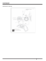
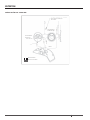
WIRING DIAGRAM – MARATHON®
Run Capacitor
Insulated Terminals
Non - Insulated Terminals
Start
Capacitor
Black Screw on Motor
End Bell
White
Yellow
Ground (Green)
Line 2 (White)
Line 1 (Black)
Red

7
HYD01-1111 (12-01-20)
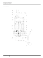
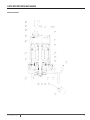
REPAIR PARTS LIST
MOTOR END PARTS
B2
A4 A10 A7
A9
A1
A6
A12
A13
A2
A3
A6C1
C5
D1
C3C4C2
B1
B4
B3
A14
A11
A7
A6

8 HYD01-1111 (12-01-20)
REPAIR PARTS LIST
Item # Description Qty Component Part #
A1 Motor Housing 128132B000
A2 Bearing/Seal Housing 128169B000
A3 Case, Volute 128170D001
A4 Handle, Neoprene Grip 128196B000
A5 Impeller, Thermoplastic 128185B000
A6 Canned Motor Assembly 1CHARTED
A7 5/16 -18 x 1” Screw 12 001780041
A8 10-24 Screw 4048200061
A9 1/4 Pipe Plug 1 05022A088
A10 Washer 205030A020
A11 O-ring 1/8 x 5.859 1 05876A125
A12 Retaining Ring, Internal 1009740081
A13 Seal 7/8 Shaft 21/BF501C1 1 21576A011
A14 Oil, Transformer .625 gal 132531001
B1 Plate, Cord Cap 1 28193B000
B2 Cord; 14/3 with Moulded Plug 1 CHARTED
B3 Ground Screw 1000630021
B4 O-ring 105876A244
C1 Stationary Cutter 128168B000
C2 Rotating Cutter 128187B000
C3 Retaining Washer 121583A000
C4 Retaining Screw 107597A013
C5 Shim; 1.00 O.D. x .625 I.D. x .002 1 006280571
Shim; 1.00 O.D. x .625 I.D. x .020 1 006280591
Shim; 1.00 O.D. x .625 I.D. x .030 1 006280601
Shim; 1.00 O.D. x .625 I.D. x .005 1 006280581
D1 230V 1145950201
115V 1145951201
Pump Catalog
Number
Pump Engineering
Number Pump Type Cord Number Cord Length Motor Number
Automatic 25338B000 20’ 28167B000
Manual 25338B000 20’ 28167B001
Automatic 25338B001 20’ 28167B000
Manual 25338B001 20’ 28167B001

9
HYD01-1111 (12-01-20)
TROUBLESHOOTING
TROUBLESHOOTING GUIDE
Pump does not run or hum.
See A, B, C, D, E or F. A. Line circuit breaker may be off; or fuse, if used, may be blown or loose.
Pump runs but does not deliver water.
See G, H, I, J, K or L. B. Water level in sump may be too low. Run in more water.
Pump runs and pumps out sump but does not stop.
See M. C. Pump cord plug may not be making contact in receptacle.
Pump runs but delivers only small amount of water.
See I, J, K, L or N.
D. If pump is using the series cord plug, the two plugs may not be plugged
tightly together.
Fuse blows or circuit breaker trips when pump starts.
See K, L, N, O or P.
E. Float may be stuck. Be sure oat operates freely in basin. Check tether
length of switch.
Motor runs for short time then stops. Then after short period starts
again. Indicates tripping overload caused by symptom shown.
See K, L, N or P.
F. If all symptoms check OK, motor winding may be open;take to service
center for repair.
For any other symptoms contact a Myers authorized service facility. G. Check valve may be installed backward. Arrow on valve points in
direction of ow.
H. Discharge shut-off valve, if used, may be closed.
I. Pump may be air locked. Start and stop several times by plugging and
unplugging cord. Check vent hole on pump case for plugging.

10 HYD01-1111 (12-01-20)
THIS PAGE INTENTIONALLY LEFT BLANK

11
HYD01-1111 (12-01-20)
WARRANTY
Pentair Hydromatic* warrants its products against defects in material and workmanship for a period of 12 months
from installation date or 18 months from manufacturing date, whichever occurs rst – provided that such products
are used in compliance with the requirements of the Pentair Hydromatic catalog and technical manuals for use in
pumping raw sewage, municipal wastewater or similar, abrasive-free, noncorrosive liquids.
During the warranty period and subject to the conditions set forth, Pentair Hydromatic, at its discretion, will repair
or replace to the original user, the parts that prove defective in materials and workmanship. Pentair Hydromatic
reserves the right to change or improve its products or any portions thereof without being obligated to provide such
a change or improvement for prior sold and/or shipped units.
Start-up reports and electrical schematics may be required to support warranty claims. Submit at the time of start
up through the Pentair Hydromatic website: http://forms.pentairliterature.com/startupform/startupform.asp?
type=h. Warranty is effective only if Pentair Hydromatic authorized control panels are used. All seal fail and heat
sensing devices must be hooked up, functional and monitored or this warranty will be void. Pentair Hydromatic will
cover only the lower seal and labor thereof for all dual seal pumps. Under no circumstance will Pentair Hydromatic be
responsible for the cost of eld labor, travel expenses, rented equipment, removal/reinstallation
costs or freight expenses to and from the factory or an authorized Pentair Hydromatic service facility.
This limited warranty will not apply: (a) to defects or malfunctions resulting from failure to properly install, operate
or maintain the unit in accordance with the printed instructions provided; (b) to failures resulting from abuse, acci-
dent or negligence; (c) to normal maintenance services and parts used in connection with such service; (d) to units
that are not installed in accordance with applicable local codes, ordinances and good trade practices; (e) if the unit
is moved from its original installation location; (f) if unit is used for purposes other than for what it is designed and
manufactured; (g) to any unit that has been repaired or altered by anyone other than Pentair
Hydromatic or an authorized Pentair Hydromatic service provider; (h) to any unit that has been repaired using non
factory specied/OEM parts.
Warranty Exclusions: PENTAIR HYDROMATIC MAKES NO EXPRESS OR IMPLIED WARRANTIES THAT EXTEND BE-
YOND THE DESCRIPTION ON THE FACE HEREOF. PENTAIR HYDROMATIC SPECIFICALLY DISCLAIMS THE IMPLIED
WARRANTIES OF MERCHANTABILITY AND FITNESS FOR ANY PARTICULAR PURPOSE.
Liability Limitation: IN NO EVENT SHALL PENTAIR HYDROMATIC BE LIABLE OR RESPONSIBLE FOR CONSEQUEN-
TIAL, INCIDENTAL OR SPECIAL DAMAGES RESULTING FROM OR RELATED IN ANY MANNER TO ANY PENTAIR HY-
DROMATIC PRODUCT OR PARTS THEREOF. PERSONAL INJURY AND/OR PROPERTY DAMAGE MAY RESULT FROM
IMPROPER INSTALLATION. PENTAIR HYDROMATIC DISCLAIMS ALL LIABILITY, INCLUDING LIABILITY UNDER THIS
WARRANTY, FOR IMPROPER INSTALLATION. PENTAIR HYDROMATIC RECOMMENDS INSTALLATION BY PROFES-
SIONALS.
Some states do not permit some or all of the above warranty limitations or the exclusion or limitation of incidental
or consequential damages and therefore such limitations may not apply to you. No warranties or representations
at any time made by any representatives of Pentair Hydromatic shall vary or expand the provision hereof.

293 Wright Street,
Delavan, WI 53115
USA
Ph: 888.957.8677
Fax: 800.426.9446
490 Pinebush Road
Unit 4
Cambridge, Ontario N1T 0A5
Canada
Ph: 800.363.7867
Orders Fax: 888.606.5484
pentair.com
For a detailed list of where Pentair trademarks are registered, please visit www.pentair.com/en/registrations.html. All indicated Pentair trademarks and logos are property of Pentair.
Third party registered and unregistered trademarks and logos are the property of their respective owners. Because we are continuously improving our products and services, Pentair
reserves the right to change specications without prior notice. Pentair is an equal opportunity employer.
HYD01-1111 (12-01-20) ©2020 Pentair. All Rights Reserved.

pentair.com
MANUEL D’INSTALLATION
ET D’UTILISATION
POMPES BROYEUSES SÉRIE HVR 100
HYD01-1111 (01-12-2020) © 2020 Pentair. Tous droits réservés.

14 HYD01-1111 (12-01-20)
TABLE DES MATIÈRES
Consignes de sécurité .......................................................................................................................................................................... 15
Aperçu et installation ...........................................................................................................................................................................16
Entretien ..............................................................................................................................................................................................17
Liste des pièces ...................................................................................................................................................................................19
Dépannage ...........................................................................................................................................................................................21
Garantie limitée .................................................................................................................................................................................. 23

15
HYD01-1111 (12-01-20)
CONSIGNES DE SÉCURITÉ
CONSERVEZ CES CONSIGNES: Ce manuel contient des
consignes importantes qui doivent être suivies pendant
l’installation, l’utilisation et l’entretien du produit. Lisez
attentivement et suivez toutes les consignes de sécurité
figurant dans ce manuel.
TERMINOLOGIE DE SÉCURITÉ IMPORTANTE
indique un danger qui entraînera la mort
ou des blessures graves s’il n’est pas évité.
MISE EN GARDE indique un danger qui peut entraîner la mort
ou des blessures graves s’il n’est pas évité.
ATTENTION
indique un danger qui peut ou pourrait entraîner
des blessures légères ou moyennement graves s’il n’est pas évité.
REMARQUE concerne des pratiques non liées aux lésions
corporelles.
MISES EN GARDE DE SÉCURITÉ
MISE EN GARDE
Tension dangereuse. Peut provoquer un
choc électrique grave ou mortel. Ne pas brancher ou
débrancher lorsque vous vous trouvez sur un plancher mouillé
ou dans l’eau. Le non-respect de cette mise en garde peut
entraîner un choc électrique mortel.
ATTENTIONRisque d’inondation. Ne pas faire fonctionner
la pompe à sec. Cela endommagera les joints et peut provoquer
des fuites et des dommages matériels.
MISE EN GARDE
Risque de choc électrique. Ne pas soulever
la pompe par le cordon électrique; la soulever uniquement par le
tuyau d’évacuation, l’anneau de levage ou la poignée de la pompe.
Soulever la pompe par le cordon peut endommager ce dernier.
AVERTISSEMENT CONCERNANT LA PROPOSITION 65
DE LA CALIFORNIE
MISE EN GARDE
Ce produit et les accessoires connexes
contiennent des produits chimiques considérés par l’État de
la Californie comme pouvant causer le cancer, des anomalies
congénitales ou d’autres troubles du système reproducteur.
MISE EN GARDE Risque de choc électrique. Les pompes sont
équipées d’un conducteur de mise à la terre et d’un système
de raccord pour mise à la terre se trouvant sur le cordon
d’alimentation. Pour réduire le risque de choc électrique,
s’assurer qu’elle est bien branchée à un réceptacle correctement
mis à la terre. NE PAS couper la broche de terre ou utiliser un
raccord d’adaptateur. NE PAS UTILISER de rallonge avec cette
pompe. Lors du câblage de cette pompe, respecter tous les
codes et ordonnances locaux en matière d’électricité et de
sécurité, ainsi que le code électrique national le plus récent
(NEC-ANSI/NFPA).
Les pompes broyeuses série HVR100 disposent d’un
FIL DE TERRE qui est relié à une vis dans le boîtier métallique
du moteur. Ce fil va à la prise ou à la boîte de commande qui
doit être raccordée à un élément extérieur AU SOL tel qu’une
conduite d’eau en métal ou un PIEU DE TERRE enfoncé
d’au moins 2 mètres dans le sol.
À l’installateur : Veuillez vous assurer de fournir ce manuel
au propriétaire de l’équipement ou à la partie responsable
qui assure l’entretien du système.

16 HYD01-1111 (12-01-20)
APERÇU ET INSTALLATION
UTILISATION
La série HVR100 est une pompe broyeuse submersible des
eaux usées conçue spécifiquement pour les applications
résidentielles individuelles. Les pompes doivent être utilisées
pour les eaux usées domestiques uniquement et ne doivent pas
être utilisées pour le pompage des eaux usées commerciales
ou industrielles telles que celles des motels, des écoles, des
appartements, des usines, etc. Cette pompe n’est pas destinée
à être utilisée dans des endroits dangereux!
INSPECTION DE LA POMPE
Avant d’effectuer des raccordements de tuyauterie ou électriques,
vérifier si la pompe n’a pas été endommagée ou fissurée lors du
transport. Insérer la clé Allen dans le boulon de retenue de pince
coupante et tourner dans le sens des aiguilles d’une montre
pour vous assurer que les pinces coupantes et les impulseurs ne
frottent pas. Ne pas tourner la pince coupante avec les doigts.
BLOC D’ALIMENTATION
La pompe broyeuse série HVR100 doit être raccordée à une
source de courant monophasée de 115 ou 230 volts, à 60 Hz.
La pompe tirera environ 7,4, 5,3 ampères au débit minimum et
12,5, 7,6 ampères à pleine charge. La pompe doit être raccordée
à une prise de courant mise à la terre. NE PAS couper la broche
de terre de la prise du cordon d’alimentation.
CORDON D’ALIMENTATION
Un cordon d’alimentation de 20 pieds est relié à la pompe
broyeuse par deux bornes isolées à détachement rapide et
une borne de terre. Pour remplacer un cordon, commencer
par desserrer légèrement l’écrou du cordon dans la plaque
du capuchon de cordon. Retirer la plaque du capuchon du
cordon du boîtier du moteur et tirer avec précaution les fils
d’alimentation vers le haut hors du boîtier du moteur et les
détacher des fils du moteur. Débrancher le fil de terre de la
plaque du capuchon et continuer à desserrer complètement
l’écrou du cordon du capuchon.
Pour installer un nouveau cordon, faire passer les bornes à
travers la plaque de recouvrement du cordon et rebrancher
les bornes d’alimentation. Raccorder la borne de terre à la
face inférieure de la plaque de recouvrement. Repasser
soigneusement les fils dans le boîtier du moteur et fixer la
plaque du capuchon du cordon sur le boîtier du moteur.
Enfin, serrer l’écrou du cordon dans la plaque du capuchon.
Serrer bien, mais ne pas trop serrer.
Le cordon d’alimentation doit être remplacé s’il a été
endommagé de quelque manière que ce soit ou si la gaine
du cordon est devenue cassante.
TYPE DE MOTEUR
La pompe broyeuse série HVR100 contient un moteur de 3/4
de châssis, 1 CV, monophasé, 60 Hz, 3450 tr/min, démarrage
par condensateur, moteur à condensateur avec isolation de
classe F et protection intégrée contre les surcharges en cours
de bobinage. Le moteur comporte des roulements à billes
supérieurs et inférieurs et est refroidi et lubrifié à l’huile.
ATTENTION
Il ne faut jamais travailler sur la pompe
broyeuse série HVR 100 sans avoir débranché le cordon
d’alimentation au préalable.
TYPE D’HUILE
Le boîtier du moteur contient une huile diélectrique pour
transformateur qui assure un bon transfert de chaleur et une bonne
lubrification des roulements à billes; aucune autre lubrification
n’est nécessaire. Le niveau d’huile peut être vérifié en retirant le
bouchon d’huile situé sur le dessus du boîtier du moteur. Le niveau
d’huile doit être rempli jusqu’au bas du bouclier, sans trop remplir
d’huile. Seule l’huile diélectrique pour transformateur obtenue
auprès d’un centre de service agréé Hydromatic® doit être utilisée.
INSTRUCTIONS D’INSTALLATION DE L’INTERRUPTEUR DE
LA POMPE
REMARQUE: Conformément à l’approbation d’un tiers, la pompe
doit être immergée à un minimum de 85/8po du bas des pattes
sur la volute pendant le fonctionnement.
Installation de l’interrupteur
1. Déterminer la plage de pompage pour l’installation. Ne pas
attacher à moins de 31/2po du tuyau.
2. Serrer la sangle autour du tuyau d’évacuation en gardant
le câble de commutation entre la sangle et le tuyau pour
éviter tout glissement.
3. Espacer les petites attaches à au moins 1po d’intervalle. Pour
réajuster les attaches, appuyer sur les petites languettes.
4. Pour verrouiller la languette libérable, faire passer le reste
de la sangle entre la languette et la tête, puis rentrer la
sangle dans la tête.
Installation de la prise de courant superposable
La prise électrique ne doit pas être située dans la chambre de la
pompe. La tension de la prise électrique, de la prise de courant
et de la pompe doit correspondre.
1. Suivre les étapes 1 à 4 de la section «Installation
de l’interrupteur».
2. Insérer la fiche superposable de l’interrupteur dans la prise
de courant.
3. Brancher la pompe dans la prise superposable.
4. Vérifier l’installation. Permettre au système d’effectuer
un cycle pour assurer un fonctionnement adéquat.

17
HYD01-1111 (12-01-20)
DÉMONTAGE DE LA POMPE POUR LES PIÈCES DE RECHANGE
Avant de démonter la pompe pour remplacer des pièces,
la nettoyer soigneusement.
REMPLACEMENT DE LA PLAQUE DE COUPE FIXE ET DE LA
PINCE COUPANTE ROTATIVE
Toutes les réparations doivent être effectuées à l’usine ou dans
une installation de service Hydromatic autorisée.
ATTENTION
Débrancher tous les fils d’alimentation et de
commande du moteur au panneau de commande avant de
commencer les opérations de démontage. Ne jamais compter
uniquement sur un disjoncteur ouvert.
DÉMONTAGE DE LA PLAQUE DE COUPE FIXE ET DE LA PINCE
COUPANTE ROTATIVE
1. Enlever la rondelle de retenue et la vis de l’extrémité de
l’arbre. Un tournevis peut être utilisé pour maintenir l’arbre
en place en le coinçant entre l’une des quatre vis à tête
creuse et la pince coupante rotative tout en desserrant la vis.
2. À l’aide d’un maillet en caoutchouc ou d’un marteau en métal
mou, frapper la pince coupante rotative dans le sens inverse des
aiguilles d’une montre, car le filetage est à droite. Dévisser la
pince coupante rotative de l’arbre. Veiller à ne pas perdre les cales
qui séparent la pince coupante rotative de la plaque de coupe fixe.
3. Retirer les quatre vis à tête creuse qui maintiennent la plaque
de coupe fixe à la volute. Retirer la pince coupante fixe de la
volute. Si une pince coupante fixe est coincée, les vis à tête
creuse peuvent être enfilées dans le trou filé de la plaque.
Serrer les vis pour retirer la plaque de la volute.
4. Inspecter la pince coupante rotative et la plaque de coupe fixe
pour vérifier leur usure et les remplacer si elles sont usées.
5. S’assurer que la poche dans la volute est propre et
réinstaller la plaque de coupe fixe en utilisant les quatre vis
à tête creuse. Appliquer de la Loctite® bleue sur les filets.
Ne pas trop serrer les vis de fixation.
6. Remplacer les cales annulaires (si elles sont retirées de
l’arbre) et enfiler la pince coupante rotative sur l’arbre.
S’assurer que les filets de l’arbre sont propres et utiliser
Never-Seez® ou un autre composé de graphite sur les filets
avant de remplacer la pince coupante rotative.
7. À l’aide d’un maillet en caoutchouc ou d’un marteau en
métal mou, frapper la pince coupante rotative dans le sens
des aiguilles d’une montre pour vous assurer qu’elle est
bien en place sur la roue.
8. Pour assurer le bon fonctionnement du mécanisme de coupe,
l’espace entre la plaque de la pince coupante fixe et la pince
coupante rotative ne doit pas dépasser 0,008po. Pour vérifier
l’écart, utiliser une jauge d’épaisseur de 0,008po. Si la jauge
d’épaisseur de 0,008po ne s’insère pas entre la surface de pince
coupante fixe et celle de la pince coupante rotative et que l’arbre
du moteur tourne librement, l’écart est réglé correctement. Si
la jauge d’épaisseur de 0,008po s’insère entre les surfaces, des
cales doivent être retirées pour combler l’écart.
9. Remplacer la rondelle de retenue et visser l’extrémité de
l’arbre. S’assurer que la vis est bien serrée. Un tournevis
peut être utilisé pour maintenir l’arbre en place en le
coinçant entre l’une des quatre vis à tête creuse et la pince
coupante rotative tout en serrant la vis.
10. S’assurer que l’arbre tourne librement après le remontage.
Une certaine traînée se produira en raison du joint, mais il
ne doit pas y avoir de points d’attache ou d’étranglement
lorsque l’on tourne la pince coupante rotative.
11. Si la pince coupante rotative frotte ou traîne sur une plaque
de coupe fixe, vérifier à nouveau l’écart et caler à nouveau
la pince coupante rotative.
POUR REMPLACER UNIQUEMENT LES CONDENSATEURS
1. Retirer le bouchon de remplissage d’huile situé près du haut
du boîtier du moteur et verser l’huile.
2. Desserrer l’écrou du cordon d’alimentation jusqu’à ce que
le cordon soit suffisamment lâche pour pousser le cordon
dans le boîtier du moteur.
3. Retirer les quatre boulons du boîtier du moteur et frapper
le boîtier avec un marteau en plastique pour le desserrer.
Poser la pompe sur le côté.
4. Retirer le boîtier avec précaution pour vous assurer que
suffisamment de cordon est poussé dans le boîtier afin de
ne pas créer de tension sur le cordon.
5. Faire glisser le boîtier du moteur vers le haut suffisamment loin
pour exposer les condensateurs et pouvoir poser le boîtier.
6. Débrancher le câblage du condensateur, desserrer la pince
du condensateur et faire glisser le condensateur vers
l’extérieur. Le remplacer par un nouveau condensateur,
resserrer la pince et remettre les raccords.
7. Vérifier tous les raccords de câblage pour vous assurer
qu’ils sont bien fixés.
8. S’assurer que le joint torique est en place.
9. Faire glisser le boîtier du moteur sur la pompe tout en tirant
lentement sur le cordon. Assembler le boîtier du moteur
avec quatre boulons.
10. Remonter l’écrou du cordon. S’assurer que les rondelles
sont bien en place et que le cordon s’enroule bien autour
des rondelles. Serrer bien l’écrou.
11. Mettre la pompe debout et remplir le moteur avec de
l’huile pour pompe submersible Hydromatic. NE PAS TROP
REMPLIR D’HUILE. Remplacer le bouchon d’huile. Resserrer
bien le bouchon, mais sans trop le serrer.
12. S’assurer que la pompe tourne librement avant de la mettre
sous tension. Faire tourner la pompe sur le côté et tourner la
roue, en utilisant un tournevis dans l’arbre à fente. Brancher
la pompe dans la prise pour en tester le fonctionnement. La
pompe doit fonctionner silencieusement et sans vibrations.
ENTRETIEN

18 HYD01-1111 (12-01-20)
ENTRETIEN
SCHÉMA DE CÂBLAGE – MARATHON®
Condensateur
de marche
Bornes isolées
Bornes non isolées
Condensateur
de démarrage
Vis noire sur le asque
du moteur
Blanc
Jaune
Terre (vert)
Ligne 2 (blanc)
Ligne 1 (noir)
Rouge

19
HYD01-1111 (12-01-20)
LISTE DES PIÈCES DE RECHANGE
PIÈCES DU MOTEUR
B2
A4 A10 A7
A9
A1
A6
A12
A13
A2
A3
A6C1
C5
D1
C3C4C2
B1
B4
B3
A14
A11
A7
A6

20 HYD01-1111 (12-01-20)
LISTE DES PIÈCES DE RECHANGE
N° de pièce Description Qté N° de pièce du composant
A1 Boîtier moteur 128132B000
A2 Roulements/boîtier de joint 128169B000
A3 Boîtier, volute 128170D001
A4 Poignée, prise en néoprène 128196B000
A5 Roue, thermoplastique 128185B000
A6 Ensemble de moteur à rotor noyé 1 CHARTED
A7 Vis 5/16-18 x 1po 12 001780041
A8 Vis 10-24 4048200061
A9 Bouchon de tuyau 1/4 po 1 05022A088
A10 Rondelle 205030A020
A11 Joint torique 1/8 x 5,859 105876A125
A12 Anneau de retenue, interne 1009740081
A13 Joint 7/8, arbre 21/BF501C1 1 21576A011
A14 Huile, transformateur 0,625 gal 132531001
B1 Plaque, capuchon de cordon 128193B000
B2 Cordon; 14/3 avec che moulée 1CHARTED
B3 Vis de terre 1 000630021
B4 Joint torique 105876A244
C1 Pince coupante xe 128168B000
C2 Pince coupante rotative 128187B000
C3 Rondelle de retenue 121583A000
C4 Vis de retenue 1 07597A013
C5 Cale; 1,00 diam. ext. x 0,625 diam.
int. x 0,002 1006280571
Cale; 1,00 diam. ext. x 0,625 diam.
int. x 0,020 1006280591
Cale; 1,00 diam. ext. x 0,625 diam.
int. x 0,030 1006280601
Cale; 1,00 diam. ext. x 0,625 diam.
int. x 0,005 1006280581
D1 230V 1145950201
115V 1145951201
Numéro de catalogue
de la pompe
Numéro d’ingénierie
de la pompe Type de pompe Numéro de cordon Longueur du cordon Numéro de moteur
Automatic 25338B000 20 pi 28167B000
Manuel 25338B000 20 pi 28167B001
Automatic 25338B001 20 pi 28167B000
Manuel 25338B001 20 pi 28167B001
La page est en cours de chargement...
La page est en cours de chargement...
La page est en cours de chargement...
La page est en cours de chargement...
-
 1
1
-
 2
2
-
 3
3
-
 4
4
-
 5
5
-
 6
6
-
 7
7
-
 8
8
-
 9
9
-
 10
10
-
 11
11
-
 12
12
-
 13
13
-
 14
14
-
 15
15
-
 16
16
-
 17
17
-
 18
18
-
 19
19
-
 20
20
-
 21
21
-
 22
22
-
 23
23
-
 24
24


Hydromatic HVR 100 Series Grinder Pump Le manuel du propriétaire
- Taper
- Le manuel du propriétaire
dans d''autres langues
Documents connexes
-
Pentair Hydromatic SP40 Series Le manuel du propriétaire
-
Hydromatic SP40 Submersible Sewage Ejector Pump Le manuel du propriétaire
-
-
-
-
PENTA HYDROMATIC SK60 Series Guide d'installation
-
-