
P/N: 1802096500012
*1802096500012*
NPort S9000 Series
Quick Installation Guide
Version 3.1, January 2021
Technical Support Contact Information
www.moxa.com/support
2021 Moxa Inc. All rights reserved.

- 2 -
Overview
The NPort S9000 Series combines a substation-grade 4/8/16-port
RS-232/422/485 serial ports device server with a full-function managed
Ethernet switch by integrating a combination of fiber and copper Ethernet
ports, allowing you to easily install, manage, and maintain the products
and serial devices.
Package Checklist
Before installing the NPort S9000, verify that the package contains the
following items:
• NPort S9000 combo switch/serial device server
• CN20070 connection CBL: RJ45/10P/F9, 150 cm
• DIN-Rail kit for NPort S9450I/rackmount kit for NPort S9650I
• Quick installation guide
• Warranty card
Optional Accessories (must be ordered separately)
• Wall-mount kit WK-51-01
Please notify your sales representative if any of the above items are
missing or damaged.
Hardware Introduction
The NPort S9450I integrates five Ethernet ports with 5 RJ-45 ports or
two fiber ports plus three RJ-45 ports and four male DB9 ports for the
RS-232/422/485 serial port.
The NPort S9650I integrates two Ethernet ports (with expansion
module for two extra RJ-45/fiber ports or one IRIG-B port) and 8/16 DB9
male/female or multimode ST ports for the RS-232/422/485 serial port.
Reset Button—Hold the Reset button for five seconds to load the factory
default settings: Use a pointed object, such as a straightened paper clip
or toothpick, to press the reset button. This will cause the Ready LED to
blink on and off. The factory defaults will be loaded once the Ready LED
stops blinking (after about five seconds). At this point, you should release
the reset button.

- 3 -
LED Indicators—The NPort S9000’s front panel contains some LED
indicators as described in the following table.
Type
Color
Meaning
PW 1
Green
Power 1 input
PW 2
Green
Power 2 input
Ready
Red
Steady On: Power is on, and the NPort is
booting up.
Blinking: Indicates a LAN-IP conflict, or the
DHCP or BOOTP server did not respond
properly.
Green
Steady On: Power is on, and the NPort is
functioning normally.
Blinking: The device server has been located
by the DSU's (Device Search Utility) location
function.
Off
Power is off, or a power error condition exists.
Master
Green
Steady On: When the NPort is the Master of
this Turbo Ring.
Blinking: When the NPort is the Ring Master of
this Turbo Ring and the Turbo Ring is
disconnected.
Coupler
Green
When the NPort enables the coupling function
to form a backup path
NPort S9450I Series
E1-E5
Link
Green
Steady On: The Ethernet port is active.
Blinking: When the Ethernet port is
transmitting/receiving data.
Speed
Green
Steady On: 100 Mbps Ethernet connection.
Yellow
Steady On: 10 Mbp Ethernet connection.
TX1-TX4
Green
The serial port is transmitting data.
RX1-RX4
Amber
The serial port is receiving data.
NPort S9650I Series
E1-E4
Green
Steady On: When the Ethernet port is
transmitting/receiving data
S1-S16
Green
Steady On: When the serial port is
transmitting/receiving data
Hardware Installation Procedure
STEP 1: After removing the NPort S9000 from the box, attach the power
adapter.
STEP 2: Connect the NPort S9000 to a network. Use a standard
straight-through Ethernet cable to connect to a hub or switch. When
setting up or testing the NPort S9000, you might find it convenient to
connect it directly to your computer’s Ethernet port. In this case, use a
crossover Ethernet cable.
STEP 3: Connect the NPort S9000’s serial port to a serial device.
STEP 4: Mount the NPort S9000 to either a wall or DIN-rail or rack, as
described below.

- 4 -
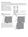
DIN-Rail Mounting
The aluminum DIN-rail attachment plate should already be fixed to the
back panel of the NPort S9450I when you take it out of the box. If you
need to reattach the DIN-rail attachment plate to the NPort S9450I, make
sure the stiff metal spring is situated towards the top as shown in the
figures below.
STEP 1: If the spring-loaded
bracket is locked in place,
push the recessed button to
release it. Once released, you
should feel some resistance
from the spring as you slide
the bracket up and down a few
millimeters in each direction.
STEP 2:
Insert the top of
the DIN rail
into the top slots on the
DIN-rail attachment plate.
STEP 3:
The DIN
-r
ail attachment unit will snap
into place as shown in the following
illustration.
To remove the Moxa NPort S9450I
switch from the DIN
rail, use a
screwdriver to push
down the
spring
-
loaded bracket until it locks
in place, as shown in the following
diagram. Next, rotate the bottom
of the switch upwards and then
remove the switch from the DIN
r
ail.

- 5 -
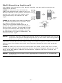
Wall-Mounting (optional)
For added convenience, the NPort S9450I can be wall-mounted as
illustrated below.
STEP 1: Remove the aluminum
DIN-rail attachment plate from the
NPort S9450I’s rear panel, and then
attach the wall-mount plates with
six M3 screws, as shown on the
right.
STEP 2: Mounting the NPort S9450I
to a wall requires four screws. Use
the NPort S9450I with the
wall-mount plates attached as a
guide to mark the correct locations
for the four screws. The heads of the
screws should be less than 6.0 mm
in diameter, and the shafts should
be less tha
n 3.5 mm in diameter, as
shown on the right.
NOTE
Test the screw’s head and shank size by inserting the screw into
one of the keyhole
-shaped apertures of the wall-
mounting plates
before you put the screws into the wall
DO NOT screw the screws all the way in—leave a space of about 2 mm to
allow room for sliding the wall-mount panel between the wall and the
screws.
STEP 3: After the screws are fixed into the wall, insert the four screw
heads through the large opening of the keyhole-shaped apertures, and
then slide the NPort S9450I downwards. Tighten the four screws for
added stability.
NOTE
Installed to the wall of an appropriate enclosure or industrial
machinery.

- 6 -
Rack-Mounting
Use four screws to attach the NPort S9650I Series to a standard rack.
Software Installation Information
For the NPort’s configuration, the default IP address of the NPort is
192.168.127.254. You may log in with the account name admin and
password moxa to change any settings to meet your network topology
(e.g., IP address) or serial device (e.g., serial parameters).
For software installation, download the relative utilities from Moxa's
website:
https://www.moxa.com/support/support_home.aspx?isSearchShow=1
• Download the NPort Windows Driver Manager and install it as the
driver to run with Real COM mode of the NPort Series.
• Execute NPort Windows Driver Manager; then map the virtual COM
ports on your Windows platform.
• You may refer to the DB9 Male pin assignment section to loop back
pin 2 and pin 3 for the RS-232 interface to carry out a self-test on the
device.
• Use HyperTerminal or a similar program (you may download Moxa's
program, called PComm Lite) to test whether the device is good or
not.
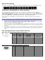
Pin Assignments and Cable Wiring
DB9 Male RS-232/422/485 Port Pinouts
Pin
RS-232
RS-422/485-4w
RS-485-2w
1
DCD
TxD-(A)
–
2
RxD
TxD+(B)
–
3
TxD
RxD+(B)
Data+(B)
4
DTR
RxD-(A)
Data-(A)
5
GND
GND
GND
6
DSR
–
–
7
RTS
–
–
8
CTS
–
–
9
–
–
–
DB9 Female RS-232/422/485 Port Pinouts
Pin
RS-232
RS-422/485-4w
RS-485-2w
1
DCD
TxD-
–
2
TxD
RxD+
Data+
3
RxD
TxD+
–
4
DSR/+IRIG-B
DSR/+IRIG-B
DSR/+IRIG-B
5
GND
GND
GND
6
DTR
–
–
7
CTS
RxD-
DATA-
8
RTS
–
–
9
–
–
–

- 7 -
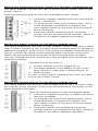
Wiring the Redundant Power Inputs for the NPort S9450I Series
The NPort S9450I unit has two sets of power inputs: power input 1 and
power input 2.
Take the following steps to wire the redundant power inputs:
1.
Insert the negative/positive DC wires into the N
-
and L+ terminals.
2.
To keep the DC wires from pulling loose, use a
small flat-blade screwdriver to tighten the
wire-clamp screws on the front of the terminal
block connector.
3.
Insert the plastic terminal block connector
prongs into the t
erminal block receptor, which is
located on the NPort S9450I’s top panel.
Wiring the Relay Contact for the NPort S9450I Series
The NPort S9450I has two sets of relay outputs: relay 1 and relay 2. Each
relay contact consists of two contacts of the terminal block on the NPort
S9450I’s top panel. Refer to the next section for detailed instructions on
how to connect the wires to the terminal block connector and how to
attach the terminal block connector to the terminal block receptor.
The two contacts used to connect the relay contacts work as follows (see
illustration below):
The fault circuit will open if
1.
A relay warning event is triggered, or
2.
The NPort S9450I is the Master of this Turbo
Ring, and the Turbo Ring is disconnected, or
3.
Start-up fails.
If none of these three conditions
are met, the fault
circuit will
remain closed.
Wiring the Digital Inputs for the NPort S9450I Series
The NPort S9450I unit has two sets of digital inputs: DI 1 and DI 2. Each
DI consists of two contacts of the 8-pin terminal block connector on the
NPort S9450I’s top panel.
Take the following steps to wire the digital inputs:
1.
Insert the negative (ground) or positive DI wires
into the terminals.
2.
To keep the DI wires from getting loose, use a
small flat-blade screwdriver to tighten the
wire-clamp screws on the front of the terminal
block connector.
3.
Insert the plastic terminal block connector
prongs into the terminal block receptor, which is
located on the NPort S9450I’s top panel.

- 8 -
ATTENTION
When wiring the relay contact (R), digital input (DI) and power
inputs (P1/P2), we suggest using the cable type
-
AWG (American
Wire Gauge) 18
-24(1.31-0.205 mm²
) and the corresponding pin
type
cable terminals. The rated temperature of wiring should be
at least 105°C.
We suggest using a torque value of 1.7lb
-
in; do not use excessive
force.
ATTENTION
Pl
ease use a power defined by SELV or one complying
with double
insulation under the UL 60950, UL 61010
-1, and UL 61010-2-
201
standard
, or from the circuit, which is isolated between the m
ains
by
reinforced or double insulation.
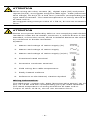
Symbol:
1. Nature and ratings of mains supply (dc)
2. Nature and ratings of mains supply
3. Nature and ratings of mains supply (ac/dc)
4. Functional earth terminal
5. Protective conductor terminal
6. Field wiring box cable temperature
7. Easily heated surfaces
8. Reference to the Manual, Caution Symbol
Wiring Information:
The cable type
—copper only. AWG (American Wire Gauge) 18-
12
Sol; 14
-12 Str and the corresponding pin type cable terminals.
The rated temperature of wiring should be at least 105°C.
Torque of value 12 lb-in; do not use excessive force.

- 9 -
ATTENTION
Veuillez utiliser une puissance définie par SELV ou une autre
conforme à la double isolation selon la norme UL 60950, UL
61010
-1 ou UL 61010-2-201, ou à partir du circuit qui est isolé
entre Mains by Reinforce ou Double isolation.
Symbole:
1. Terre de protection
2. Attention
Informations de câblage:
Le type de câble
- Cuivre seulement, AWG (American Wire
Gauge) 18
-12 Sol; 14-12 Str et les cosses de câble
correspondantes. La température nominale du câblage doit être
d'au moins 105 ° C.Couple de valeur 12 lb
-in; N'utilisez pas de
force excessive.
WARNING
LED or LASER components in compliance with IEC 60825
-1:
CLASS 1 LASER PRODUCT
CLASS 1 LED PRODUCT
Connecting the Power for the NPort S9650I Series
The NPort S9650I Series has two sets of power inputs: power input 1 and
power input 2.
STEP 1: Insert the dual set positive/negative DC wires into PWR1 and
PWR2 terminals (+ → pins 1, 9; - → pins 2, 10). Or insert the L/N AC
wires into PWR1 and PWR2 terminals (L → pin 1, 9; N → pin 2, 10)
STEP 2: To keep the DC or AC wires from pulling loose, use a screwdriver
to tighten the wire-clamp screws on the front of the terminal block
connector.
Wiring the Relay Contact for the NPort S9650I
Series
The NPort S9650I Series has one relay output. The relay contact of the
10-pin terminal block connector is used to detect user-configured events.
The two wires attached to the RELAY contacts form an open circuit when
a user-configured event is triggered. If a user-configured event does not
occur, the RELAY circuit will be closed.

- 10 -
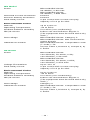
WV Model
Power
NPort S9450I Series:
24-48VDC, 0.6A max.
NPort S9650I Series:
24-48VDC, 1.68A max.
Overload Current Protection
Present
Reverse Polarity Protection
Present
Fault Relay Circuit
2-pin circuit with current-carrying
capacity of 2 A @ 30 VDC
Environmental Limits
Altitude
up to 2,000 m
Operating Temperature
-40 to 85°C
Ambient Relative Humidity
5 to 95% (non-condensing)
IEC/UL 61010
Indoor use and Pollution degree 2
(The equipment must be dried with a dry
cloth.)
Overvoltage
NPort S9450I Series: Category 2
NPort S9650I Series: Not connected to
mains directly
Hazardous Location
NPort S9450I Series: Temperature code
(T-Code)—T4
UL/cUL Class I, Division 2, Groups A, B,
C and D
HV Model
Power
NPort S9450I Series:
100
-220VAC, 50-60Hz, 0.2A;
100
-220VDC, 0.2A max.
NPort S9650I Series:
100
-240VAC, 50-60Hz, 0.65A;
100-250VDC, 0.47A max.
Voltage Fluctuations
Up to ±10 %
Fault Relay Circuit
2-pin circuit with current-carrying
capacity of 2 A @ 30 VDC
Environmental Limits
Altitude
Up to 2,000 m
Operating Temperature
-40 to 85°C
Ambient Relative Humidity
5 to 95% (non-condensing)
IEC/UL 61010
Indoor use and Pollution degree 2
(The equipment must be dried with a dry
cloth.)
Overvoltage
Category 2
Hazardous Location
NPort S9450I Series: Temperature code
(T-Code)—T4
UL/cUL Class I, Division 2, Groups A, B,
C and D

- 11 -
ATTENTION
This equipment is intended to be used in a Restricted Access
Location. If the equipment is used in a manner not specified by
the manufacturer, the protection provided by the equipment may
be impaired.
The product ambient temperature should
not exceed 85°C.
Cet équipement est destiné à être utilisé dans un lieu d'accès
restreint. Si l'équipement est utilisé d'une manière non spécifiée
par le fabricant, la protection fournie par l'équipement peut être
compromise.
La température ambiante du produit ne doit pas dépasser 85 ° C.
ATTENTION
For NPort S9450I Series:
These devices are open
-
type devices that are to be installed in an
enclosure that is suitable for the environment and where the
internal compartment
is only accessible by the use of a tool.
SUITABLE FOR USE IN CLASS I, DIVISION 2, GROUPS A, B, C
AND D HAZARDOUS LOCATIONS, OR NONHAZARDOUS
LOCATIONS ONLY.
WARNING
- EXPLOSION HAZARD - DO NOT DISCONNECT
EQUIPMENT INPUT TERMINAL BLOCK WHILE THE CIRCUIT IS
L
IVE OR UNLESS THE AREA IS KNOWN TO BE FREE OF
IGNITABLE CONCENTRATIONS.
-
 1
1
-
 2
2
-
 3
3
-
 4
4
-
 5
5
-
 6
6
-
 7
7
-
 8
8
-
 9
9
-
 10
10
-
 11
11


Moxa NPort S9650I Series Guide d'installation rapide
- Taper
- Guide d'installation rapide
- Ce manuel convient également à
dans d''autres langues
Documents connexes
Autres documents
-
Dedicated Micros EPOS Interface Unit Guide d'installation
-
Kathrein UFX 312 Manuel utilisateur
-
 KYLAND Technology KPS3102 Series Hardware Installation Manual
-
Weidmueller 2682600000 Guide d'installation
-
JBL GTO19T Manuel utilisateur
-
Asante Universal Serial Bus Hub USB Hub-4 Manuel utilisateur
-
Oracle StorageTek 8 Gb FC PCIe HBA Guide d'installation
-
SCS MONITOR Manuel utilisateur
-
Korenix JetPort 5801 Quick Installation Manual
-
red lion ST Manuel utilisateur
