Valor 2200 Le manuel du propriétaire
- Catégorie
- Cheminées
- Taper
- Le manuel du propriétaire
Ce manuel convient également à

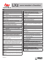
Installation Steps—Use both the 2200J engine and accessories installation manuals.
1. You need to know:
• height of the appliance and hearth, if used
• thickness and type of wall fi nish around the
appliance
• what accessories will be installed with this
fi replace (shelves, underbed lighting kit)
• venting confi guration - 4” x 6-5/8” or 5” x 8”
2. Carefully unpack the appliance and recycle the
packaging.
3. Remove the base plate and front window and set
them aside in a safe place to avoid damage.
4. Take out of the fi rebox any items which have been
packed inside for transportation.
5. Check that you have all the components in hand
for the installation. This includes:
• liner panels (in separate cartons)
• fuel bed (in separate cartons)
• remote battery and wall switch kit RBWSK
(required)
• LDK HeatShift Duct Kit - MANDATORY
INSTALLATION
• gas conversion kit if required
• venting components and accessories
• electrical components overhead decorative
lighting and optional underbed lighting
6. If the appliance needs gas conversion, convert
the appliance now with the optional kit listed in the
appliance manual. You will need to remove the
burner to proceed.
7. Look up framing dimensions, clearances to
projections requirements, HeatShift and venting
information in the installation manuals supplied
with the appliance and accessories to ensure
that the cavity is of appropriate dimensions.
8. Finish the framing.
9. Install the standoff s on the appliance as indicated
in the installation manual.
10. Install the 4” x 6-5/8” vent outlet adapter if
necessary.
11. Install the LDK HeatShift Duct Kit’s outlet collars.
12. Install the 2200ULK—Underbed Lighting Kit if
used.
13. Prepare the appliance for electrical connections—
overhead lighting and optional underbed lighting if
used.
4006569-02
LX2
2200 Installer’s Checklist
14. Prepare the appliance for RBWSK—Remote
Battery and Wall Switch Kit (required).
15. Roughly fi t the appliance into the framing
cavity, keeping the left side back of case still
accessible.
16. Connect and test the electrical wiring to the
fi replace.
17. Connect and test gas supply.
18. Install and test RBWSK—Remote Battery and
Wall Switch Kit (required).
19. Fit the appliance in fi nal position into framing.
20. Install the LDK HeatShift Duct Kit (required).
21. Install and connect the venting system according
to chosen confi guration and seal the vent pipes
joints.
22. Position the restrictors.
23. Install the liner panels in the fi rebox.
24. Install the fuel bed in the fi rebox.
25. Refi t the window, check spring-loaded window
return.
26. Check lighting and adjust the aeration settings if
necessary.
27. INSTRUCT THE CONSUMER ON HOW TO
OPERATE AND MAINTAIN THE FIREPLACE.
• show where the controls are (gas valve, gas
shut-off valve, wall switch, accessories) and
how to access them
• show how to operate the remote control and
the wall switch
• show how to turn the fi replace off in case of
emergency
28. Reinstall the Hot Glass Warning plate on the
bottom edge of the window if it has been removed.
29. Install the black base plate in front of the window.
30. Install the barrier screen to the fi replace.
31. Install the remote control handset wall holder as
required.
32. Finish the wall around the fi replace.
33. Leave all the instruction manuals and
documents, including this one, with the
consumer.

LE PREMIER
FOYER À GAZ RADIANT
MC
®
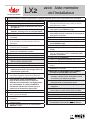
LX2
2200 Aide-mémoire
de l’installateur
Étapes d’installation—Utilisez conjointement les guides d’installation fournis avec le foyer 2200J et les accessoires.
1. Vous devez savoir :
• hauteur de l’appareil et de la dalle s’il y a lieu
• épaisseur et le type de fi nition du mur autour
de l’appareil
• quels accessoires seront utilisés avec le foyer
(tablettes, éclairage sous le lit d’alimentation)
• confi guration d’évacuation - 4” x 6-5/8” ou 5” x 8”
2. Déballez soigneusement l’appareil et recyclez
l’emballage.
3. Enlevez la base noire et la vitre avant et mettez-
les de côté dans un endroit sûr pour éviter les
dommages.
4. Enlevez de l’intérieur du foyer tous les articles qui y
ont été mis pour le transport.
5. Assurez-vous d’avoir en main tous les articles
requis pour l’installation, incluant :
• panneaux intérieurs (emballés séparément)
• lit d’alimentation (emballé séparément)
• porte-piles et interrupteur mural RBWSK (exigé)
• Système de canalisation LDK HeatShift -
INSTALLATION OBLIGATOIRE
• trousse de conversion de gaz si nécessaire
• accessoires de système d’évacuation
• accessoires électriques pour l’éclairage
d’ambiance du dessus et éclairage sous le lit
d’alimentation (optionnel)
6. Si le foyer requiert la conversion de gaz,
convertissez l’appareil maintenant à l’aide de la
trousse appropriée. Vous devrez enlever le brûleur.
7. Consultez les guides d’installation du
foyer et des accessoires pour vérifi er les
dimensions d’encastrement, les dégagements
aux combustibles, le système HeatShift et
d’évacuation afi n de vous assurer que le la
cavité sera de dimensions appropriées.
8. Finissez la structure d’encastrement.
9. Installez les écarteurs sur l’appareil tel qu’indiqué
dans le guide d’installation.
10. Installez l’adaptateur d’évent 4” x 6-5/8” si
nécessaire.
11. Installez les buses du système HeatShift sur
l’appareil (exigé).
12. Installez l’Éclairage sous le lit d’alimentation
2200ULK si utilisé.
13. Préparez l’appareil pour la connexion électrique—
éclairage d’ambiance du haut (inclus) et celui du
fond (optionnel) si utilisé.
14. Préparez l’appareil pour le Porte-piles et
interrupteur mural RBWSK (exigé).
15. Mettez l’appareil partiellement dans la cavité
d’encastrement tout en laissant un accès pour le
côté gauche à l’arrière.
16. Raccordez et vérifi ez l’alimentation électrique.
17. Raccordez et vérifi ez l’alimentation de gaz.
18. Installez et vérifi ez le Porte-piles et interrupteur
mural RBWSK (exigé).
19. Placez l’appareil en position fi nale.
20. Installez le Système de canalisation LDK HeatShift
(exigé).
21. Installez et raccordez le système d’évacuation
selon la confi guration choisie et scellez les joints
conduits d’évacuation.
22. Positionnez les restricteurs.
23. Installez les panneaux intérieurs dans le foyer.
24. Installez le lit d’alimentation dans le foyer.
25. Réinstallez la fenêtre et vérifi ez son mécanisme à
ressort.
26. Vérifi ez l’allumage et ajustez les réglages
d’aération si nécessaire.
27. MONTREZ AU CONSOMMATEUR COMMENT
UTILISER ET ENTRETENIR LE FOYER.
• montrez où sont les boutons commandes
(soupape, robinet d’arrêt, interrupteur mural,
accessoires) et comment y accéder
• montrez comment faire fonctionner la
télécommande et l’interrupteur mural
• montrez comment éteindre le foyer en cas
d’urgence
28. Installez le côté français de la plaquette de
sécurité dans le cadre extérieur de la fenêtre.
29. Installez la base noire devant la fenêtre.
30. Installez le pare-étincelles.
31. Installez le support mural de manette.
32. Finissez le mur autour du foyer.
33. Remettez au consommateur tous les guides
d’installation et documents, incluant celui-ci.
-
 1
1
-
 2
2


Valor 2200 Le manuel du propriétaire
- Catégorie
- Cheminées
- Taper
- Le manuel du propriétaire
- Ce manuel convient également à
dans d''autres langues
- English: Valor 2200 Owner's manual
Documents connexes
-
Valor 2100PKN/PKP Guide d'installation
-
-
-
-
-
-
-
-
-