QSC PL-3.4 Manuel utilisateur
- Catégorie
- Matériel musical
- Taper
- Manuel utilisateur

1
Turn-on/turn-off muting .................................... 19
Mise en sourdine lors de la mise sous/hors tension
Stummschaltung bei An-und Ausschalten
Enmudecimiento de encendido/apagado
Short circuit protection .................................. 19
Protection contre les court-circuits
Schutz bei Kurzschluß
Protección contra corto-circuito
Clip limiting ........................................................ 19
Limiteur d'écrêtement
Übersteuerungsbegrenzung
Limitando clips
Thermal protection .......................................... 20
Protection thermique
Thermische Schutzschaltung
Protección térmica
DC fault protection .......................................... 20
Protection contre une anomalie CC
Schutz gegen Gleichspannung
Protección contra corriente continua
Input/output protection ................................... 20
Protection entrées/sorties
Eingangs-/Ausgangsschutz
Protección entrada/salida
SPECIFICATIONS ............................................... 21
SPÉCIFICATIONS
TECHNISCHE DATEN
ESPECIFICACIONES
WARRANTY INFORMATION ............................ 23
INFORMATIONS DE GARANTIE
GARANTIEBEDINGUNGEN
INFORMACIÓN DE GARANTÍA
ADDRESS &
TELEPHONE INFORMATION ................... 24
ADRESSE POSTALE ET NUMÉROS
ANSCHRIFT UND TELEFONNUMMERN
DIRECCIÓN Y TELÉFONO
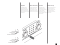
Explanation of graphical symbols ................... 2
Explication des symbole graphiques
Erklärung der bildsymbole
Explicación de símbolos
FCC Statement ..................................................... 3
Déclaration de FCC
FCC-Erklärung
Declaración de FCC
INTRODUCTION ................................................... 5
AVANT-PROPOS
EINFÜHRUNG
INTRODUCCIÓN
Front panel ........................................................... 6
Panneau avant
Vorderseite
Panel frontal
Rear panel............................................................ 7
Panneau arrière
Rückseite
Panel posterior
MOUNTING .................................................................... 8
MONTAGE
BEFESTIGUNG
MONTAJE
Front ...................................................................... 8
Avant
Vorn
Frente
Rear ....................................................................... 9
Arrière
Hinten
Trasera
Operating voltage (AC mains) ....................... 10
Tension d’utilisation (alimentation CA)
Netz-Betriebspannung
Voltaje de funcionamiento (CA)
Inputs .................................................................. 10
Entrées
Eingänge
Entradas
Outputs ................................................................ 11
Sorties
Ausgänge
Salidas
DataPort .............................................................. 11
Port de Données
DataPort
Puerto de Datos
OPERATION ........................................................ 12
FONCTIONNEMENT
BETRIEB
OPERACIÓN
Gain controls ..................................................... 12
Commandes de gain
Pegelsteller
Controles de ganancia
Remote power supply control ....................... 12
Télécommande du bloc d’alimentation
Ferneinschaltung
Control remoto de alimentación
Clip limiter .......................................................... 13
Limiteur d'écrêtement
Clip-Limiter
Limitador anti-clip
LED indicators ................................................... 14
Indicateurs DEL
LED-Anzeigen
Indicadores LED
Parallel, stereo, and bridged mono ............. 15
Modes parallèle, stéreo, et mono ponté (bridgé)
Stereobetrieb, Eingangsparallelschaltung,
und Mono-Brückenbetrieb
Paralelo, estéreo, y mono puente
Using the PowerLight 3.8
X
.....................................................
17
Utilisation du PowerLight 3.8
X
Benutzung des PowerLight 3.8
X
Uso del PowerLight 3.8
X
PROTECTION ...................................................... 19
PROTECTION
SCHUTZSCHALTUNGEN
PROTECCIÓN
TABLE OF CONTENTS
-
TABLE DES MATIÈRES
-
INHALTSVERZEICHNIS
-
TABLA DE LAS MATERIAS

2
Erklärung der
Bildsymbole
Das Blitzzeichen innerhalb eines
gleichseitigen Dreiecks warnt den
Benutzer vor nicht-isolierter,
gefährlicher Spannung im Inneren
des Gerätes. Diese Spannung ist
hoch genug, um Personen durch
elektrischen Schlag zu gefährden.
Das Ausrufungszeichen innerhalb
eines gleichseitigen Dreiecks weist
den Benutzer auf wichtige
Bedienungs- und
Wartungsanweisungen hin, die in
den gerätebegleitenden Unterlagen
aufgeführt sind.
Explicación de
símbolos
El rayo inscrito en un triángulo
equilátero alerta al usuario de la
presencia de voltaje peligroso no
aislado dentro del producto, que
pude ser de nivel suficiente como
para constitutuir riesgo de descarga
eléctrico para las personas.
El signo de exclamación inscrito en
un triángulo equilátero alerta a los
usuarios de la presencia de
instrucciones importantes de
funcionamiento y mantenimiento
(servicio) en la literatura que
acompaña al producto.
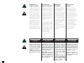
Explanation of
graphical symbols
The lightning flash with arrowhead
symbol, within an equilateral
triangle, is intended to alert the user
to the presence of uninsulated
“dangerous voltage” within the
product’s enclosure that may be of
sufficient magnitude to constitute a
risk of electric shock to humans.
The exclamation point within an
equilateral triangle is intended to
alert the users to the presence of
important operating and mainte-
nance (servicing) instructions in the
literature accompanying the product.
Explication des
symboles graphiques
Le symbole éclair avec pointe de
flèche à l'intérieur d'un triangle
équilatéral est utilisé pour alerter
l'utilisateur de la présence à
l'intérieur du coffret de "tension non-
isolée dangereuse" d'ampleur
suffisante pour constituer un risque
de choc électrique pour l'être
humain.
Le point d'exclamation à l'intérieur
d'un triangle équilatéral est employé
pour alerter les utilisateur de la
présence d'instructions importantes
pour le fonctionnement et l'entretien
(service) dans les documents
accompagnant l'appareil.
CAUTION: To reduce the risk of
electric shock, do not remove
the cover. No user-serviceable
parts inside. Refer servicing to
qualified service personnel.
WARNING: To prevent fire or
electric shock, do not expose
this equipment to rain or mois-
ture.
ATTENTION: Pour éviter les
risques de choc électrique, ne
pas enlever le couvercle. Cet
appareil ne comporte aucune
pièce pouvant être réparée par
l'utilisateur. Confier l'entretien
à un technicien qualifié.
AVERTISSEMENT: Pour éviter le
risque de choc électrique ou
d'incendie, n'exposez cet
appareil ni à l'humidité exces-
sive ni aux projections d'eau
(pluie, ruissellement, etc …)
VORSICHT: Um Gefährdung
durch elektrischen Schlag zu
vermeiden, darf das Gehäuse
nicht geöffnet werden. Es
befinden sich keine vom
Benutzer reparierbaren Teile
im Inneren des Gerätes.
Überlassen Sie jegliche
Raparatur dem qualifizierten
Fachmann.
WARNUNG: Um die Gefahr eines
Brandes bzw. eine Verletzung
durch elektrischen Schlag zu
vermeiden, sollten Sie das Gerät
niemals Regen oder
Feuchtigkeit aussetzen.
PRECAUCIÓN: Para reducir el
riesgo de descarga eléctrica,
no quite la tapa. No hay en el
interior nada para ajustar por
el usuario. Refiera sus
reparaciones a personal
cualificado de servicio.
AVISO: Para impedir fuegos o
descargas eléctricas, no
exponga este equipo a la lluvia
o la humedad.
CAUTION
RISK OF ELECTRIC SHOCK
DO NOT OPEN
ATTENTION!
RISQUE DE CHOC ÉLECTRIQUE
NE PAS OUVRIR
VORSICHT
GEFAHR EINES ELEKTRISCHEN
SCHLAGES. NICHT ÖFFNEN!
PRECAUCIÓN
RIESGO DE DESCARGA
ELÉCTRICA. NO LO ABRA.
La page charge ...
La page charge ...
La page charge ...

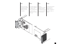
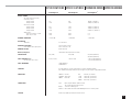
6
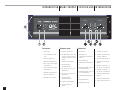
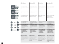
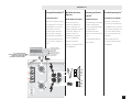
1. Power switch
2. Protect, Standby, and Power
LEDs
3. Gain control (Channel 1)
4. Clip limiter switch (Channel 1)
5. Clip, -10 dB, -20 dB and Signal
LEDs (Channel 1)
6. Clip, -10 dB, -20 dB and Signal
LEDs (Channel 2)
7. Clip limiter switch (Channel 2)
8. Gain control (Channel 2)
9. Mounting holes for handles
Panel frontalPanneau avant
ON
OFF
4000W PROFESSIONAL AMPLIFIER
POWERLIGHT 4.0
PROTECT
STANDBY
POWER
24
28
38
30
32
34
36
-¥
26
24
20
14
dB
CHANNEL 1
24
28
38
30
32
34
36
-¥
26
24
20
14
dB
CHANNEL 2
CLIP
-10dB
-20dB
SIGNAL
CLIP LIMITER
4 7
1 2 3 5 6 8
9
Vorderseite
INTRODUCTION
EINFÜHRUNG
INTRODUCCIÓN
AVANT-PROPOS
Front panel
1. Commande marche/arrêt
2. DELs (Diode ElectroLuminescente)
de modes Protect (protection),
Standby (en attente), et Power (en
fonction)
3. Commande de gain (Canal 1)
4. Sélecteur de limiteur
d'écrêtement (Canal 1)
5. DELs de Clip, -10 dB, -20 dB, et
Signal (Canal 1)
6. DELs de Clip, -10 dB, -20 dB, et
Signal (Canal 2)
7. Sélecteur de limiteur
d'écrêtement (Canal 2)
8. Commande de gain (Canal 2)
9. Trous de montage pour
poignées
1. Netzschalter
2. LED-Anzeige für
Schutzschaltung, Standby und
Betrieb
3. Pegelsteller (Kanal 1)
4. Schalter für Clip-Limiter (Kanal
1)
5. LED-Anzeige für Clip, -10 dB, -20
dB und Signal (Kanal 1)
6. LED-Anzeige für Clip, -10 dB, -20
dB und Signal (Kanal 2)
7. Schalter für Clip-Limiter (Kanal
2)
8. Pegelsteller (Kanal 2)
9. Griffbefestigungslöcher
1. Interruptor de encendido
2. Indicadores LED de Protección,
“Standby” y Operación
3. Control de ganancia (Canal 1)
4. Conmutador de limitador-clip
(Canal 1)
5. Indicadores LED de “Clip,” -10
dB, -20 dB y “Signal” (Canal 1)
6. Indicadores LED de “Clip,” -10
dB, -20 dB y “Signal” (Canal 2)
7. Conmutador de limitador-clip
(Canal 2)
8. Control de ganancia (Canal 2)
9. Agujeros para montaje de asas

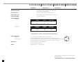
7
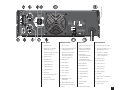
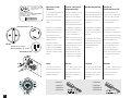
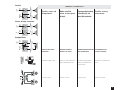
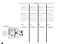
Rear panel
1. Input barrier strip
2. Data Port (for use with QSC
MultiSignal Processor)
3. Parallel/Stereo/Bridge switch
(except PowerLight 3.8
X
)
4. Input (Channel 1)
5. Input (Channel 2)
6. + Output (Channel 1)
7. + Output (Channel 2)
8. - Output (Channel 1)
9. - Output (Channel 2)
10. Cooling fan
11. Remote power supply control
12. AC mains cable
13. Rear chassis support tab
Panneau arrière
1. Bornier d’entrée
2.
Port de Données (pour utilisation avec
les QSC MultiSignal Processor)
3. Sélecteur de mode Parallel/
Stereo/Bridge (Parallèle/
Stéréo/Ponté)
(excepté le
modèle PowerLight 3.8
X
)
4. Entrée (Canal 1)
5. Entrée (Canal 2)
6. Sortie + (Canal 1)
7. Sortie + (Canal 2)
8. Sortie - (Canal 1)
9. Sortie - (Canal 2)
10. Ventilateur
11. Télécommande du bloc
d’alimentation.
12. Câble d’alimentation secteur
13. Patte de support de l’arrière du
châssis
Rückseite
1. Eingangs-Schraubanschlüsse
2. Data Port (Zum Gebrauch in
Verbindung mit dem QSC
MultiSignal-Prozessor)
3. Umschalter für
Eingangsparallelschaltung,
Stereobetrieb, Mono-
Brückenschaltung
(außer
Verstärkertyp PowerLight 3.8
X
)
4. Eingang (Kanal 1)
5. Eingang (Kanal 2)
6. + Ausgang (Kanal 1)
7. + Ausgang (Kanal 2)
8. - Ausgang (Kanal 1)
9. - Ausgang (Kanal 2)
10. Lüfter
11. Ferneinschaltung
12. Netzkabel
13. Hintere Rackbefestigung
Panel posterior
1. Tira de terminales de entrada
2. Puerto de datos (para uso con el
QSC MultiSignal Processor)
3. Conmutador de Paralelo/
Estéreo/Puente
(excepto el
modelo PowerLight 3.8
X
)
4. Entrada (Canal 1)
5. Entrada (Canal 2)
6. Salida + (Canal 1)
7. Salida + (Canal 2)
8. Salida - (Canal 1)
9. Salida - (Canal 2)
10. Ventilador
11. Control remoto de alimentación
12. Cable de red
13. Lengüeta de soporte de la
trasera del chasis
STANDBY
POWER SUPPLY
CONTROL
TM
INPUT IMPEDANCE
20K BALANCED
10 K UN B AL A N CED
INPUT SENSITIVITY
POWERLIGH T 1.0=1.01V
POWERLIGHT 1.4=1.00V
POWERLIGHT 1.8=1.16V
POWERLIGHT 3.4=0.99V
POWERLIGHT 4.0=1.08V
CLIP LIMITER:
RECESSED PUSH
SWITC H E S ARE LO CATED
ON THE FRO NT PA NEL.
CLIP LI M OF F
CLIP LIM ON
CERT I FIED T O C O MPLY WITH C LA SS B
LIMI TS PART 15 O F FC C RULES
SEE IN STRUCTI ONS IF IN TE RF ERENC E
TO RA DI O RECEPT I O N IS SUS PE CT ED
ENABLE
INPUT
INPUT
STEREO
PARALLEL BRIDGE
CH 1
CH 2
SLV
RING
TIP
P2 P1
P3
SLV
RING
P2 P1
P3
D
A
T
A
P
O
R
T
OUTPUT
OUTPUT
BRIDGED
MONO
CH 1
CH 2
11 12932
5
7
10
8
64
1
13
QSC AUDIO PRODUCTS, LLC

8
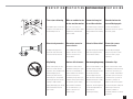
MONTAGE BEFESTIGUNG MONTAJEMOUNTING
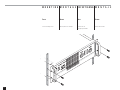
Front
Use four mounting screws.
Avant
Utiliser quatre vis de montage.
Vorn
Benutzen Sie vier
Befestigungsschrauben.
Frente
Utilice cuatro tornillos.

9
Rear
Rear rack ears are optional but
recommended. Kits are available
from QSC’s Technical Services
Department or from your local
dealer/distributor.
Arrière
Bien que facultatif, l’installation d’un
support à l’arrière de l’amplificateur
est recommandé. Un jeu de
plaquettes est disponible à cet effet
au département des services
techniques ou chez votre marchand/
distributeur local.
Hinten
Rückseitige 19"-
Befestigungslaschen sind nicht im
Lieferumfang, können aber von
Ihrem Fachhändler bezogen werden.
Diese werden an den vorhandenen
Gehäuselaschen befestigt.
Trasera
Las orejas traseras para montaje en
rack son opcionales, pero se
recomiendan. Existen “kits”
disponibles de el departamento de
servicios técnicos de QSC o de su
distribuidor.

10
Operating voltage
(AC mains)
The serial number label indicates the
correct AC mains voltage.
Connecting to the wrong voltage is
dangerous and may damage the
amplifier.
Tension d’utilisation
(alimentation CA)
L’étiquette sur laquelle est inscrit le
numéro de série de l’appareil
indique la tension CA appropriée.
Raccorder à une source de tension
inappropriée est dangereux et
pourrait endommager l’amplificateur.
Netz-Betriebspannung
Das Seriennummernetikett zeigt die
korrekte zulässige Betriebsspannung
an. Eine andere Netzspannung kann
den Verstärker beschädigen und
gefährlich sein.
Voltaje de
funcionamiento (CA)
En la etiqueta donde figura el
número de serie se indica el voltaje
correcto. La conexión a un voltaje
equivocado es peligrosa y puede
dañar el amplificador.
• Unbalanced
• Asymétrique
• Unsymmetrisch
• No balanceado
• Balanced
• Symétrique
• Symmetrisch
• Balanceado
QSC Audio Products
Costa Mesa, CA USA
Made in USA
Model: PWRLIGHT 4.0
Output Pwr. Per CH/IMP: 2000W/2 Ohms
230 VAC, 11 Amps, 50/60 Hz.
Serial 039703467
039703467
0
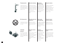
Inputs
The “combo” input connectors
accept standard male XLR and 6.3
mm (¼") TRS connectors, both
balanced and unbalanced.
Entrées
Les connecteurs d’entrée “combo”
acceptent les connecteurs XLR
mâles et TRS 6.3 mm (¼"), que le
branchement soit symétrique ou
asymétrique.
Eingänge
Die „Combo”- Eingangsbuchse kann
für XLR- und 6,3 mm Klinkenstecker
benutzt werden, und zwar sowohl
für unsymmetrische, als auch für
symmetrische.
Entradas
Los conectores “combo” de entrada
aceptan tanto XLR machos como
jacks de 6.3 mm (¼"), tanto
balanceados como no.
PowerLight 3.8
X
and 4.0 amplifiers
configured for 120-volt operation
are fitted with a twist-lock 30-
ampere power connector and
require an appropriate 30-ampere
AC circuit and outlet.
PowerLight 3.4 amplifiers
configured for 120-volt operation
are fitted with a standard NEMA
power connector and can operate
safely from a standard 15-ampere
AC circuit.
Les amplificateurs PowerLight 3.8
X
and 4.0 montés pour alimentation
120 volts sont équipés d'un
connecteur d'alimentation 30
ampères et nécessitent un prise de
courant de 30 ampères appriopriée.
Les amplificateurs PowerLight 3.4
montés pour alimentation 120 volts
sont équipés d'un connecteur
d'alimentation standard NEMA et
peuvent fonctionner sans risque
lorsque branchés sur une prise de
courant standard de 15 ampères.
120-V Gerätetypen der PowerLight 3.8
X
und 4.0 haben ein 30A Netzkabel
und Stecker. Sie brauchen einen 30A
Netzanschluß.
120V-Gerätetypen der PowerLight
3.4 haben ein Kabel mit einem 15A
NEMA-Netzstecker. Dieser Typ kann
mit Standard-Netzanschluß
betrieben werden.
Los amplificadores PowerLight 3.8
X
y
4.0 configurados para un
funcionamiento con 120 voltios tienen
un conector de potencia de 30 amperes
y requieren de una toma de corriente
alterna (CA) también de 30.
Los PowerLight 3.4 configuarados
para un funcionamiento con 120
voltios tienen un conector de
potencia tipo NEMA estándar y
pueden operar sin peligro conectado
a una toma de corriente alterna de
15 amps.
220–240V
PowerLight 4.0 & 3.8
X
: 120V
PowerLight 3.4: 120V
Outlets/Prises de courant/
Netzanschluß/Tomas de corriente

11
Sorties Ausgänge Salidas
Only non-European models accept
banana plugs.
Outputs
Insérer le fil de façon à ce qu'aucune
partie du conducteur ne soit
exposée; serrer le corps du
connecteur (utiliser une pièce de
monnaie si nécessaire).
Insert wire fully; tighten barrel (use
coin if necessary).
Prises banane avec modèles non-
européens seulement.
Das abisolierte Kabelende komplett
einführen, ohne daß blanker Draht
sichtbar bleibt; Klemme festdrehen.
Münze benutzen, falls notwendig.
Bananenstecker nur bei
außereuropäischen Gerätetypen
benutzen!
Inserte el cable hasta que nungún
conductor está expuesto; apriete la
rosca con fuerza, usando una
moneda si es necesario.
Conectores tipo plátano con
modelos no europeos solamente.
DataPort
For use with QSC MultiSignal
Processor or Basis processor. Use a
standard VGA cable for interconnec-
tion.
Port de Données
Pour utilisation avec les MultiSignal
Processors ou Processors Basis QSC;
utiliser un câble standard VGA pour
l'interconnexion.
DataPort
Zum Gebrauch in Verbindung mit
dem QSC MultiSignal-Prozessor
oder Basis Prozessor. Zur
Verbindung wird ein Standard-VGA-
Kabel benutzt.
Puerto de Datos
Para uso con el MultiSignal
Processor o procesor Basis de QSC.
Utiliza un cable VGA estándar para
interconectar.
Inputs (contined)
You can also connect the input wires
directly to the barrier strip as
shown.
Entrées (suite)
Vous pouvez aussi raccorder
directement les fils d’entrée aux
bornes tel qu’indiqué.
Eingänge (gleichmäßig)
Sie können aber auch—wie
gezeigt—die Eingangskabel direkt
auf die Klemmen schrauben.
Entradas (continuación)
También puede conectar cables
directamente a la tira de terminales
de entrada.
WARNING: To prevent electric
shock, do not operate the am-
plifier with any of the conductor
portion of the speaker wire ex-
posed.
¡AVISO! Para evitar una
descarga eléctrica, no opere el
amplificador si algún del cable
de la bocina está expuesto.
AVERTISSEMENT: Afin de
prévenir tout risque de choc
électrique, ne pas utiliser
l'amplificateur si une portion du
conducteur du fil de haut-
parleur est exposée.
WARNUNG: Um elektrische
Schläge zu vermeiden, sollte der
Verstärker nicht betrieben
werden, wenn blanke Kabel-
enden sichtbar sind.
0.25"
6.3 mm
≤
12.9 mm
0.51"
½"
13 mm
Strip back insulation 13 mm. Dénuder le fil sur un maximum de 13
mm (½ puce).
Das Kabelende nich länger als max.
13 mm abisolieren.
Remueva el aislamiento no más de
13 mm (½ pulgada).

12
OPERATION FONCTIONNEMENT BETRIEB
STANDBY
STANDBY
ENABLE
ENABLE
POWER SUPPLY
CONTROL
POWER SUPPLY
CONTROL
POWER SUPPLY
CONTROL
POWER SUPPLY
CONTROL
• One amplifier
• Un amplificateur
• Ein Verstärker
• Un amplificador
• Multiple amplifiers
• Multiples
amplificateurs
• Mehrere Verstärker
• Multi amplificadores
Standby
En attente
Standby
En attente
Operate
Marche
Betrieb
Marcha
Operate
Marche
Betrieb
Marcha
OPERACIÓN
Remote power supply
control
Télécommande du bloc
d’alimentation
Ferneinschaltung Control remoto de
alimentación
Gain controls
The numbers indicate actual voltage
gain of amplifier, in dB.
Commandes de gain
Les numéros indiquent le gain de
tension véritable de l’amplificateur,
en dB.
Pegelsteller
Die Ziffern zeigen die reale
Spannungsverstärkung des
Verstärkers in dB.
Controles de ganancia
Los números indican la ganancia de
voltaje del amplificador, en dB.
4000W PROFESSIONAL AMPLIFIER
2428
38
30
32
34
36
-∞
26
24
20
14
dB
CHANNEL 1
2428
38
30
32
34
36
-∞
26
24
20
14
dB
CHANNEL 2
CLIP
-10dB
-20dB
SIGNAL
CLIP LIMITER

13
Clip limiter
The clip limiter will prevent
continuous clipping in either
amplifier channel output. Below
clipping, and during short clips on
peaks, the clip limiter does not act on
the audio signal.
Limiteur d'écrêtement
Le limiteur d'écrêtement prévient
l'écrêtement continuel. Sous le
niveau d'écrêtement, et pendant
l'écrêtement transitoire, le limiteur
n'aura pas d'effet sur le signal audio.
Clip-Limiter
Der Clip-Limiter verhindert
dauerhafter Übersteuerung in
beiden Verstärkerausgangskanälen.
Auf Signale unterhalb der
Übersteuerunggrenze und bei
extrem kurzen Signalspitzen reagiert
der Clip-Limiter nicht.
Limitador anti-clip
El limitador anti-clip evita el clip de la
etapa de forma continuada. Por
debajo de la sefial de clip y durante
breves clips debidos a picos de
señal, el limitador no actuará sobre
la señal de audio.
CLIP
-10dB
-20dB
SIGNAL
CLIP LIMITER
24
34
26
28
30
32
-∞
-∞
22
20
16
10
dB
CHANNEL 2
24
34
26
28
30
32
-∞
22
20
16
10
dB
CHANNEL 1
-
∞-∞
10
Limiter off
Limiteur détaché
Limiter aus
Limitador desconectado
-
∞-∞
10
Limiter on
Limiteur attaché
Limiter ein
Limitador conectado

14
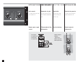
LED indicators
The red “PROTECT” LED glows
when the amplifier goes into protect
mode.
Indicateurs DEL
La DEL rouge “PROTECT” s’allume
quand l’amplificateur passe en mode
protection.
LED-Anzeigen
Aktivierung der Schutzschaltungen
wird durch die rote „PROTECT”- LED
angezeigt.
Indicadores LED
El indicador LED rojo de “PROTECT”
se enciende cuando se activan las
protecciones.
• This red LED lights when
the channel clips.
• Este indicador LED rojo se
enciende cuando el canal
está recortando.
• Cette DEL rouge s’allume
pour indiquer l’écrêtement
du signal.
• Diese rote LED leuchtet bei
Übersteuerung.
The yellow “STANDBY” LED lights
only when the amplifier is in standby
mode.
La DEL jaune “STANDBY” ne
s’allume que lorsque l’amplificateur
est en mode attente.
Die gelbe „STANDBY”-LED leuchtet
nur im Standby-Betrieb.
El indicador LED amarillo de
“STANDBY” se enciende cuando el
amplificador está en modo
“standby.”
The green “POWER” LED indicates
that the amplifier is operating.
La DEL verte “POWER” indique que
l’amplificateur est sous tension.
Die grüne „POWER”-LED ist die
Betriebsanzeige.
El indicador LED verde de “POWER”
se enciende cuando se el
amplificador está funcionando.
• These yellow LEDs light at
10 and 20 dB below the
channel’s maximum rated
output power.
• Ces DELs jaunes s’allument
à 10 et 20 dB sous le niveau
de puissance maximale du
canal.
• Diese gelben LED’s
leuchten bei 10 und 20 dB
unterhalb der maximalen
Ausgangsleistung.
• Este indicadores LED
amarillo se encienden a 10 y
20 dB por debajo de la
potencia máxima de los
canales.
• This green LED lights at
about 30 dB below
maximum rated output
power.
• Cette DEL verte s’allume à 30
dB sous le niveau de
puissance maximale du
canal.
• Diese grüne LED leuchtet
bei etwa 30 dB unterhalb
der maximalen
Ausgangsleistung.
• Este indicador LED verde se
enciende a 30 dB por
debajo de la potencia
máxima de los canales.
NOTE: Brief, occasional
clipping may be inaudible; this
is normal and acceptable. If
the red "CLIP" LED glows often
and continuously, reduce the
signal level.
NOTE: Il se peut que
d'écrêtement occasionel est
inaudible; ça c'est normal et
acceptable. Si la DEL “CLIP”
allume souvent ou sans
interruption, réduire le niveau
de signal.
ANMERKUNG: Gelegentliche
Übersteuerung ist oft
unhörbar; das ist normal und
akzeptabel. Falls die „CLIP“-
LED oft aufleuchtet oder sogar
dauerhaft, bitte den Pegel
zurücknehmen.
NOTA: Es posible y aceptable
que recorte brevemente en
ocasiones es inaudible. Si el
indicador LED de recorte
(“CLIP”) se enciende con
frecuencia y de forma
continuada, reduzca el nivel
de señal.

15
Parallel, stereo, and
bridged mono
Modes parallèle,
stéreo, et mono ponté
(bridgé)
Eingangsparallelschaltung,
Stereobetrieb, und
Mono-Brückenbetrieb
Paralelo, estéreo y
mono puente
Bridged Mono
Parallel
Stereo, bi-amp, 2-channel
Ch. 1
input
Ch. 2
input
Ch. 1
input
Ch. 2
input
Ch. 1
input
Ch. 2
input
Ch. 1
Ch. 1
Ch. 2
Ch. 2
Ch. 1
Ch. 1
Ch. 2
Ch. 2
Ch. 1
Ch. 1
Ch. 2
Ch. 2
2Ω
2Ω
2Ω
2Ω
16
8
4
Ω
Ω
Ω
16
8
4
Ω
Ω
Ω
PARALLEL AND STEREO
OPERATION
OPÉRATION EN MODES
PARALLÈLE ET STÉREO
FUNCIONAMIENTO EN
ESTÉREO Y PARALELO
Parallel/Stereo/Bridge switch Sélecteur de mode Parallel/Stereo/
Bridge (Parallèle/Stéréo/Ponté)
Conmutador de Paralelo/Estéreo/
Puente
Connecting outputs Connexion des sorties Conexión de las salidas
POWERLIGHT 3.4 & POWERLIGHT 4.0
EINGANGSPARALLELSCHALTUNG
UND STEREOBETRIEB
Umschalter für Eingangsparallel-
schaltung, Stereobetrieb, Mono-
Brückenschaltung
Ausgangsanschluß

16
4000W PROFESSIONAL AMPLIFIER
2428
38
30
32
34
36
-∞
26
24
20
14
dB
CHANNEL 1
2428
38
30
32
34
36
-∞
26
24
20
14
dB
CHANNEL 2
CLIP
-10dB
-20dB
SIGNAL
CLIP LIMITER
32
16
8
Ω
Ω
Ω
4Ω
4Ω
16
8
4
Ω
Ω
Ω
2Ω
2Ω
BRIDGED MONO OPERATION
BRIDGED-MONO MODE
CAUTION:
Output voltages higher than
100 volts rms are available
between the amplifier's
bridged terminals. CLASS 1
wiring methods, as specified
in accordance with national
and local codes, must be used
to connect the amplifier to the
load, and the load itself must
have a sufficient power rating
for use with the amplifier.
MONO-BRÜCKENBETRIEB
VORSICHT BEI MONO-
BRÜCKENBETRIEB:
Im Brückenbetrieb kann bei
den Verstärkeranschlußklemmen
eine Spannung von höher als
100 V anliegen. Entsprechend
sichere, isolierte Leitung muss
daher verwendet werden
(Bitte entsprechende
Länderrichtlinien und CE-
Bedingungen beachten!).
Auch muss die Anschlußlast
der Leistung der Verstärker
genügen.
FUNCIONAMIENTO EN MONO
PUENTE
PRECAUCIÓN PARA EL MODO
MONO PUENTE
Se pueden alcanzar voltajes
de más de 100 voltios rms con
las terminales de puente de
los amplificadores. Se deben
usar métodos de conexión
tipo CLASS 1 entre el
amplificador y la carga, tal y
como se especifica en los
códigos nacionales y locales.
La carga deberá contar con
suficiente potencia para ser
usada con el amplificador.
OPÉRATION EN MODE MONO
MODE BRIDGÉ MONO:
ATTENTION
Des tensions de sorties de
plus de 100 volts rms sont
disponibles entre les bornes
de l'amplificateur en mode
ponté. Utiliser les méthodes de
câblage de Classe 1, selon les
codes nationaux et locaux,
pour connecter
l'amplificateur à sa charge. La
charge doit être de capacité
de puissance suffisante pour
utilisation avec
l'amplificateur.
Connecting outputs Connexion des sorties Ausgangsanschluß Conexión de las salidas
Channel 2's gain control has no
effect in this mode.
Der Pegelsteller von Kanal 2 ist in
diesen Betriebsart deaktiviert.
Le contrôle de gain du canal 2 est
hors circuit dans ce mode.
La ganancia del canal 2 no tiene
ningún efecto en este modo.
Use Channel 1 to set gain. The gain
in bridged mono mode is 6 dB higher
than in stereo or parallel modes.
Utiliser le canal 1 pour ajuster le gain.
Le gain en mode bridgé mono est 6 dB
plus haut qu’en modes stéréo ou
parallèle.
Nur der Pegelsteller von Kanal 1 wird
zur Lautstärkeeinstellung benutzt. Im
Brückenbetrieb ist die Verstärkung 6 dB
höher als Stereo- oder Parallelbetrieb.
Utilice el control del canal 1 para
ajustar la ganancia. La ganancia en el
modo mono puente es 6 dB más fuerte
que en modos estéreos o paralelos.
POWERLIGHT 3.4 & POWERLIGHT 4.0

17
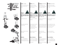
Using the PowerLight 3.8
X
CONNECTING INPUTS
This model is designed for use with
an external active crossover for bi-
amp applications, as shown here.
Connect the crossover's low-
frequency output to the input of
Channel 1, which is the higher-
powered channel of the amplifier.
Connect the high-frequency output
of the crossover to the Channel 2
input.
POWERLIGHT 3.8
X
Uso del PowerLight 3.8
X
CONEXIÓN DE LAS ENTRADAS
Este modelo se diseño para ser
usado con un crossover activo para
uso biamplificado, como se muestra
aquí. Conecte la salida de bajos del
crossover a la entrada del canal 1,
que es el canal de alto poder del
amplificador.
Conecte la salida de altos del
crossover a la entrada del canal 2
del amplificador.
Benutzung des Power-
Light 3.8
X
EINGANGSANSCHLÜßE
Dieser Verstärkertyp ist als Bi-Amp-
Verstärker zur Benutzung mit
externen Frequenzweichen gedacht.
Den Tieftonausgang der
Frequenzweiche mit Kanal 1
verbinden, der die höhere Leistung
besitzt.
Den Hochtonausgang daher mit
Kanal 2 verbinden.
CH1
/LF
CH2
/HF
INPUT
CH1/LF
OUTPUT
OUTPUT
CH2/HF
P1
P2
P3
SLV
RING
TIP
P
O
R
T
P
O
R
T
D
A
T
A
D
A
T
A
1
5
6
1
0
10
1
1
11
1
5
15
P1
P2
P3
SLV
RING
TIP
BRIDGED
MONO
CH1
/LF
CH2
/HF
INPUT
CH1/LF
OUTPUT
OUTPUT
CH2/HF
P1
P2
P3
SLV
RING
TIP
P
O
R
T
P
O
R
T
D
A
T
A
D
A
T
A
1
5
6
1
0
10
1
1
11
1
5
15
P1
P2
P3
SLV
RING
TIP
BRIDGED
MONO
ACTIVE CROSSOVER
SÉPARATEUR ACTIF
FREQUENZWEICHE
CROSSOVER ACTIVO
High frequency output
Sortie hautes fréquences
Hochtonausgang
Salida de altos
FULL-RANGE AUDIO IN
ENTRÉE AUDIO PLEIN REGISTRE
BREITBAND-AUDIOSIGNAL
ENTRADA DE AUDIO GENERAL
16
8
4
2
Ω
Ω
Ω
Ω
16
8
4
2
Ω
Ω
Ω
Ω
Low frequency output
Sortie basses fréquences
Tieftonausgang
Salida de bajos
Utilisation du Power-
Light 3.8
X
BRANCHEMENT DES ENTRÉES
Ce modèle est conçus pour
utilisation avec séparateur de
fréquences actif externe pour
application bi-amplifiées. Raccorder
la sortie basses fréquences du
séparateur à l'entrée 1 de
l'amplificateur, le canal le plus
puissant de l'amplificateur.
Raccorder la sortie hautes
fréquences du séparateur à l'entrée
2 de l'amplificateur.

18
CH1
/LF
CH2
/HF
INPUT
CH1/LF
OUTPUT
OUTPUT
CH2/HF
P1
P2
P3
SLV
RING
TIP
P
O
R
T
P
O
R
T
D
A
T
A
D
A
T
A
1
5
6
1
0
10
1
1
11
1
5
15
P1
P2
P3
SLV
RING
TIP
BRIDGED
MONO
CH1
/LF
CH2
/HF
INPUT
CH1/LF
OUTPUT
OUTPUT
CH2/HF
P1
P2
P3
SLV
RING
TIP
P
O
R
T
P
O
R
T
D
A
T
A
D
A
T
A
1
5
6
1
0
10
1
1
11
1
5
15
P1
P2
P3
SLV
RING
TIP
BRIDGED
MONO
PL 3.8 AMPLIFIER WITH
INTERNAL CROSSOVER
AMPLFICATEUR AVEC
INTERNE SÉPARATEUR
VERSTÄRKER PL 3.8X MIT
INTERNER FREQUENZWEICHE
AMPLIFICADOR PL 3.8
CON CROSSOVER INTERNO
X
X
PL 3.8
X
FULL-RANGE AUDIO IN
ENTRÉE AUDIO PLEIN REGISTRE
BREITBAND-AUDIOSIGNAL
ENTRADA DE AUDIO GENERAL
16
8
4
2
Ω
Ω
Ω
Ω
16
8
4
2
Ω
Ω
Ω
Ω
CONNECTING INPUTS (continued)
Instead of the "combo" connectors,
you can also use the screw terminals
for connecting inputs.
POWERLIGHT 3.8
X
BRANCHEMENT DES ENTRÉES (suite)
Au lieu des connecteurs "Combo,"
vous pouvez utiliser les bornes pour
le branchement des entrées.
CONEXIÓN DE LAS ENTRADAS
(continuación)
En lugar de conectores ‘combo’,
también puede usar las terminales
de rosca para conectar entradas.
EINGANGSANSCHLÜßE (gleichmäßig)
Anstelle der „Combo“-Steckver-
binder können Sie auch die
Schraubklemmen als Eingänge
verwenden.
CONNECTING OUTPUTS
Connect the low-frequency
loudspeaker to Channel 1's output,
and the high-frequency loudspeaker
to Channel 2's output, as shown
(page 17); see page 11 for important
instructions on safely connecting
loudspeaker loads.
BRANCHEMENT DES SORTIES
Brancher le haut-parleur de basses
fréquences à la sortie canal 1 de
l'amplificateur, et le haut-parleur de
hautes fréquences à la sortie canal
2, tel que montré (page 17). Voir à la
page 11 pour la notice de securité
pour le branchement des haut-
parleurs.
AUSGANGSVERBINDUNGEN
Verbinden Sie den
Tieftonlautsprecher mit dem
Ausgang von Kanal 1, und den
Hochtonlautsprecher mit dem
Ausgang von Kanal 2, wie gezeigt
(Seite 17). Beachten Sie die Seite 11
für sichere Verbindung.
CONEXIÓN DE SALIDAS
Conecte las bocinas de bajos a la
salida del canal 1, y las bocinas de
altos con la salida del canal 2 como
se muestra (página 17). Léase la
página 11 para instrucciones de
seguridad cuando se ejecuten este
tipo de conexiones con bocinas.
ACCESSORIES
Internal crossover:
One BSC-6 Bus Card with one
UF-3 Universal Filter
ACCESSOIRES
Séparateur de fréquences interne:
Une BSC-6 "Bus Card" avec un
UF-3 Filtre Universel
ZUBEHÖR
Interne Frequenzweiche:
Eine BSC-6 „Bus Card" mit
ein UF-3 Allgemeinfilter
ACCESORIOS
Crossover interno:
Una BSC-6 "Bus Card" con un
UF-3 Filtro Universal

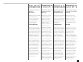
19
PROTECTION PROTECTION
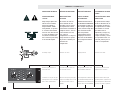
Turn-on/turn-off muting
The amplifier outputs are muted for
a couple of seconds after turn-on,
and immediately at turn-off.
Mise en sourdine lors de
la mise sous/hors tension.
Les sorties sont coupées pour
quelques secondes quand on allume
l’amplificateur, et immédiatement
quand on l’éteint.
Short circuit protection
The Output Averaging™ circuit
protects the output devices from
short circuits and stressful loads.
Stummschaltung bei
An-und Ausschalten
Der Verstärkerausgang ist nach dem
Einschalten für ein paar Sekunden
stummgeschaltet. Bei Ausschaltung
sofort.
Enmudecimiento de
encendido/apagado
Las salidas del amplificador se
enmudecen durante unas segundos
al encender y apagar.
Protection contre les
court-circuits
Le circuit Output Averaging™
protège les transistors de sortie
contre les court-circuits et les
charges difficiles.
Schutz bei Kurzschluß
Die „Output Averaging™”-Schaltung
schützt die Ausgangstransistoren
vor Kurzschluß und Fehllast.
Protección contra
corto-circuito
El circuito Output Averaging™
protege los dispositivos de salida
contra corto circuitos y cargas
inadecuadas.
Limiteur d'écrêtement
En utilisation normale, le limiteur
d'écrêtement n'affecte pas le signal
audio et il est en fait inaudible. Il
permet l'écrêtement des transitoires
et n'entre en action que lors
d'écrêtement prolongé. Dans ce ças,
le limiteur réduit peu à peu le niveau
du signal audio (jusqu'à 10 dB) de
façon à minimiser l'écrêtement.
Lorsque l'écrêtement cesse, le
limiteur se retire et cesse la
réduction de gain.
Clip limiting
During normal operation, the clip
limiter does not affect the audio
signal and is, in fact, inaudible. It will
allow brief clipping of peaks,
activating only when continuous,
hard limiting occurs. The clip limiter
will then gradually reduce the audio
signal (up to 10dB) to minimize
clipping. When clipping ends, the clip
limiter will deactivate and return
gain to normal.
Übersteuerungsbegrenzung
Während normalen Betriebes ist der
Clip-Limiter unhörbar. Er erlaubt
kurzes harmlosen Clippen und wird
erst dann aktiv, wenn hartes,
dauerndes Clippen erfolgt. Der
Limiter wird dann das Audiosignal so
allmählich reduzieren (bis zu 10 dB),
daß nur noch geringes Clippen
erfolgen kann. Hört das Clippen auf,
wird der Limiter abgeschaltet und
beendet damit die
Verstärkungsreduzierung.
Limitando clips
Durante el funcionamiento normal
del amplificador, el limitador anti-clip
no afecta a la señal de audio y, de
hecho, es inaudible. Permitirá breves
clips debidos a picos de señal y solo
se activará cuando se produzca un
clip continuo o prolongado. El
limitador reducirá entonces gradual
la señal de audio (hasta 10 dB) hasta
eliminar el clip. Cuando el clip
desaperece, el limitador se
desactivará, finalizando su reducción
de ganancia.
PROTECCIÓNSCHUTZSCHALTUNGEN

20
Thermal protection
A variable-speed fan provides
adequate cooling air flow. But if the
heatsink temperature climbs above
90° C, the outputs will mute until the
amplifier cools down.
Protection thermique
Un ventilateur à vitesse variable
fournit le courant d’air nécessaire au
refroidissement de l’amplificateur. Si
la température du radiateur devait
dépasser 90° C, les sorties seraient
coupées jusqu’à ce que
l’amplificateur ait suffisament
refroidi.
Thermische
Schutzschaltung
Ein drehzahlgregelter Lüfter sorgt
für kühlenden Luftstrom. Falls die
Kühlkörper dennoch über 90° C
erhitzt werden, werden die
Ausgänge bis zum Erreichen einer
sicheren Betriebstemperatur
stummgeschaltet.
Protección térmica
Un ventilador de velocidad variable
proporciona el flujo de aire
adecuado para le refrigeración. Si la
temperatura del radiador sube por
encima de los 90° centígrados, las
salidas se enmudecen hasta que el
amplificador se enfría.
Input/output
protection
The input circuits are isolated by
resistors. An ultrasonic network
decouples RF from the outputs and
helps keep the amplifier stable with
reactive loads.
Protection entrées/
sorties
Les circuits d’entrée sont isolés par
des résistances. Un circuit
ultrasonique découple les RF (Radio
Fréquences) des sorties et aide à
maintenir la stabilité de
l’amplificateur sous des charges
réactives.
Eingangs-/
Ausgangsschutz
Die Eingangsschaltungen sind mit
Widerständen isoliert. Ein
Ultraschallfilter entkoppelt
Hochfrequenz von den Ausgängen
und stabilisiert die
Ausgangsschaltkreise gegen
rückwirkende Störpegel oder
Störspannungen.
Protección entrada/
salida
Las entradas están aislidas a través
de resistencia. Una red ultrasónica
elimina la radiofrecuencia de las
salidas y ayuda al comportamiento
estable del amplificador con cargas
reactivas.
Protection contre une
anomalie CC
L'amplificateur sera éteint en
présence de courant continu ou de
signal subsonique excessif aux
sorties.
Schutz gegen
Gleichspannung
Beim Auftreten von Gleichspannung
oder übermäßigen, tieffrequenten
Signalen (Infraschall) an den
Ausgängen, schaltet sich das Gerät
selbständig ab.
Protección contra
corriente continua
El amplificador cortará si hay
corriente continua o demasiada
energía subsónica en las salidas.
DC fault protection
The amplifier will shut down if DC or
excessive subsonic energy appears
at the outputs.
La page charge ...
La page charge ...

23
WARRANTY
INFORMATION
INFORMATIONS DE
GARANTIE
GARANTIE-
BEDINGUNGEN
INFORMACIÓN DE
GARANTÍA
Disclaimer
QSC Audio Products, LLC is not liable
for any damage to speakers,
amplifiers, or any other equipment
that is caused by negligence or
improper installation and/or use of
the PowerLight amplifier.
Product Warranty
QSC guarantees the PowerLight to
be free from defective material and/
or workmanship for a period of three
years from the date of sale, and will
replace defective parts and repair
malfunctioning products under this
warranty when the defect occurs
under normal installation and use—
provided the unit is returned to our
factory via prepaid transportation
with a copy of the proof of purchase,
i.e., sales receipt. This warranty
provides that examination of the
returned product must indicate, in
our judgment, a manufacturing
defect. This warranty does not
extend to any product which has
been subjected to misuse, neglect,
accident, improper installation, or
where the date code has been
removed or defaced.
Décharge
QSC Audio products, LLC ne peut
être tenu responsable de tout
dommage à des haut-parleurs,
amplificateurs, ou tout autre
équipement qui pourrait être dû à de
la négligence ou mauvaise
installation et/ou utilisation d'un
amplificateur PowerLight.
Garantie de produit
QSC garantit le produit PowerLight
libre de défaut de pièce et/ou de
fabrication, et ce pour une période
de trois ans à partir de la date
d'achat, et remplacera les pièces
défectueuses et réparera le produit
sous l'effet de cette garantie en
autant que le produit est installé et
utilisé de façon normale, et que le
produit est retourné à notre usine
port payé, accompagné d'une copie
de la preuve d'achat, i.e. facture
originale. Cette garantie est
conditionnelle à ce qu'une inspection
du produit retourné révèle, selon
notre jugement, un défaut de
fabrication. Cette garantie ne couvre
pas les produits ayant subi abus,
négligence, accident, installation
incorrecte, ou dont le code de date a
été enlevé ou rendu illisible.
(USA only; see your dealer or
distributor)
(É-U seulement; consultez votre
marchand ou distributeur)
(Nur USA; in anderen Ländern
Ihren Fachhändler fragen.)
(EE. UU. solamente; consulte su
comerciante o su distribuidor)
Atención
QSC Audio Products, LLC no es
responsable por daños a las bocinas,
amplificadores o cualquier otro
equipo que sea causado por
negligencia o mala instalación o uso
de los amplificadores PowerLight.
Garantía
QSC garantiza que el PowerLight
estará libre de defectos en piezas o
mano de obra por un período de tres
años de la fecha de venta, y
cambiará las partes que no
funcionen y arreglará productos
cubiertos por esta garantía mientras
que el defecto surja bajo condiciones
normales de uso y asumiendo que la
unidad será enviada a nuestra
fábrica vía transporte prepagado con
una copia de la prueba de compra
(ejemplo: recibo de venta). Esta
garantía dependerá de una
examinación del producto devuelto y
deberá indicar, a nuestro juicio, un
defecto de fabrica. Esta garantía no
se extiende a ningún producto que
ha sido sometido a uso fuera de
nuestras recomendaciones,
accidentes, instalación deficiente y si
el código de la fecha ha sido
enmendado o retirado.
Haftungserklärung
QSC Audio Products, LLC haftet nicht
für Schäden an Lautsprechern,
Verstärkern, oder anderen Geräten,
die durch Fahrlässigkeit im Betrieb
oder durch nachlässige Installation
verursacht wurden.
Produktgarantie
QSC garantiert für die PowerLight-
Verstärker einwandfreie Herstellung
und Freiheit von Materialmängeln
für die Dauer von drei Jahren nach
Verkaufsdatum. Innerhalb dieser Zeit
ersetzt QSC defekte Teile und
repariert nicht funktionierende
Komponenten /Produkte, wenn der
Defekt unter normalen
Betriebsumständen auftritt. Dies bei
frachtfreiem Versand zum Hersteller,
mit Kaufquittung. Der Garantiefall
muss nach unserer Untersuchung
und nach unserem Urteil, durch
einen Herstellungsfehler ausgelöst
worden sein. Eine weitergehende
Haftung für Produkte, die
missbräuchlich genutzt wurden,
durch Fahrlässigkeit beschädigt
worden sind, durch Unfall, durch
unsachgemässe Installation, oder bei
Entfernung des Datumscodes,
schliessen wir aus.

24
ADDRESS
&
TELEPHONE
INFORMATION
ADRESSE
POSTALE
ET
NUMÉROS
DIRECCIÓN
Y
TELÉFONO
ANSCHRIFT
UND
TELEFON-
NUMMERN
Mailing address / Adresse postale / Postanschrift / Dirección postal: QSC Audio Products, LLC
1675 MacArthur Boulevard
Costa Mesa, CA 92626-1468 USA
Telephone Numbers / Numéros de téléphone / Telefonnummern / Números de teléfono:
Main Number / Numéro principal / Hauptnummer / Número principal +1 (714) 754-6175
Sales Direct Line / Ligne directe ventes / Verkauf-Direkt / Línea directo ventas +1 (714) 957-7100
Sales & Marketing / Ventes & marketing / Verkauf u. Marketing / Ventas y marketing (800) 854-4079
(toll-free in U.S.A. only)
(sans frais aux É-U seulement)
(zollfrei nur beim USA)
(sin costo en EE. UU. solamente)
Customer Service / Service à la clientèle / Kundendienst / Servicio a la clientela +1 (714) 957-7150
(800) 772-2834
(toll-free in U.S.A. only)
(sans frais aux É-U seulement)
(zollfrei nur beim USA)
(sin costo en EE. UU. solamente)
Facsimile Numbers / Numéros de télécopieur / Telefaxnummern / Número de FAX:
Sales & Marketing FAX / Télécopie ventes & marketing / Telefax der Verkauf u. Marketing / FAX ventas y marketing
+1 (714) 754-6174
Customer Service FAX / Télécopie service à la clientèle / Kundendienst-Telefax / FAX servicio a la clientela
+1 (714) 754-6173
World Wide Web: www.qscaudio.com (product informtaion)
www.qscstore.com (parts and accessories)
E-mail: [email protected]
La page charge ...
La page charge ...
-
 1
1
-
 2
2
-
 3
3
-
 4
4
-
 5
5
-
 6
6
-
 7
7
-
 8
8
-
 9
9
-
 10
10
-
 11
11
-
 12
12
-
 13
13
-
 14
14
-
 15
15
-
 16
16
-
 17
17
-
 18
18
-
 19
19
-
 20
20
-
 21
21
-
 22
22
-
 23
23
-
 24
24
-
 25
25
-
 26
26


QSC PL-3.4 Manuel utilisateur
- Catégorie
- Matériel musical
- Taper
- Manuel utilisateur
dans d''autres langues
- English: QSC PL-3.4 User manual
- español: QSC PL-3.4 Manual de usuario
- Deutsch: QSC PL-3.4 Benutzerhandbuch
Documents connexes
-
QSC PL-1.6HVX Manuel utilisateur
-
-
-
QSC POWERLIGHT PL340 Manuel utilisateur
-
-
-
QSC ISA300Ti Manuel utilisateur
-
QSC DCA 3422 Manuel utilisateur
-
QSC PL-4.0 Manuel utilisateur
-
QSC PL340 Manuel utilisateur