Sonance DSP 2-150 MKII Manuel utilisateur
- Catégorie
- Amplificateurs audio
- Taper
- Manuel utilisateur
Ce manuel convient également à

SR 2-125
TWO-CHANNEL AMPLIFIER
INSTRUCTION MANUAL
33-7575 10.11.18

SR 2-125 TWO-CHANNEL AMPLIFIER INSTRUCTION MANUAL
TABLE OF CONTENTS
Safety 1
Introduction/Box Contents 3
Front Panel/Rear Panel 4
Amplifier Power Requirement Chart 6
Connections and Volume Level Controls 7
Protection Circuitry and LEDs 8
Quick Setup Page 9
Specifications 10
Warranty 11

SR 2-125
TWO-CHANNEL AMPLIFIER
INSTRUCTION MANUAL
Important Safety Information
You should always follow these basic safety precautions when using
your SR 2-125 amplifier to reduce the risk of fire, electric shock, and
injury to persons:
1. Read and retain instructions: Read all the safety and
operating instructions before operating the amplifier, and
retain them for future reference.
2. Heed warnings: Adhere to all warnings and precautions listed
on the amplifier and in the operating instructions.
3. Follow instructions: Follow all operating instructions.
4. Water: Never use the amplifier next to water.
5. Carts and stands: The amplifier should
be used only with a cart or stand that is
recommended by the manufacturer. An
amplifier and cart combination should be
moved with care.
6. CAUTION: TO PREVENT ELECTRIC SHOCK, DO NOT USE
THE POLARIZED PLUG WITH AN EXTENSION CORD,
RECEPTACLE, OR OTHER OUTLETS UNLESS THE BLADES
CAN BE FULLY INSERTED TO PREVENT BLADE EXPOSURE.
7. Ventilation: Situate the amplifier so that its location does not
interfere with its proper ventilation.
8. Heat: Situate the amplifier away from heat sources such as
radiators, stoves, or other appliances (including amplifiers) that
produce heat.
9. Grounding or polarization: Grounding or polarization are
precautions that should be taken so that these attributes are
not defeated.
10. Power-cord protection: Route power supply cords so that
they will not be walked on or pinched by items placed on or
against them.
11. Cleaning: To clean the amplifier, use “canned air” or wipe the
amplifier with a soft cloth. Do not use solvents as they may
damage the amplifier.
12. Non-use periods: Unplug the amplifier’s power cord from the
outlet when the amplifier will be left unused for a long period
of time.
13. Object entry: Care should be taken so that objects do not fall
through the opening of the enclosure.
14. Moisture: Do not expose the amplifier to dripping or splashing.
Do not place objects filled with liquids, such as vases, on
the amplifier.
15. Damage requiring service: Have the amplifier serviced by a
qualified service personnel when:
• The power supply cord or the plug has been damaged.
• Objects have fallen, or liquid has been spilled into
the amplifier.
• The amplifier has been exposed to rain.
• The amplifier does not appear to operate normally or exhibits
a marked change in performance.
• The amplifier has been dropped, or the enclosure damaged.
16. Servicing: The user should not attempt to service the amplifier
beyond that described in the operating instructions. All other
servicing should be referred to qualified service personnel.
17. Lifting: Improper lifting of the 11 lbs. SR 2-125 amplifier can
cause personal injury.
18. Power requirement: Do not connect the SR 2-125 amplifier
to the accessory outlet of any other component. A minimum 15
amp (20 amp preferred) grounded wall outlet is required.
WARNING: THE POWER (MAINS) PLUG SERVES AS THE
AMPLIFIER’S DISCONNECT DEVICE. THE DISCONNECT DEVICE
SHALL REMAIN READILY OPERABLE DURING OPERATION.
TO ENSURE THAT THE DISCONNECT DEVICE (POWER PLUG)
IS EASILY ACCESSIBLE, THE USER SHALL NOT PLACE THE
AMPLIFIER IN A CONFINED AREA DURING OPERATION.
19. Storms: To prevent damage to components, unplug all
electronic equipment during thunderstorms.
1

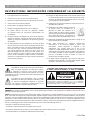
INSTRUCTIONS IMPORTANTES CONCERNANT LA SÉCURITÉ
1. Lisez soigneusement ces instructions.
2. Conservez-les en lieu sûr pour toute référence future.
3. Respectez scrupuleusement tous les avertissements de sécurité.
4. Suivez toutes les instructions indiquées.
5. Ne pas utiliser cet appareil près de l’eau.
6. Nettoyez cet appareil uniquement avec un chiffon sec.
7. Ne jamais obstruer ses ouïes de ventilation. Installez
cet appareil suivant les instructions recommandées par
son fabricant.
8. Ne jamais installer cet appareil près d’une source dechaleur,
comme les radiateurs, bouches de chaleur, fours ettout autre
appareil (y compris les amplificateurs de puissance) générant
de la chaleur.
9. Ne jamais démonter la prise polarisée ou la broche de mise
à la terre de la prise secteur. Une prise polarisée possède deux
lames, l’une étant plus large que l’autre (standard américain).
Une prise avec mise à la terre possède trois broches, dont
une centrale déportée par rapport aux deux autres. Ces
différents brochages ont été conçus pour votre sécurité. Si la
prise de l’appareil ne rentre pas dans la prise d’alimentation
secteur de votre installation, veuillez consulter un électricien
agréé pour le remplacement de la prise murale (certainement
pas aux normes actuelles).
Le symbole de l’éclair terminé par une pointe de flèche,
dans un triangle équilatéral, est utilisé pour indiquer
à l’utilisateur la présence d’une tension électrique
potentiellement dangereuse, à l’intérieur de l’appareil, d’un niveau
suffisamment élevé pour présenter des risques d’électrisation aux
personnes physiques.
Le symbole du point d’exclamation, dans un triangle
équilatéral, est utilisé pour indiquer à l’utilisateur, dans
les manuels accompagnant l’appareil, la présence
d’un point très important, concernant le fonctionnement ou la
maintenance de l’appareil, à respecter impérativement.
10. Protégez le câble d’alimentation secteur de telle manière qu’il
ne puisse pas être écrasé ou pincé, particulièrement au niveau
des prises, du passage dans des goulettes prévues à cet usage,
ou à l’endroit où il sort de l’appareil.
11. N’utilisez que les systèmes de fixation et accessoires prévus et
conseillés par le fabricant.
12. N’utilisez que des tables, supports, pieds, bras
de fixation prévus ou conseillés par le
fabricant, ou vendus avec l’appareil. Si un
support mobile est utilisé, toujours procéder
avec une grand précaution lors du déplacement
dece support afin d’éviter que l’appareil ne
tombe et puisse blesser physiquement une personne.
13. Débranchez complètement l’appareil pendant un orage ou une
longue période de non-utilisation.
14. Pour toute intervention sur l’appareil, adressez-vous
exclusivement à du personnel qualifié et agréé. Une
interventions’ avérera nécessaire si l’appareil a été
endommagé, pour quelque raison que ce soit, et par
exemple si le câble d’alimentation secteur ou sa prise sont
endommagés, si du liquide a pénétré à l’intérieur de l’appareil,
ou un objet y est tombé, ou bien si l’appareil a été exposé à la
pluie ou à l’humidité, ou bien est tombé, ou encore ne
fonctionne pas de manière normale.
15. Ne jamais exposer cet appareil à des risques de coulures ou
d’éclaboussures de liquides ; ne jamais poser d’objets remplis
de liquide – comme des vases, sur l’appareil.
ATTENTION
RISQUED’ÉLECTRISATION
NEPASOUVRIR
ATTENTION
:
AFINDERÉDUIRELESRISQUESD’ÉLECTRISATION, NE
JAMAISÔTERLECAPOTDEL’APPAREIL.ILN’YAÀL’INTÉRIEUR
AUCUNE PIÈCESUSCEPTIBLED’ÊTREMODIFIÉEPARL’UTILISATEUR.
TOUJOURS FAIREAPPELÀUNTECHNICIENAGRÉÉ.
ATTENTION:POURRÉDUIRETOUTRISQUED’ÉLECTROCUTION,
NEJAMAISEXPOSERCET APPAREILÀLAPLUIEOUL’HUMIDITÉ.
ATTENTION
RISQUED’ÉLECTRISATION
NEPASOUVRIR
ATTENTION
:
AFINDERÉDUIRELESRISQUESD’ÉLECTRISATION, NE
JAMAISÔTERLECAPOTDEL’APPAREIL.ILN’YAÀL’INTÉRIEUR
AUCUNE PIÈCESUSCEPTIBLED’ÊTREMODIFIÉEPARL’UTILISATEUR.
TOUJOURS FAIREAPPELÀUNTECHNICIENAGRÉÉ.
ATTENTION:POURRÉDUIRETOUTRISQUED’ÉLECTROCUTION,
NEJAMAISEXPOSERCET APPAREILÀLAPLUIEOUL’HUMIDITÉ.
WARNING: Any changes or modifications to this unit not expressly approved by the party responsible for compliance could void the user’s
authority to operate the equipment.
NOTE: This equipment has been tested and found to comply with the limits for a Class B digital device, pursuant to part 15 of the FCC
Rules. These limits are designed to provide reasonable protection against harmful interference in a residential installation. This equipment
generates, uses and can radiate radio frequency energy and, if not installed and used in accordance with the instructions, may cause harmful
interference to radio communications. However, there is no guarantee that interference will not occur in a particular installation. If this
equipment does cause harmful interference to radio or television reception, which can be determined by turning the equipment off and on,
the user is encouraged to try to correct the interference by one or more of the following measures:
• Reorient or relocate the receiving antenna.
• Increase the separation between the equipment and receiver.
• Connect the equipment into an outlet on a circuit different from that to which the receiver is connected.
• Consult the dealer or an experienced radio/TV technician for help.
SR 2-125 TWO-CHANNEL AMPLIFIER INSTRUCTION MANUAL
2

Introduction
Thank you for purchasing the SONANCE SR 2-125 amplifier.
When properly installed, this amplifier will give you many years of
entertainment pleasure. To get the most out of your new amplifier
please read this manual thoroughly before you begin installation.
To achieve the best performance SONANCE recommends that this
amplifier be installed by a SONANCE Authorized Dealer/Installer.
Placement
Place the amplifier on a level surface, in an upright position, out
of direct sunlight and away from windows through which rain
may enter.
Situate the amplifier away from heat sources such as hot air ducts
or radiators. Be sure that the amplifier is adequately ventilated by
convection or suitable cabinet fans.
• Never place any object on or against the amplifier.
• Never operate the amplifier on a carpeted surface as this will
compromise ventilation.
• When the amplifier is installed in any cabinet, the front or back
must be open during operation. Alternately, install fans in the
cabinet to assure continuous ventilation.
Box Contents
Your SR 2-125 amplifier box should contain:
(1) Instruction manual
(1) SR 2-125 amplifier
(1) IEC power cord
(4) Feet
(2) Long rack ears
(1) DSP Preset matrix
Unpacking
Save the carton and polystyrene inserts for future safe transport in
case the amplifier is moved or requires shipping for repair.
Before proceeding with installation locate the serial number on the
rear panel of the unit and note it here for future reference:
S/N:_________________________________________________________
3
SR 2-125 TWO-CHANNEL AMPLIFIER INSTRUCTION MANUAL
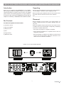
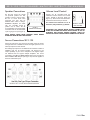
FIGURE 1: SR 2-125 TWO-CHANNEL AMPLIFIER

4
SR 2-125 TWO-CHANNEL AMPLIFIER INSTRUCTION MANUAL
FIGURE 3: SR 2-125 TWO-CHANNEL AMPLIFIER REAR PANEL
FIGURE 2: SR 2-125 TWO-CHANNEL AMPLIFIER FRONT PANEL
SR 2-125 Front Panel
1. Illuminated Power Button
2. Power, Active & Protection Indicator LED
3. Recessed Volume Level Control
SR 2-125 Rear Panel
4. L/R Line In/Coax/Toslink
5. Speaker Block Connector
6. Audio Auto On/Off Switch
7. EQ Preset Bank
8. EQ Preset Selection
9. AC Fuse Holder
10. Power Cord Connection
1 2 3
5 8
10
7
6 94

5
SR 2-125 TWO-CHANNEL AMPLIFIER INSTRUCTION MANUAL
Front Panel
Power Switch
The power switch turns the amplifier on and off.
When the power switch is lit solid white, the amplifier has power, is
turned ON and ready to operate.
When the power switch is slightly dimmed the amplifier is in
standby mode.
When the power switch is blinking white, the amplifier power supply
is in thermal protection. The channel LEDs will also light red when
the power supply is in thermal protect mode.
NOTE: Upon initial power up there will be an approximately 9-12
second boot up cycle. This is normal.
Input/Output Lights
When each channel is active, the LED will light green as long as a
signal is present.
When the LED blinks red, this is an indication that the channel is
being overdriven.
When the LED lights are solid red this is an indication the amplifier
is in protect mode. While in protect mode the LED lights will
periodically light green to retest the output to determine if the short
has been removed. Protect mode could be caused by a short in the
wire, overheating of the amplifier or possibly an internal problem
with the amplifier.
NOTE: WHEN ANY OF THE LEDS ARE LIT RED TURN THE
AMPLIFIER OFF IMMEDIATELY. DETERMINE THE CAUSE OF THE
PROBLEM BEFORE TURNING THE AMPLIFIER ON.
Volume Level Control
Each channel on the amplifier has front panel recessed volume
controls that will adjust the output and turn on volume. The amplifier
must be powered on to make these adjustments.
Rear Panel
Inputs
The SR 2-125 amplifier has analog, coax and toslink LINE INPUTS
and loop OUTPUTS.
The analog loop outputs are non buffered. The maximum number
of amplifiers that can be looped together will depend on the output
capability of your source component. The digital outputs are
buffered and can support multiple amplifiers. Only one output can
be used at a time.
Speaker Connections
The removable block connectors used on the SR 2-125 amplifiers
will accept up to 12 gauge wire.
Follow the connection layout on the rear panel of the amplifier.
Make sure no bare wires come in contact with the amplifier chassis.
AC Fuse Holder
To replace the fuse, unplug the power cord from the Power Cord
Connector and use a screwdriver to remove the fuse holder.
SR 2-125 - 5 amp AC (T5-AL)
CAUTION: FOR CONTINUED PROTECTION AGAINST FIRE,
REPLACE THE FUSE WITH ONLY THE SAME TYPE AND RATING.
Power Cord
The SR 2-125 amplifiers feature removable IEC power connectors.
Plug the female end of the power cord into the Power Cord
Connector on the amplifier rear panel and plug the male end into a
grounded wall socket.
DO NOT plug the amplifier’s power cord into a convenience outlet
on any other audio or video component. If you need to use an
extension cord, use only a heavy duty (14-GAUGE OR LARGER)
extension cord to avoid starving the amplifier of the current
necessary for full operation.
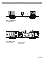
FIGURE 4: SR 2-125 AMPLIFIER FRONT PANEL VIEW FIGURE 5: SR 2-125 AMPLIFIER REAR PANEL VIEW

6
SR 2-125 TWO-CHANNEL AMPLIFIER INSTRUCTION MANUAL
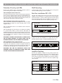
Powering the Amplifier
The SR 2-125 features a removable
IEC power connector (Figure 6).
A 14-gauge EIA standard 120-volt
grounded power cable is included with
the amplifier.
Each time the amplifier’s power
cord is initially plugged in and the
POWER switch is turned ON, all
channel outputs are disconnected
for approximately 9-12 seconds and all
PROTECTION LEDs will illuminate briefly
while the amp boots up.
IMPORTANT: DO NOT PLUG THE POWER CORD INTO THE WALL
OUTLET UNTIL ALL SYSTEM CONNECTIONS HAVE BEEN MADE
AND VERIFIED.
Plug the female end of the power cable into the Power Connector
on the amplifier’s rear panel and plug the male end directly into a
grounded 15 amp or 20 amp wall outlet.
IMPORTANT: DO NOT PLUG THE AMPLIFIER’S POWER CORD
INTO A CONVENIENCE OUTLET ON ANY OTHER AUDIO OR
VIDEO COMPONENT.
If the electrical service is subject to frequent sags, spikes, or
brownouts, a power conditioner designed for use with high fidelity
equipment should be employed to protect the amplifier.
CAUTION: FOR CONTINUED PROTECTION AGAINST FIRE,
REPLACE THE FUSE WITH ONLY THE SAME TYPE AND RATING.
Source Connections/Selection SR 2-125
There are two options when connecting audio inputs to the
SR 2-125 amplifier (see Figure 8):
Primary Line Inputs 1-L, 1-R - Use these inputs for analog
audio source.
Primary Line Coax Inputs L&R - Use these inputs for
coax audio source.
Primary Line Toslink Inputs L&R - Use these inputs for
toslink audio source.
Amplifiers Power Requirements: 15 AMP Breaker 20 AMP Breaker
Model Input Voltage Output Power (sinewave) Draw Watts Qty of Amplifiers Qty of Amplifiers
SR 2-125 100-120V AC Full Power All Channels @ 8 ohms 311.5 4 6
Full Power All Channels @ 4 ohms 326 4 5
1/8 Power All Channels @ 8 ohms 61.5 23 31
1/8 Power All Channels @ 4 ohms 63 22 30
@ Idle 26.5
@ Standby 0.3
13 AMP Breaker 20 AMP Breaker
Model Input Voltage Output Power (sinewave) Draw Watts Qty of Amplifiers Qty of Amplifiers
SR 2-125 220-240V AC Full Power All Channels @ 8 ohms 300 4 6
Full Power All Channels @ 4 ohms 314.5 4 6
1/8 Power All Channels @ 8 ohms 58.5 24 32
1/8 Power All Channels @ 4 ohms 60 24 32
@ Idle 24
@ Standby 0.48
FIGURE 8: SR 2-125 LEFT, RIGHT LINE INPUTS
FIGURE 7: SR 2-125 TWO-CHANNEL AMPLIFIER POWER REQUIREMENTS
IN
O
UT
1-L 1-R
LEVEL LEVEL
B
RIDGE
OFF ON
C
AUTION
RISK OF ELECTRIC SHOCK
D
O NOT OPEN
AVIS
RISQUE DE CHOC ELECTRIQUE
NE P
AS OUVRIR
S/N
T5AL / 250VAC
2-100
AC 100-120V ~ 60Hz
CAUTION
R
EPLACE FUSE ONLY WITH
S
AME TYPE AND RATING
ATTENTION
R
EMPLACER UNIQUEMENT AVEC LE
MEME TYP
E ET CALIBRE DU FUSIBLE
VOLTAGE TRIGGER
IN OUT
AUTO ON
OFF
1 - LEFT
1 - R
IGHT
BRIDGE
CLASS 2 WIRING
VOLTAGE
AUDIO
3-30 VOLTS
AC or DC
8 Ω MIN
AC 220-240V ~ 50Hz
52 watts
FIGURE 6: IEC POWER
CORD CONNECTION

7
SR 2-125 TWO-CHANNEL AMPLIFIER INSTRUCTION MANUAL
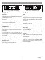
Speaker Connections
FIGURE 11: VOLUME
LEVEL CONTROL
FIGURE 9:
SPEAKER CONNECTORS
Volume Level Control
Volume can be controlled from the
individual recessed volume level control
screws, located on the front panel (see
Figure 11). These volume controls balance
the desired sound levels per channel.
The volume level controls are set to
maximum, fully clockwise, by default.
For the best sound you should
use premium speaker wire that
complies with fire rating codes.
Be sure to check local codes
governing wire that may be
installed within walls or ceilings.
SONANCE amplifiers are stable
with any reputable brand of
speaker wire or cable. The SR
2-125 amplifiers use speaker block
connectors that can accommodate
up to 12 gauge wire (see Figure 9).
NOTE: ALWAYS CHECK LOCAL BUILDING CODES BEFORE
INSTALLING WIRE IN WALLS OR CEILINGS.
IMPORTANT: USE CAUTION WHEN SETTING VOLUME LEVELS
EITHER ON THE AMPLIFIER OR AN AUDIO SOURCE AS NOT TO
OVERDRIVE AND POSSIBLY DAMAGE SPEAKERS. VERIFY ALL
SOURCES AS OUTPUT VOLTAGE VARIES FROM DEVICE TO DEVICE.
Source Connections SR 2-125
On the left side of the rear panel are the audio inputs for the left
and right channels. In addition to the left and right inputs there are
also loop outputs for each channel.
The analog loop outputs are non buffered. The maximum number of
amplifiers that can be looped together will depend on the
output capability of your source component. The digital outputs
are buffered and can support multiple amplifiers. The source
connected to the LEFT and RIGHT LINE IN Inputs pass through the
LEFT and RIGHT LINE Outputs (see Figure 10). This also applies to
the Coax and Toslink inputs.
FIGURE 10: SR 2-125 LEFT, RIGHT LINE INPUTS/OUTPUTS

8
SR 2-125 TWO-CHANNEL AMPLIFIER INSTRUCTION MANUAL
Protection Circuitry and LEDs
The SR 2-125 amplifiers have a multi-stage protection system to
prevent damage to your amplifier and speakers.
SR 2-125 Amplifier Channel Protection
If a channel encounters a short-circuit or an extremely low impedance
this will cause the affected channel outputs to automatically mute.
The output of the affected channel will remain muted until the fault
has been corrected. Only the affected channels output will mute, all
other channels will continue to operate normally.
SR 2-125 Amplifier Channel Protection Indication
On the front panel of the SR 2-125 amplifiers are dual color LEDs
that illuminate to indicate the current operating status of each
amplifier channel.
When the LED blinks red this is an indication that the channel is
being overdriven.
When the LED lights are solid red this is an indication the amplifier
is in protect mode. While in protect mode the LED lights will
periodically light green to retest the output to determine if the short
has been removed. Protect mode could be caused by a short in the
wire, overheating of the amplifier or possibly an internal problem
with the amplifier.
IMPORTANT: ALLOWING THE AMPLIFIER TO OPERATE WITH
ONE OR MORE CHANNELS IN PROTECT MODE FOR AN
EXTENDED PERIOD OF TIME CAN DAMAGE THE AMPLIFIER.
SR 2-125 Amplifier Power Supply Protection
The amplifier also has protection for the power supply. If the power
supply heat sink temperature exceeds the design maximum the
protection circuit will activate disconnecting all channel outputs. This
is indicated by a blinking light on the front panel power switch.
IMPORTANT: ANY TIME THE PROTECTION CIRCUITS ARE
TRIGGERED, UNPLUG THE AMPLIFIER’S POWER CORD FROM
THE WALL OUTLET BEFORE TROUBLESHOOTING.
Rack Ear Installation SR 2-125
The SR 2-125 amplifier ships with two long rack ears for when the
amplifier is to be used alone in a 1U space. Unscrew the four Phillips
head screws (M4 x 0.7 pitch x 10mm long) found on each side of
the left and right forward section of amplifier. Use these screws to
connect the included rack ears to the amplifier (see Figure 12).
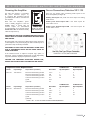
FIGURE 12: RACK EAR INSTALLATION SR 2-125
SIDE VIEW RIGHT
FRONT VIEW
Amplifier Stacking
The SR 2-125 amplifier is capable of being directly stacked with
the feet removed (see Figure 14) for use in low to moderate output
applications. For high-output applications, it is recommended to
leave at least 1U space between amplifiers for increased ventilation.
It is not recommended to stack more than three amplifiers high
without spacing.
Shelf Mounting
If shelf mounting, attach the four included feet by screwing them
into the threaded openings, no tool is required.
To place two SR 2-125 amplifiers in a single rack unit order:
Rack Mount Bracket for SR 2-125 SKU# 93098 (see Figure 13).
FIGURE 14: STACKED CONFIGURATION (3) SR 2-125
FIGURE 13: RACK MOUNT BRACKET FOR (2) SR 2-125
FRONT VIEW
FRONT VIEW

9
SR 2-125 TWO-CHANNEL AMPLIFIER INSTRUCTION MANUAL
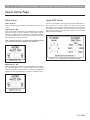
Quick Setup
Audio - Auto On
Select the Audio Auto On mode you would like to use, either ON
or OFF.
Audio Auto On - ON
When the Audio Auto On switch is in the ON position the amplifier
will power off after 15 minutes without an audio signal present on
any of the channels. When an audio signal is applied the amplifier
will take approximately 9-12 seconds to reproduce audio after
going through its power up sequence.
NOTE: THE AUDIO AUTO ON - ON MODE USES THE LEAST AMOUNT
OF AC POWER WHEN THE AMPLIFIER IS NOT OPERATING.
Audio Auto On - OFF
When the Audio Auto On switch is in the OFF position the amplifier
will enter Sleep Mode after 15 minutes without an audio signal
present on any of the channels. When an audio signal is applied the
amplifier will take approximately 2-3 seconds to reproduce audio.
Apply DSP Preset
The SR 2-125 amplifier includes pre-programmed DSP presets.
These presets are selected utilizing first the EQ Preset Bank
dial, followed by the EQ Preset Selection dial (see included DSP
Preset Matrix). The first EQ in any bank will be Flat. To select the
appropriate preset for your environment please see the included
DSP preset Selection Matrix.
Quick Setup Page
FIGURE 17: SR 2-125 EQ PRESET BANK & EQ PRESET SELECTION
FIGURE 16: SR 2-125
AUDIO AUTO ON - OFF
FIGURE 15: SR 2-125
AUDIO AUTO ON - ON

SPECIFICATIONS
SR 2-125 Amplifier
Number of Channels 2 (1 stereo pair)
Power Output - 8 ohms 125 Watts RMS per channel (both channels driven)
Power Output - 4 ohms 200 Watts RMS per channel (both channels driven)
Frequency Response 5Hz - 50kHz, bandwidth limited
Total Harmonic Distortion 0.07% (1kHz, 8 ohms) 0.06% (1kHz, 4 ohms)
Signal to Noise Ratio -100dB (20Hz-20kHz)
Input Gain 29dB
Input Sensitivity 100mV for 1 Watt Output @ 8 ohms
1110mV for 125 Watts Output @ 8 ohms
Input Impedance 20k ohms
Loop Output Impedance 600 ohms
Maximum Analog Input Voltage 2.9V VAC RMS
Power Consumption 120V AC
@8 ohms (sinewave, full power) 311.5 Watts (all channels driven)
@4 ohms (sinewave, full power) 326 Watts (all channels driven)
@8 ohms (sinewave, 1/8 power) 61.5 Watts (all channels driven)
@4 ohms (sinewave, 1/8 power) 63 Watts (all channels driven)
@idle 26.5 Watts
@standby 0.3 Watts
Power Consumption 220V AC
@8 ohms (sinewave, full power) 300 Watts (all channels driven)
@4 ohms (sinewave, full power) 314.5 Watts (all channels driven)
@8 ohms (sinewave, 1/8 power) 58.5 Watts (all channels driven)
@4 ohms (sinewave, 1/8 power) 60 Watts (all channels driven)
@idle 24 Watts
@standby 0.48 Watts
Heat Output
@8 ohms (sinewave, full power) 242 BTU (all channels driven)
@4 ohms (sinewave, full power) 314 BTU (all channels driven)
@8 ohms (sinewave, 1/8 power) 118 BTU (all channels driven)
@4 ohms (sinewave, 1/8 power) 124 BTU (all channels driven)
Operating Voltage 100-120V@60Hz, 220-240V@50Hz
AC Fuse 5A (T5AL ~ 250V)
Rack Space Requirement 1U – 1/2 Rack Width
Dimensions w/ Feet (W x H x D) 8 5/8” x 2 1/8” x 16 13/16” (219mm x 54mm x 427mm)
Dimensions w/ Rack Ears w/o Feet (W x H x D) 19” x 1 3/4” x 16 13/16” (482mm x 44mm x 427mm)
Shipping Weight 11 lbs (5.0kg)
CAD Files available for download at www.sonance.com
10
SR 2-125 TWO-CHANNEL AMPLIFIER INSTRUCTION MANUAL

©2018 Sonance. All rights reserved.
Sonance is a registered trademarks of Dana Innovations.
Due to continuous product improvement, all features and specifications are subject to change without notice.
For the latest Sonance product specification information visit our website: www.sonance.com
SONANCE • 991 Calle Amanecer • San Clemente, CA 92673 USA
(949) 492-7777 • FAX: (949) 361-5151 • Technical Support: (949) 492-7777
www.sonance.com
LIMITED TWO (2) YEAR WARRANTY
SONANCE warrants to the first end-user purchaser that this SR 2-125 Amplifier, when purchased from an authorized SONANCE Dealer/
Distributor, will be free from defective workmanship and materials for the period stated below. SONANCE will at its option and expense during
the warranty period, either repair the defect or replace the Product with a new or remanufactured Product or a reasonable equivalent.
EXCLUSIONS
TO THE EXTENT PERMITTED BY LAW, THE WARRANTY SET FORTH ABOVE IS IN LIEU OF, AND EXCLUSIVE OF, ALL
OTHER WARRANTIES, EXPRESS OR IMPLIED, AND IS THE SOLE AND EXCLUSIVE WARRANTY PROVIDED BY SONANCE.
ALL OTHER EXPRESS AND IMPLIED WARRANTIES, INCLUDING THE IMPLIED WARRANTIES OF MERCHANTABILITY,
IMPLIED WARRANTY OF FITNESS FOR USE, AND IMPLIED WARRANTY OF FITNESS FOR A PARTICULAR PURPOSE ARE
SPECIFICALLY EXCLUDED.
No one is authorized to make or modify any warranties on behalf of SONANCE. The warranty stated above is the sole and exclusive remedy
and SONANCE’S performance shall constitute full and final satisfaction of all obligations, liabilities and claims with respect to the Product.
IN ANY EVENT, SONANCE SHALL NOT BE LIABLE FOR CONSEQUENTIAL, INCIDENTAL, ECONOMIC, PROPERTY,
BODILY INJURY, OR PERSONAL INJURY DAMAGES ARISING FROM THE PRODUCT, ANY BREACH OF THIS WARRANTY
OR OTHERWISE.
This warranty statement gives you specific legal rights, and you may have other rights which vary from state to state. Some states do not allow
the exclusion of implied warranties or limitations of remedies, so the above exclusions and limitations may not apply. If your state does not
allow disclaimer of implied warranties, the duration of such implied warranties is limited to period of SONANCE’S express warranty.
Your Product Model and Description: SR 2-125 Two-Channel Amplifier
Warranty Period for this Product: Two (2) years from the date on the original sales receipt or invoice or other satisfactory proof of purchase.
Additional Limitations and Exclusions from Warranty Coverage: The warranty described above is non-transferable, applies only to the initial
installation of the Product, does not include installation of any repaired or replaced Product, does not include damage to allied or associated
equipment which may result for any reason from use with this Product, and does not include labor or parts caused by accident, disaster,
negligence, improper installation, misuse (e.g. overdriving the amplifier or speaker, excessive heat, cold or humidity), or from service or
repair which has not been authorized by SONANCE. Obtaining Authorized Service: To qualify for the warranty, you must contact your
authorized SONANCE Dealer/Installer or call SONANCE Customer Service at (949) 492-7777 within the warranty period, must obtain a
return merchandise number (RMA), and must deliver the Product to SONANCE shipping prepaid during the warranty period, together with
the original sales receipt, or invoice or other satisfactory proof of purchase.
SR 2-125 TWO-CHANNEL AMPLIFIER INSTRUCTION MANUAL
11
10.11.18
-
 1
1
-
 2
2
-
 3
3
-
 4
4
-
 5
5
-
 6
6
-
 7
7
-
 8
8
-
 9
9
-
 10
10
-
 11
11
-
 12
12
-
 13
13


Sonance DSP 2-150 MKII Manuel utilisateur
- Catégorie
- Amplificateurs audio
- Taper
- Manuel utilisateur
- Ce manuel convient également à
dans d''autres langues
- English: Sonance DSP 2-150 MKII User manual
Documents connexes
Autres documents
-
Yamaha P2050 Le manuel du propriétaire
-
-
-
Crown COMTECH DRIVECORE CT 4150 Le manuel du propriétaire
-
QSC PL-4.0 Manuel utilisateur
-
-
 YORKVILLE CR5 Le manuel du propriétaire
-
-
DYNACORD DPA 4260 Manuel utilisateur
